Removal Procedure
- With the tires in the straight forward position, remove the key from the ignition.
- Disconnect the negative battery cable. Refer to
Battery Negative Cable Disconnection and Connection
.
- Remove the air inlet duct and resonator . Refer to
Air Cleaner Outlet Resonator Replacement
.
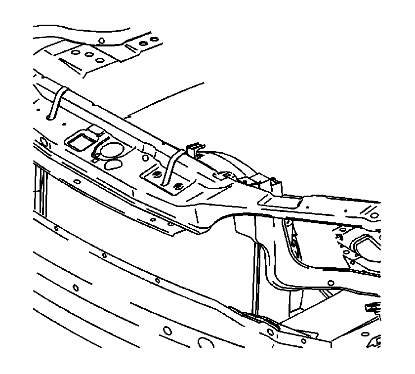
- Secure the cooling module to the upper body structure.
- Relieve the fuel system pressure. Refer to
Fuel Pressure Relief
.
- Disconnect the fuel line from the fuel rail. Refer to
Metal Collar Quick Connect Fitting Service
.
- Drain the cooling system. Refer to
Cooling System Draining and Filling
.
- Remove the radiator inlet hose. Refer to
Radiator Inlet Hose Replacement
.
- Remove the surge tank to cylinder head hose. Refer to
Radiator Surge Tank Inlet Hose/Pipe Replacement
and
Radiator Surge Tank Outlet Hose/Pipe Replacement
.
- Remove the radiator outlet hose. Refer to
Radiator Outlet Hose Replacement
.
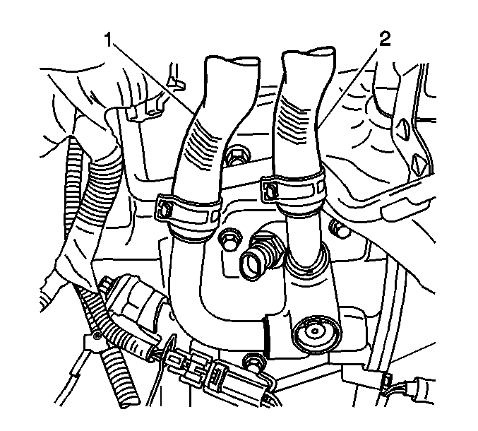
- Remove the inlet (1) and outlet (2) heater hoses. Refer to
Heater Inlet Hose Replacement
and
Heater Outlet Hose Replacement
.
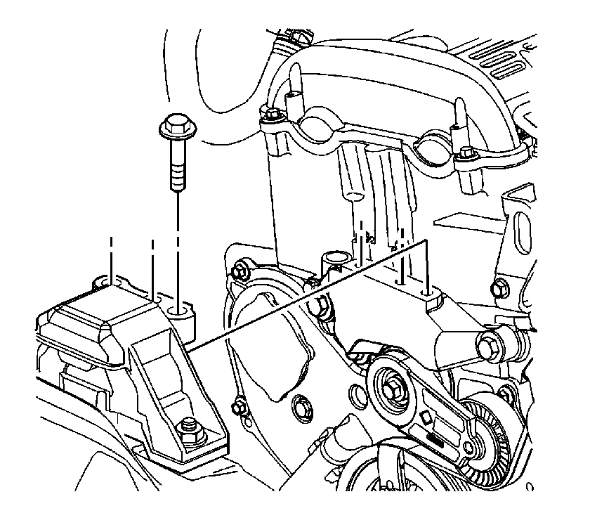
- Disconnect the following harness connectors:
| • | Idle air control (IAC) motor |
| • | Temperature position sensor (TPS) |
| • | Manifold absolute pressure (MAP) sensor |
| • | Ignition coil and module assembly |
| • | Engine temperature sensor |
- Raise and suitably support the vehicle. Refer to
Lifting and Jacking the Vehicle
.
- Remove the engine drive belt. Refer to
Drive Belt Replacement
.
- Remove the A/C compressor bolts and set the compressor aside.
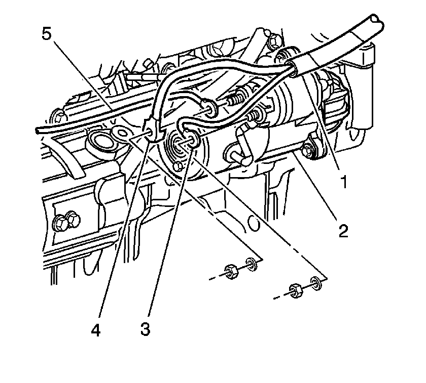
- Disconnect the starter harness connectors (3, 4, 5).
- Disconnect the generator harness connectors.
- Drain the engine oil.
- Disconnect the front exhaust pipe from the exhaust manifold. Refer to
Exhaust Manifold Replacement
.
- Disconnect the transmission harness connectors.
- Disconnect the transmission shift cable from the transmission.
- Use blocks of wood to support the powertrain assembly between the frame and the powertrain.
- Remove the engine mount. Refer to
Engine Mount Replacement
.
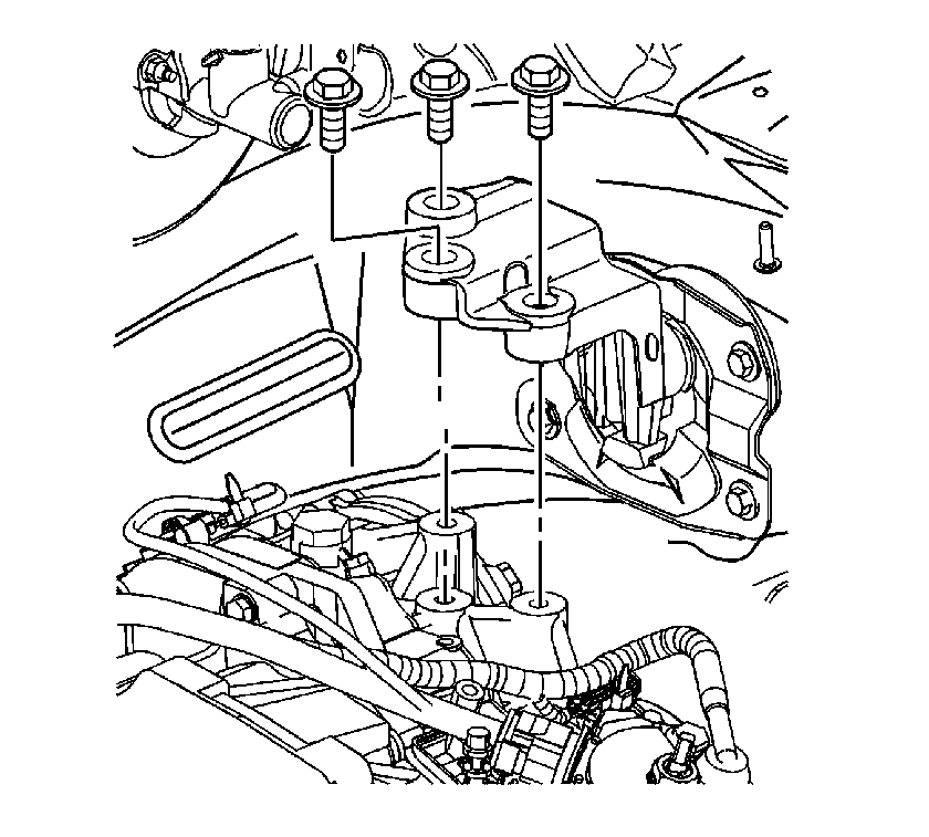
- Remove the side transmission mount. Refer to the appropriate procedure:
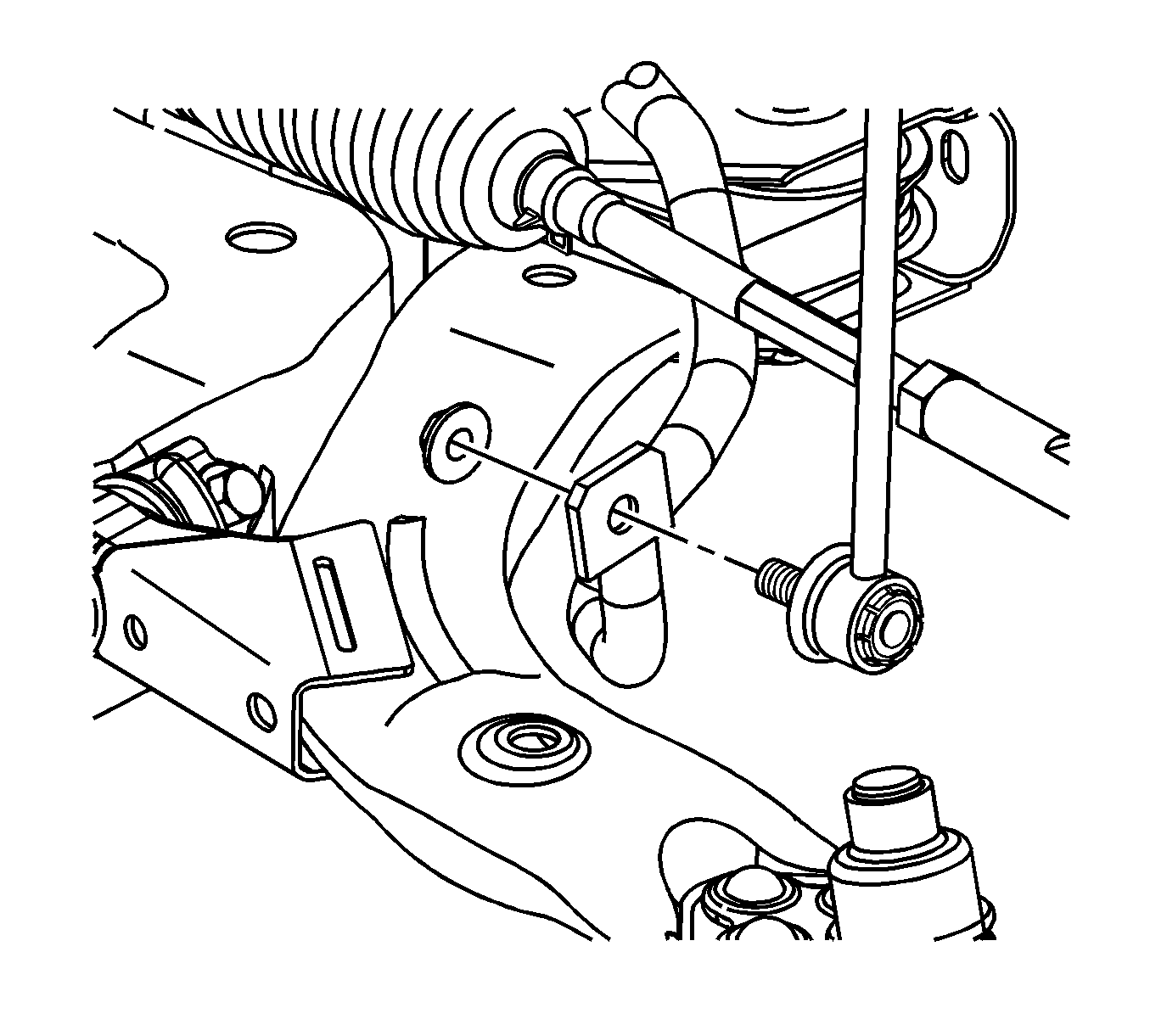
- Disconnect the stabilizer links from the stabilizer bar. Refer to
Stabilizer Shaft Link Replacement
.
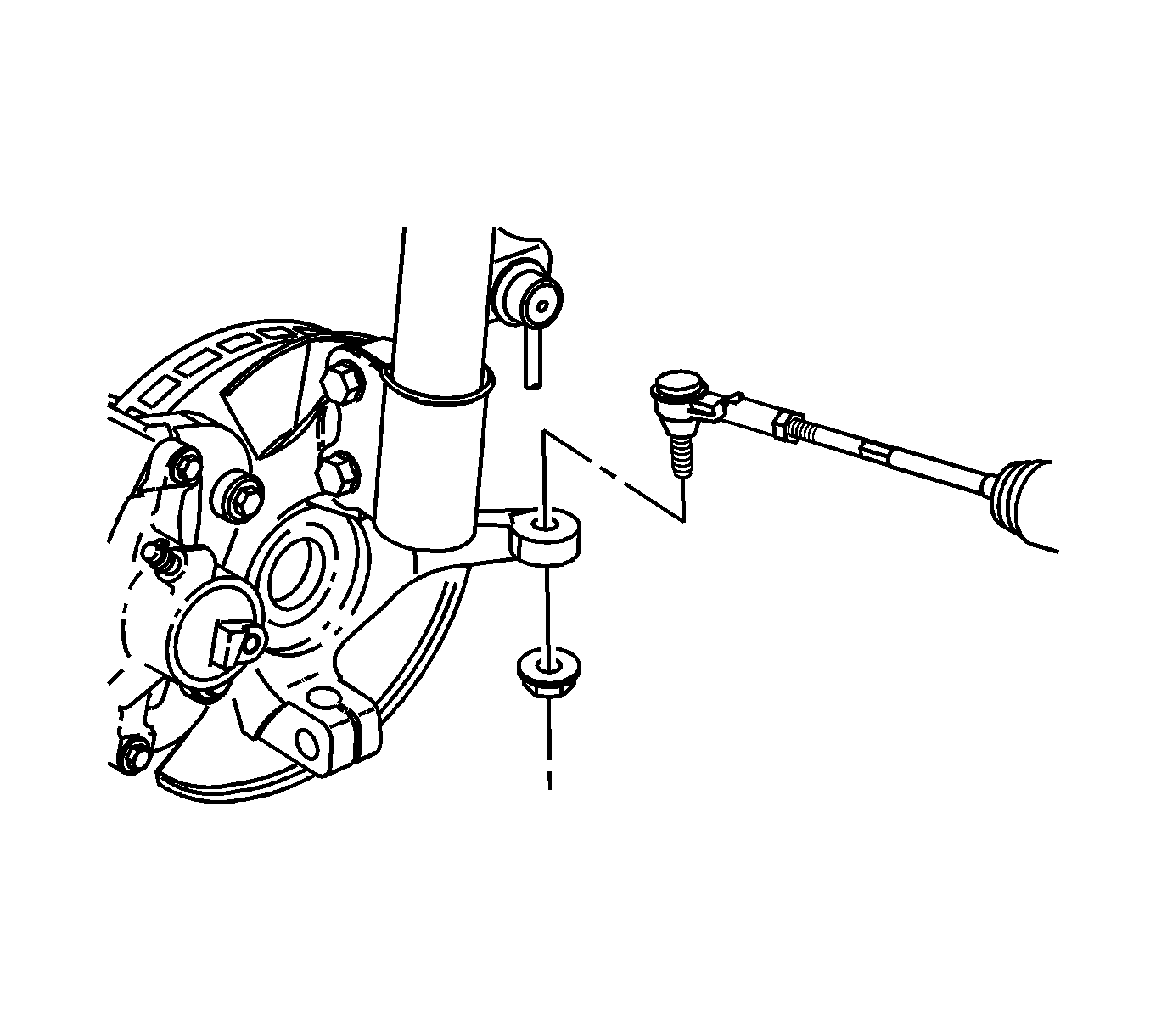
- Disconnect the outer tie rod ends from the steering knuckles. Refer to
Rack and Pinion Outer Tie Rod End Replacement
.
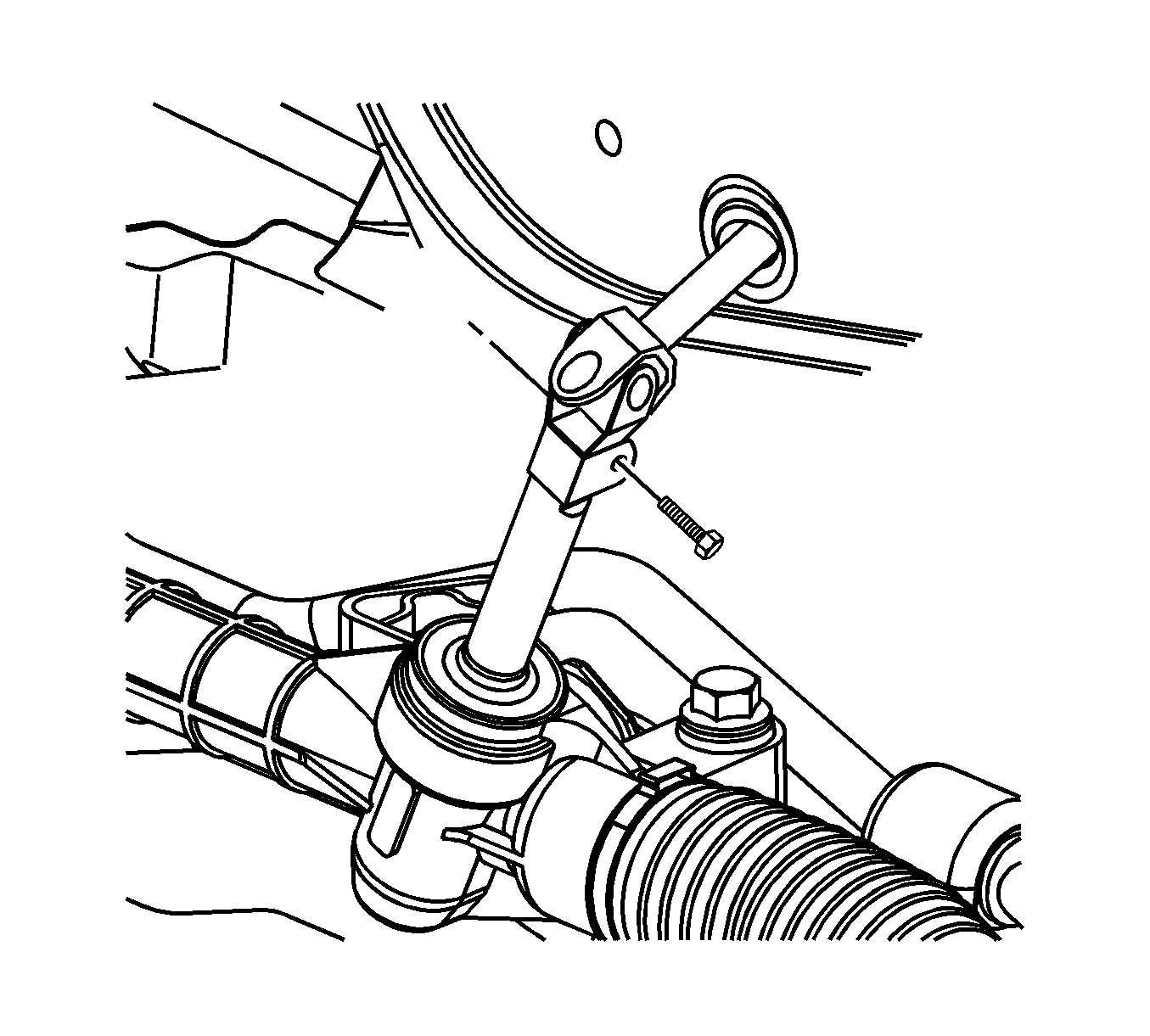
Important: In order to prevent possible SIR system deployment, do not attempt to rotate the steering shaft.
- Disconnect the intermediate shaft from the steering gear. Refer to
Intermediate Steering Shaft Replacement
.
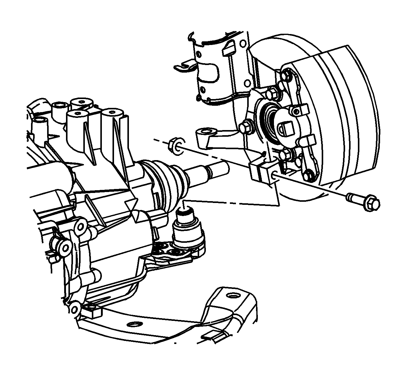
- Disconnect the lower control arms from the steering knuckles. Refer to
Lower Control Arm Replacement
.
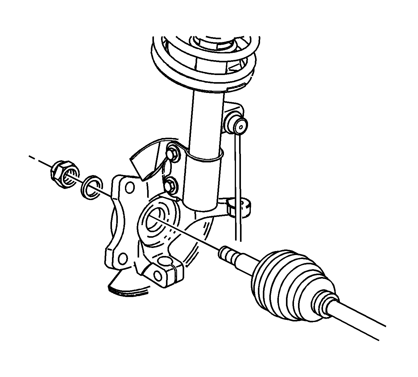
- Disconnect the drive axles from the steering knuckle. Refer to
Wheel Drive Shaft Replacement
.
- Use a paint pen or magic marker in order to mark the frame to body position.
- Lower the vehicle to about 1 m (3 ft) off the ground in order to position the lift table under the frame.
- Use wood blocks as necessary between the lift table and the frame to support the assembly.
- Slowly remove the frame bolts using the following sequence:
| 33.1. | Remove the front frame bolts. |
| 33.2. | Partially unscrew the rear frame bolts until 4 cm (1.5 in) of bolt shank is exposed. |
- Slowly lower the table to the floor with the cradle and powertrain assembly.
- Attach the engine lift hoist to the engine lift hooks.
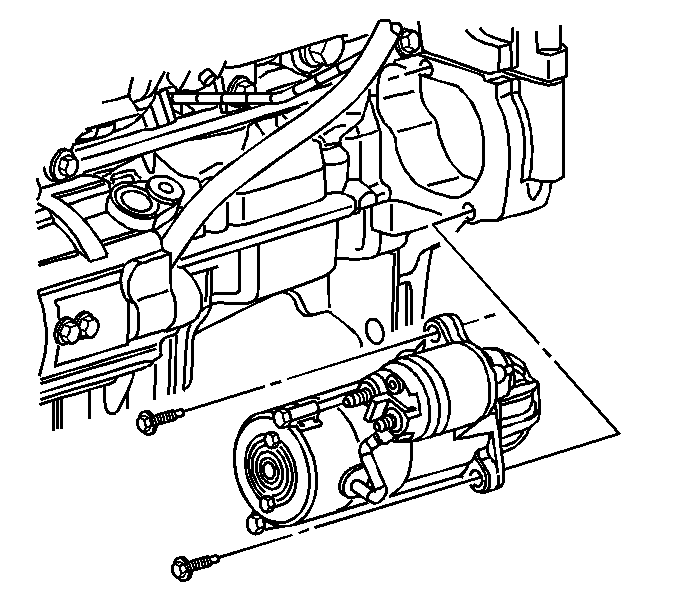
- Remove the starter.
- If applicable, remove the torque converter to flywheel bolts.
- Remove the transmission to engine bolts.
- Separate the engine from the transmission.
- If applicable, remove the clutch pressure plate and disk.
- Remove the following components:
| • | Thermostat housing and feed pipe |
- Remove the engine from the engine lift.
Installation Procedure
- Attach the engine lift hoist to the engine lift hooks.
- Install the following components:
- If applicable, install the clutch pressure plate and disk.
- Align the engine to the transmission.
Notice: Refer to Fastener Notice in the Preface section.
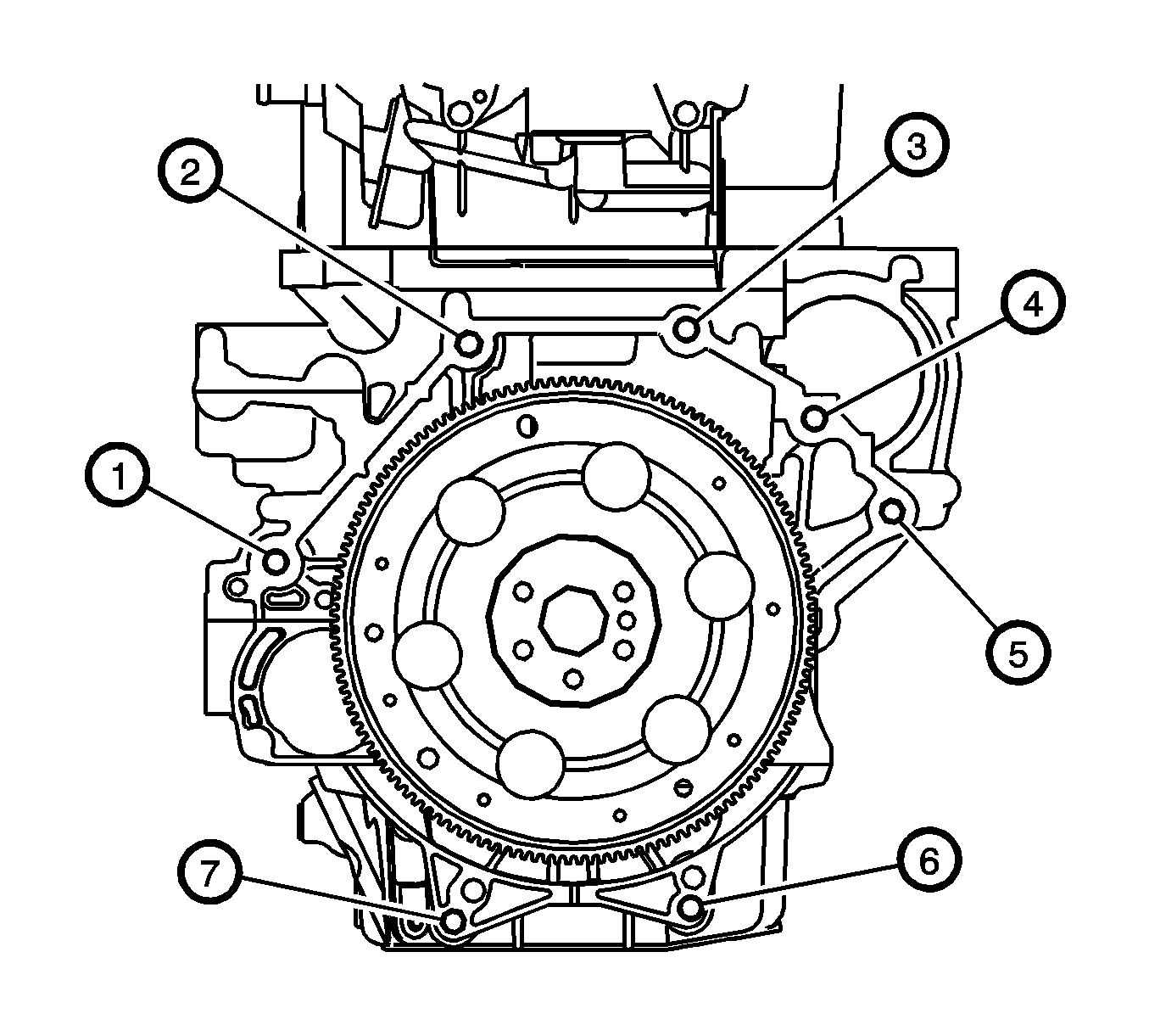
Important: The number 3 bolt location is not used.
- Secure the engine to the transmission.
Tighten
Tighten the transmission to engine bolts to 75 N·m (55 lb ft).
- If applicable, install the torque converter bolts.
Tighten
Tighten the bolts to 60 N·m (44 lb ft).

- Install the starter. Refer to
Starter Motor Replacement
.
- Remove the engine lift from the engine.
- Raise and position the frame and powertrain assembly to the vehicle.
- Hand start all the frame bolts while aligning the frame to the paint marks.
- Tighten the frame bolts.
Tighten
Tighten the frame bolts to 100 N·m (74 lb ft plus 180 degrees).
- Remove the lift table.

- Connect the drive axles to the steering knuckles. Refer to
Wheel Drive Shaft Replacement
.

- Connect the lower control arm to the steering knuckle. Refer to
Lower Control Arm Replacement
.

- Connect the intermediate steering shaft to the steering gear. Refer to
Steering Gear Replacement
.

- Connect the outer tie rod ends to the steering knuckles. Refer to
Rack and Pinion Outer Tie Rod End Replacement
.

- Connect the stabilizer links to the stabilizer bar. Refer to
Stabilizer Shaft Link Replacement
.

- Install the side transmission mount. Refer to the following:

- Install the engine mount. Refer to
Engine Mount Replacement
.
- Remove the wood blocks between the powertrain and frame.
- Connect the transmission shift cable to the transmission.
- Connect the transmission harness connector.
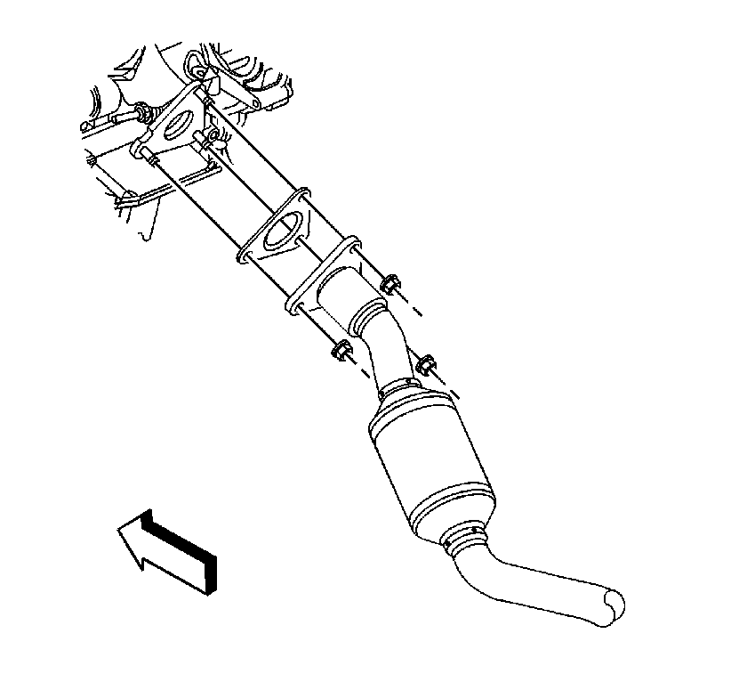
- Connect the exhaust takedown pipe to the exhaust manifold.
Tighten
Tighten the nuts to 30 N·m (22 lb ft).
- Connect the generator harness connectors.
Tighten
Tighten the generator terminal nut to 20 N·m (15 lb ft).

- Connect the starter harness connectors (3, 4, 5).
Tighten
| • | Tighten the battery terminal nut to 17 N·m (13 lb ft). |
| • | Tighten the S-terminal nut to 3 N·m (27 lb in). |
- Install the AC compressor to the engine. Refer to
Air Conditioning Compressor Replacement
.
- Install the engine drive belt. Refer to
Drive Belt Replacement
.
- Connect the following harness connectors:
| • | Ignition coil and module assembly |
| • | Engine temperature sensor |

- Install the inlet heater hose (1) and outlet heater hose (2). Refer to
Heater Inlet Hose Replacement
and
Heater Outlet Hose Replacement
.
- Install the radiator outlet hose. Refer to
Radiator Inlet Hose Replacement
.
- Connect the fuel line to the fuel rail. Refer to
Metal Collar Quick Connect Fitting Service
.
- Connect the brake booster hose at the brake booster.

- Release the cooling module from the upper body structure.
- Install the air inlet duct and resonator. Refer to
Air Cleaner Outlet Resonator Replacement
.
- Connect the negative battery cable. Refer to
Battery Negative Cable Disconnection and Connection
.
- Fill the engine with engine oil to the proper level. Refer to
Fluid and Lubricant Recommendations
.
- Fill the cooling system. Refer to
Cooling System Draining and Filling
.
- Road test the vehicle.


