Removal Procedure
Notice: Before removing the transmission and the clutch housing assembly from the engine, the engine must be supported so as to prevent the vapor blow pipe assembly (located at the rear of the engine) from making contact with and damaging the dash panel.
- Raise and support the vehicle. Refer to Section 0A.
- Remove the exhaust system. Refer to General Exhaust System Replacement in Engine Exhaust.
- Remove the transmission. Refer to Transmission Removal in Manual Transmission.
- Disconnect the wire harness ground connector from the flywheel housing to engine stud.
- Remove the clutch actuator cylinder from the flywheel housing and move aside. Refer to Clutch Actuator Cylinder Replacement .
- Remove the flywheel housing cover.
- Align the fork on the two flats of the release bearing and push the fork away from the bearing. A twisting motion will help.
- Remove the flywheel housing from the engine block.
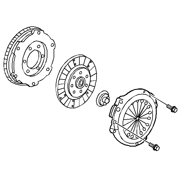
- Mark the alignment of the clutch pressure plate cover and the flywheel.
- Remove the clutch pressure plate to the flywheel bolts evenly, one turn at a time, until the spring pressure is released.
- Remove the clutch pressure plate and the clutch disc.
- Inspect the pressure plate and the flywheel for damage.
Notice: Do not allow the clutch actuator cylinder to hang by the hydraulic hoses. This may damage the clutch hydraulic hoses.
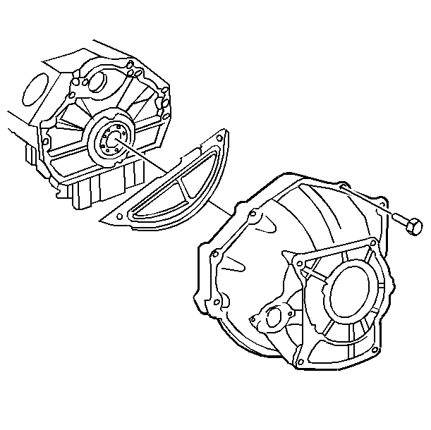
Important: There is an aluminum spacer plate located between the flywheel housing and the engine; and between the flywheel housing cover and the transmission.
Excessive clutch pressure plate wear may require ball stud locking screw removal. Excessive plate wear may also require loosening the ball stud in order to disengage the fork and the housing.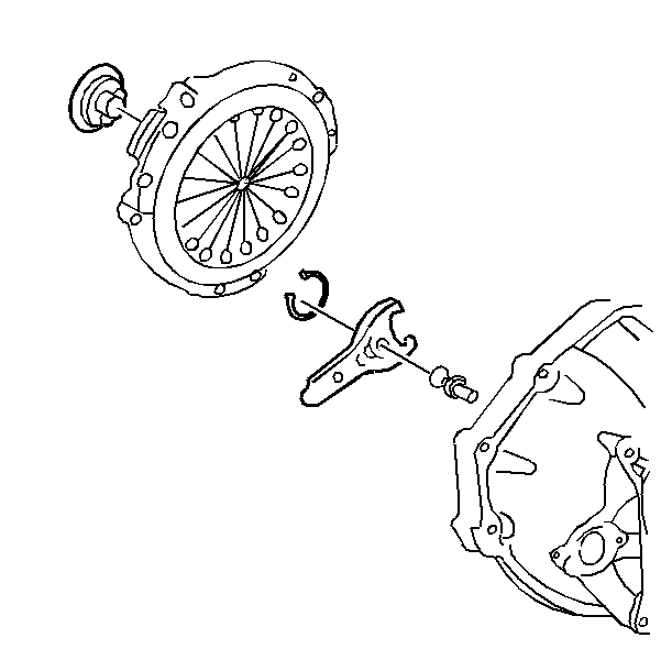
Notice: Failure to release clutch drive plate bolts uniformly may cause damage to the clutch drive plate and/or flywheel.
Installation Procedure
Tools Required
J 38836 Pilot Bushing Installer/Clutch Alignment Arbor
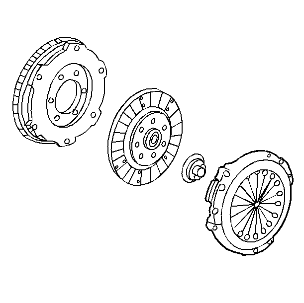
- Use the J 38836 in order to install the clutch pressure plate and the clutch disc.
- Install the clutch pressure plate to the flywheel bolts.
- Position the flywheel housing to the engine block, engaging the fork onto the release bearing. Ensure that the aluminum spacer is in place.
- Install the bolts retaining the flywheel housing to the engine block.
- Tighten the flywheel housing to the engine block bolts to 50 N·m (37 lb ft).
- Tighten the ball stud to 45 N·m (33 lb ft).
- Tighten the clutch fork ball stud locking screw 15 N·m (11 lb ft).
- Install the wiring harness ground connections.
- Install the flywheel housing cover and the bolts.
- Install the clutch actuator cylinder. Refer to Clutch Actuator Cylinder Replacement .
- Install the transmission. Refer to Transmission Installation in Manual Transmission.
- Install the exhaust system. Refer to General Exhaust System Replacement in Engine Exhaust.
- Lower the vehicle.
Important: Align the reference marks on the clutch pressure plate and the flywheel. This will help to retain proper balance.

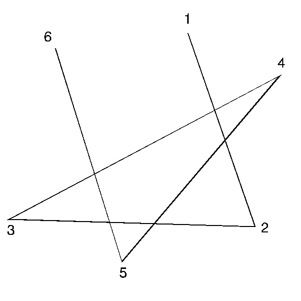
Tighten
Tighten the clutch pressure plate to the flywheel bolts, in sequence,
to 41 N·m (30 lb ft). Tighten the bolts one turn
at a time until the spring pressure is built up.
Notice: Use the correct fastener in the correct location. Replacement fasteners must be the correct part number for that application. Fasteners requiring replacement or fasteners requiring the use of thread locking compound or sealant are identified in the service procedure. Do not use paints, lubricants, or corrosion inhibitors on fasteners or fastener joint surfaces unless specified. These coatings affect fastener torque and joint clamping force and may damage the fastener. Use the correct tightening sequence and specifications when installing fasteners in order to avoid damage to parts and systems.
Important: Ensure that the flywheel housing is properly positioned in the two engine dowel pins.
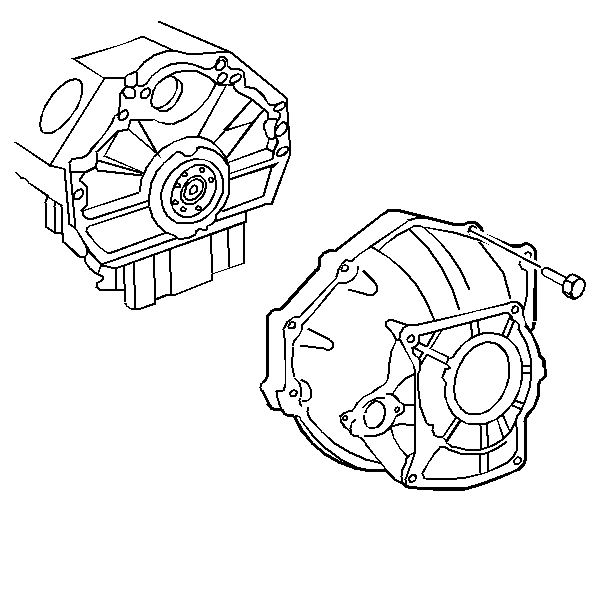
Tighten

Tighten
Tighten the bolts to 9 N·m (80 lb in).
Tighten
Tighten the actuator cylinder retaining nuts to 25 N·m
(18 lb ft).
Important: After installing the transmission and driveline support, check the air intake duct to the throttle body mating surface. If the air duct becomes dislodged from the throttle body a drivability problem may occur.
