Oil Cooler Hose/Pipe Replacement Front
Removal Procedure
Tools Required
J 41803 Engine Support Fixture
- Position the front wheels straight ahead, then lock the steering column.
- Disconnect the negative battery cable. Refer to
Caution: Unless directed otherwise, the ignition and start switch must be in the OFF or LOCK position, and all electrical loads must be OFF before servicing any electrical component. Disconnect the negative battery cable to prevent an electrical spark should a tool or equipment come in contact with an exposed electrical terminal. Failure to follow these precautions may result in personal injury and/or damage to the vehicle or its components.
in General Information. - Raise and suitably support the vehicle. Refer to Lifting and Jacking the Vehicle in General Information.
- Have a drain pan ready to catch fluid.
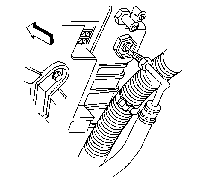
- Disconnect the transmisson oil cooler (TOC) front upper pipe fitting from the radiator, then cap the hose fitting.
- Disconnect the TOC front lower pipe fitting from the radiator, then cap the hose fitting.
- Drain the engine cooling system. Refer to Cooling System Draining and Filling in Engine Cooling.
- Lower the vehicle and leave it on the hoist.
- Discharge the A/C system. Refer to Evacuation in HVAC Systems with A/C - Manual.
- Disconnect the A/C compressor hose and the A/C evaporator hose from the A/C condenser, then cap or plug the hoses. Refer to Condenser in HVAC Systems with A/C - Manual.
- Remove the air intake duct and the upper radiator support. Refer to Radiator Support Replacement in Engine Cooling.
- Disconnect the inlet and outlet radiator hose clamps from the radiator.
- Disconnect the inlet and outlet radiator hoses from the radiator.
- Remove the air cleaner housing and the air intake shroud. Refer to Air Filter Element and Air Cleaner Assembly in Engine Controls.
- Carefully pivot the A/C condenser and the radiator forward and tie off to support.
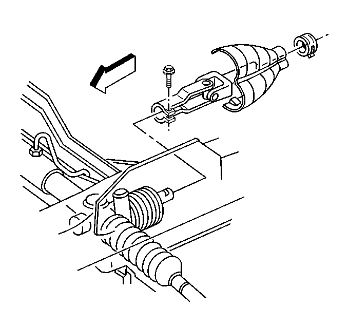
- Remove the intermediate shaft lower coupling shield.
- Remove the intermediate shaft lower coupling bolt.
- Disconnect the intermediate shaft lower coupling from the power steering (P/S) gear.
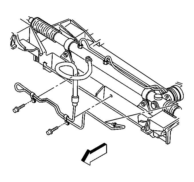
- Remove the P/S cooler retaining bolts.
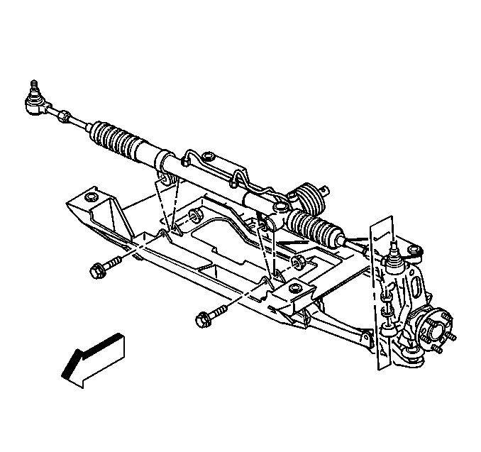
- Remove the P/S gear mounting bolts and nuts.
- Release the P/S gear and cooler from the front suspension crossmember, then slave forward.
- Remove the A/C compressor bracket. Refer to Compressor in HVAC Systems with A/C - Manual.
- Remove the generator from the accessory mounting bracket. Refer to Generator Replacement in Engine Electrical.
- Install and support the engine with the J 41803 .
- Remove the RH engine mount (with bracket). Refer to Engine Mount Replacement in Engine Mechanical.
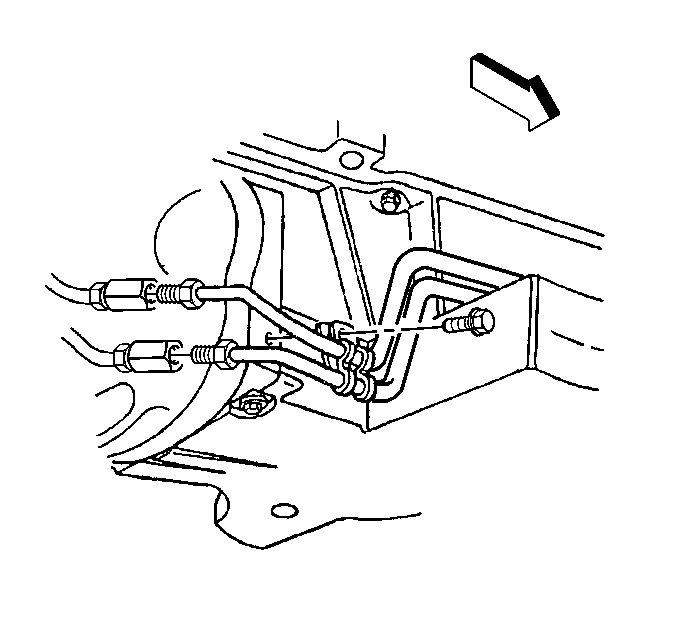
- Remove the TOC front pipe front clip.
- Raise the vehicle.
- Remove the TOC front pipe front retaining clamp bolt and retaining clamp.
- Remove the TOC front pipe rear retaining clamp bolt and retaining clamp.
- Disconnect the TOC front pipe fittings from the junction fittings at the engine flywheel housing.
- Lower the vehicle, leave it slightly above the ground.
- Finesse the TOC front pipes out of the vehicle (through the top).




Installation Procedure
Tools Required
J 41803 Engine Support Fixture
- Install the transmission oil cooler (TOC) front pipes to the vehicle (through the top).
- Raise the vehicle.
- HAND-START and HAND-TIGHTEN the TOC front upper and lower pipe fittings to the junction fittings at the engine flywheel housing.
- Install the TOC front pipe rear retaining clamp and bolt.
- Install the TOC front pipe front retaining clamp and bolt.
- Lower the vehicle, leave it slightly above the ground.
- Install the TOC front pipe front clip.
- Install the RH engine mount (with bracket). Refer to Engine Mount Replacement in Engine Mechanical.
- Remove the J 41803 .
- Install the generator to the accessory mounting bracket. Refer to Generator Replacement in Engine Electrical.
- Install the A/C compressor bracket. Refer to Compressor in HVAC Systems with A/C - Manual.
- Position the power steering (P/S) gear and cooler to the front suspension crossmember.
- Install the P/S gear mounting bolts and nuts.
- Install the P/S cooler retaining bolts.
- Connect the intermediate shaft lower coupling to the power steering gear.
- Install the intermediate shaft lower coupling bolt.
- Install the intermediate shaft lower coupling shield.
- Carefully pivot the A/C condenser and the radiator back into position.
- Install the air intake shroud and the air cleaner housing. Refer to Air Filter Element and Air Cleaner Assembly in Engine Controls.
- Connect the inlet and outlet radiator hoses to the radiator.
- Connect the inlet and outlet radiator hose clamps to the radiator.
- Install the upper radiator support and the air intake duct. Refer to Radiator Support Replacement in Engine Cooling.
- Flush the TOC and TOC pipes. Refer to Transmission Fluid Cooler Flushing .
- HAND-START and HAND-TIGHTEN the TOC front lower pipe fitting to the radiator.
- HAND-START and HAND-TIGHTEN the TOC front upper pipe fitting to the radiator.
- Lower the vehicle.
- Connect the negative battery cable.
- Refill the engine cooling system. Refer to Cooling System Draining and Filling in Engine Cooling.
- Evacuate and charge the A/C system. Refer to Air Conditioning (A/C) Charging Using ACR4 in HVAC Systems with A/C - Manual.
- Check the transmission fluid level. Refer to Automatic Transmission Fluid Level Check/Fill .

Finesse the pipes into position.
Tighten
Tighten the transmission oil cooler front upper and lower pipe fittings
at the junction to 27 N·m (20 lb ft).
Notice: Use the correct fastener in the correct location. Replacement fasteners must be the correct part number for that application. Fasteners requiring replacement or fasteners requiring the use of thread locking compound or sealant are identified in the service procedure. Do not use paints, lubricants, or corrosion inhibitors on fasteners or fastener joint surfaces unless specified. These coatings affect fastener torque and joint clamping force and may damage the fastener. Use the correct tightening sequence and specifications when installing fasteners in order to avoid damage to parts and systems.
Tighten
Tighten the transmission oil cooler front pipe rear retaining clamp
bolt to 2.2 N·m (19 lb in).

Tighten
Tighten the transmission oil cooler front pipe front retaining clamp
bolt to 12 N·m (106 lb in).


Tighten
Tighten the power steering gear mounting nuts to 100 N·m
(74 lb ft).

Tighten
Tighten the power steering cooler retaining bolts to 11 N·m
(97 lb in).

Tighten
Tighten the intermediate shaft lower coupling bolt to 34 N·m
(25 lb ft).

Tighten
Tighten the transmission oil cooler front lower pipe fitting to the
radiator to 27 N·m (20 lb ft).

Tighten
Tighten the transmission oil cooler front upper pipe fitting to the
radiator to 27 N·m (20 lb ft).
Tighten
Tighten the negative battery cable bolt to 15 N·m (11 lb ft).
Oil Cooler Hose/Pipe Replacement Rear
Removal Procedure
- Raise and suitably support the vehicle. Refer to Lifting and Jacking the Vehicle in General Information.
- Remove the intermediate exhaust pipe. Refer to Intermediate Pipe in Engine Exhaust.
- Remove the RH muffler assembly. Refer to Muffler in Engine Exhaust.
- Remove the driveline tunnel closeout panel. Refer to Driveline Tunnel Closeout Panel in Propeller Shaft.
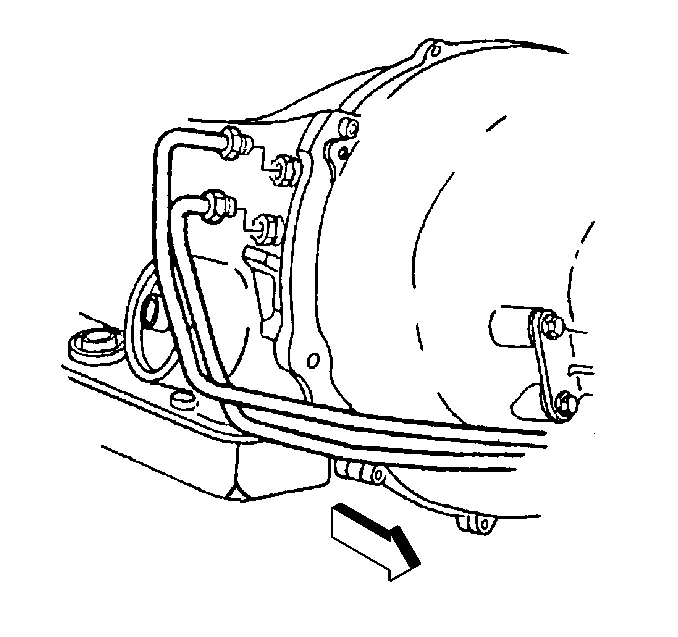
- Disconnect the transmission oil cooler (TOC) rear upper and lower pipe fittings from the junction fittings at the engine flywheel housing.
- Disconnect the TOC rear upper and lower pipe fittings from the transmission fittings.
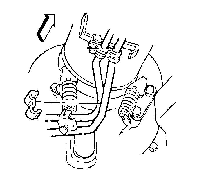
- Remove the TOC rear pipe rear clip.
- Remove the TOC rear pipe middle clip.
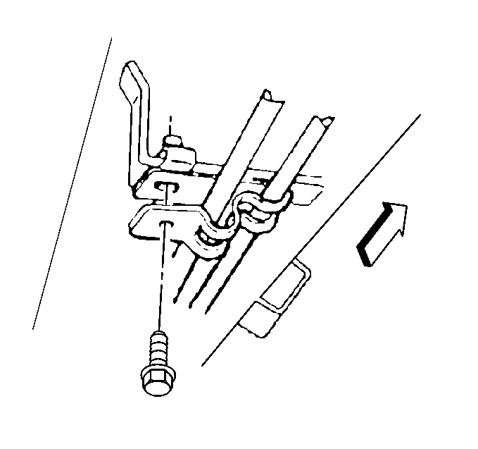
- Remove the TOC rear pipe front and rear clamp bolts and clamps.
- Remove the rear transmission oil cooler pipes.

Installation Procedure
- Install the transmission oil cooler (TOC) rear pipes into position.
- Install the TOC rear pipe front and rear retaining clamps and bolts.
- Install the TOC rear pipe middle clip.
- Install the TOC rear pipe rear clip.
- HAND-START and HAND-TIGHTEN the TOC rear upper and lower pipe fittings to the transmission fittings.
- HAND-START and HAND-TIGHTEN the TOC rear upper and lower pipe fittings to the junction fittings at the engine flywheel housing.
- Install the driveline tunnel closeout panel. Refer to Driveline Tunnel Closeout Panel in Propeller Shaft.
- Install the RH muffler assembly. Refer to Muffler in Engine Exhaust.
- Install the intermediate exhaust pipe. Refer to Intermediate Pipe in Engine Exhaust.
- Flush the transmission oil cooler and oil cooler pipes. Refer to Transmission Fluid Cooler Flushing .
- Check the transmission fluid level. Refer to Automatic Transmission Fluid Level Check/Fill .
- Lower the vehicle.

Tighten
Tighten the transmission oil cooler rear pipe front and rear retaining
clamp bolts to 12 N·m (106 lb in).
Notice: Use the correct fastener in the correct location. Replacement fasteners must be the correct part number for that application. Fasteners requiring replacement or fasteners requiring the use of thread locking compound or sealant are identified in the service procedure. Do not use paints, lubricants, or corrosion inhibitors on fasteners or fastener joint surfaces unless specified. These coatings affect fastener torque and joint clamping force and may damage the fastener. Use the correct tightening sequence and specifications when installing fasteners in order to avoid damage to parts and systems.


Tighten
Tighten the transmission oil cooler rear upper and lower pipe fittings
to the transmission fittings to 27 N·m (20 lb ft).

Tighten
Tighten the transmission oil cooler rear upper and lower pipe fittings
at the junction to 27 N·m (20 lb ft).
