For 1990-2009 cars only
Removal Procedure
Tools Required
| • | J 41688 Lock Plate Compressor |
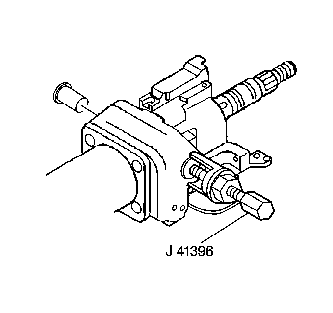
| • | J 21854-01 Pivot Pin Remover |
- Remove the SIR coil assembly. Refer to Inflatable Restraint Steering Wheel Module Coil Replacement - Off Vehicle .
- Remove the T/S And Multifunction Switch. Refer to Turn Signal and Multifunction Switch Assembly - Off Vehicle .
- Remove the upper tilt head components. Refer to Upper Tilt Head Components .
- Remove the tilt spring. Refer to Tilt Spring - Off Vehicle .
- Use the J 21854-01 to remove the two pivot pins.
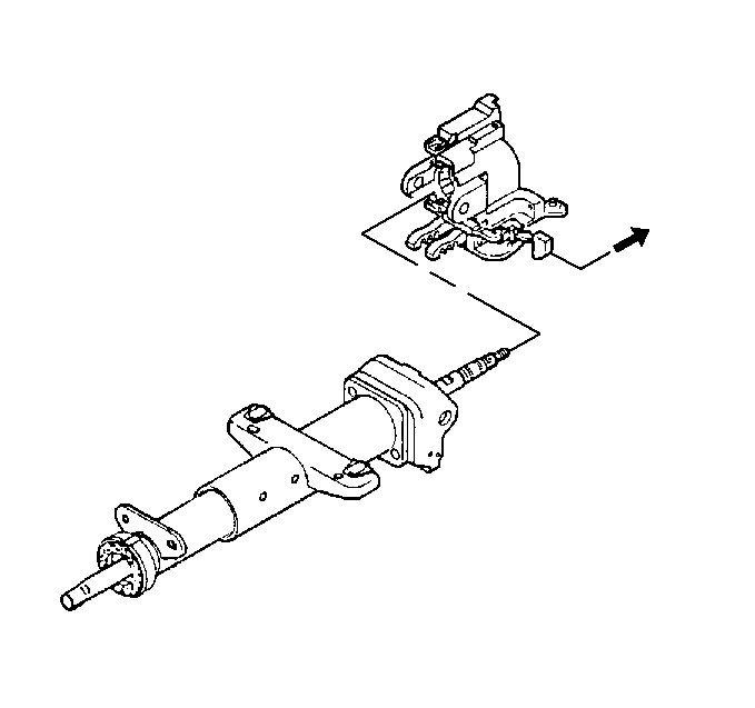
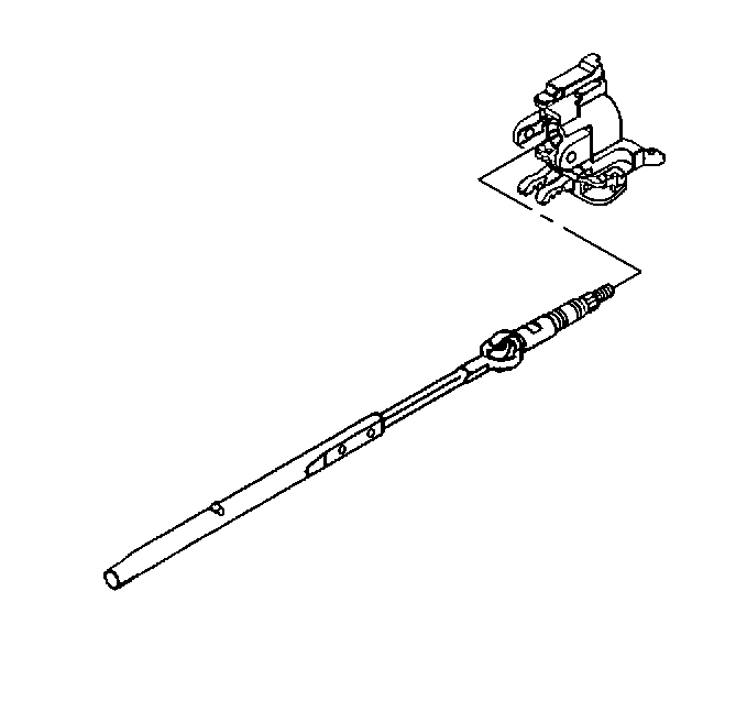
- Perform the following steps to remove the steering column tilt head assembly:
- Remove the steering column tilt head assembly.


| 6.1. | Mark the race and upper shaft assembly and mark the lower steering shaft assembly to ensure proper assembly. Failure to assemble properly will cause steering wheel to be turned 180 degrees. |
| 6.2. | Pull the tilt arm to disengage the steering wheel lock shoes from the dowel pins in the steering column support assembly. |

Installation Procedure
- Perform the following steps to install the steering column tilt head assembly:
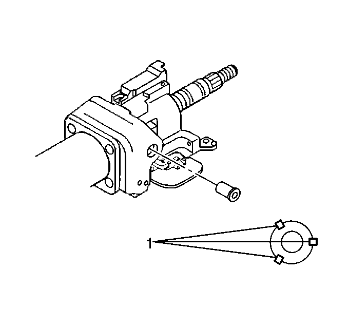
- Perform the following steps to install the two pivot pins (1):
- Install the tilt spring. Refer to Tilt Spring - Off Vehicle .
- Install the upper tilt head components. Refer to Upper Tilt Head Components .
- Install the SIR coil assembly. Refer to Inflatable Restraint Steering Wheel Module Coil Replacement - Off Vehicle .

| 1.1. | Use the tilt lever position to lock the shoes to the down pins. |
| 1.2. | Rotate the head assembly until the holes for the pivot pins line up. |

| 2.1. | Lubricate with lithium grease. |
| 2.2. | Press the pins until firmly seated in two places. |
| 2.3. | Stake the pins in three locations. |
