Removal Procedure
Notice: Whenever the Instrument Panel Cluster (IPC) is removed from the vehicle, DO NOT set the IPC on its face for more than 15 minutes or damage to the fluid filled air core gages may result.
- Remove the instrument panel cluster (IPC) from the vehicle. Refer to Instrument Cluster Replacement .
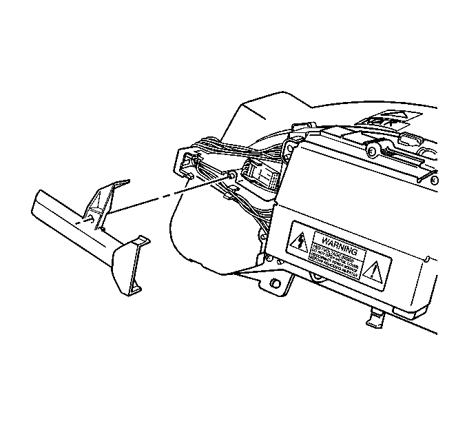
- Remove the ultra-violet (UV) inverter wiring covers; unsnap.
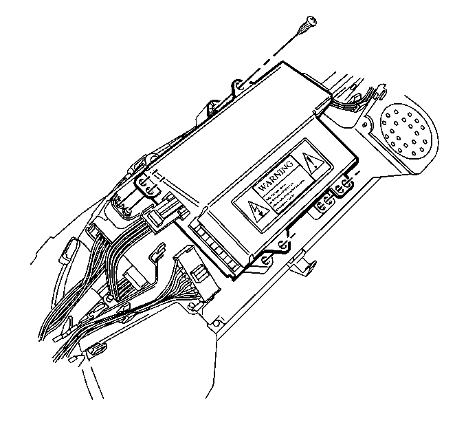
- Disconnect the UV inverter electrical connectors.
- Remove the UV inverter mounting screws.
- Remove the UV inverter.
- Disconnect the electrical connectors from the IPC printed circuit board.
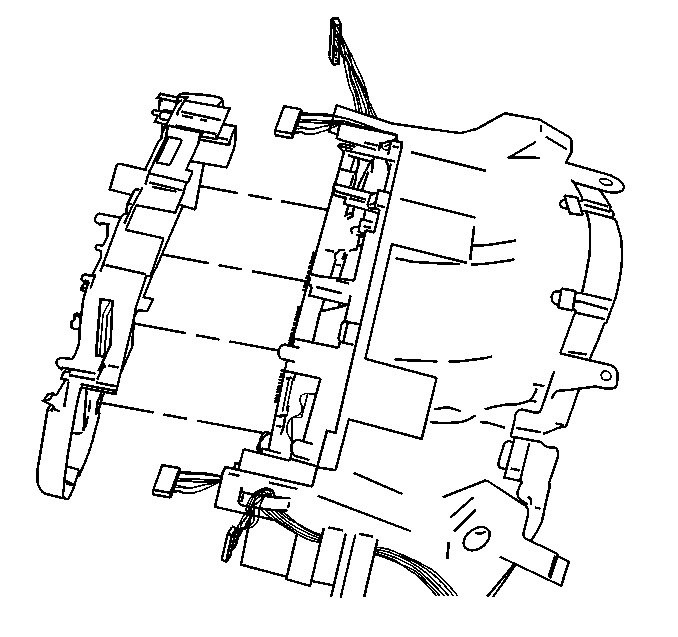
- Remove the IPC rear cover retaining screws.
- Remove the rear cover; unsnap.
- Disconnect the (side) electrical connector from the circuit board.
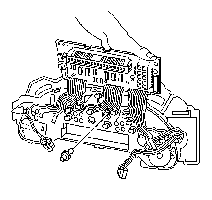
- Remove the circuit board retaining screws.
- Tilt the circuit board up slightly.
- Unsnap the circuit board tabs and lift slowly.
- Disconnect the chime connector from the circuit board.
- Tilt the circuit board out of the way.
- Twist to remove the appropriate bulb/socket from the IPC.


Tilt the board slowly and make sure the flat wires do not become kinked or loose.
Installation Procedure
- Twist to install the bulb/socket to the IPC.
- Tilt the circuit board back toward its mounting position.
- Connect the chime connector to the circuit board.
- Tilt the circuit board the rest of the way to its mounting position.
- Snap the circuit board tabs into place.
- Install the circuit board retaining screws.
- Connect the (side) electrical connector to the circuit board.
- Position the IPC rear cover.
- Snap the IPC rear cover into place.
- Install the IPC rear cover retaining screws.
- Connect the electrical connectors to the circuit board.
- Install the UV inverter to the IPC rear cover.
- Install the UV inverter mounting screws.
- Connect the UV inverter electrical connectors.
- Install the UV inverter wiring covers.
- Install the IPC to the vehicle. Refer to Instrument Cluster Replacement .

Tilt the board slowly, and make sure the flat wires do not become kinked or loose.

Tighten
Tighten the IPC rear cover retaining screws to 0.7 N·m
(6 lb in).
Notice: Use the correct fastener in the correct location. Replacement fasteners must be the correct part number for that application. Fasteners requiring replacement or fasteners requiring the use of thread locking compound or sealant are identified in the service procedure. Do not use paints, lubricants, or corrosion inhibitors on fasteners or fastener joint surfaces unless specified. These coatings affect fastener torque and joint clamping force and may damage the fastener. Use the correct tightening sequence and specifications when installing fasteners in order to avoid damage to parts and systems.

Align the UV inverter onto the rear cover alignment pins.
Tighten
Tighten the UV inverter mounting screws to 0.7 N·m (6 lb in).

| 15.1. | Align the covers on the alignment pins. |
| 15.2. | Snap the covers into place. |
