For 1990-2009 cars only
Removal Procedure
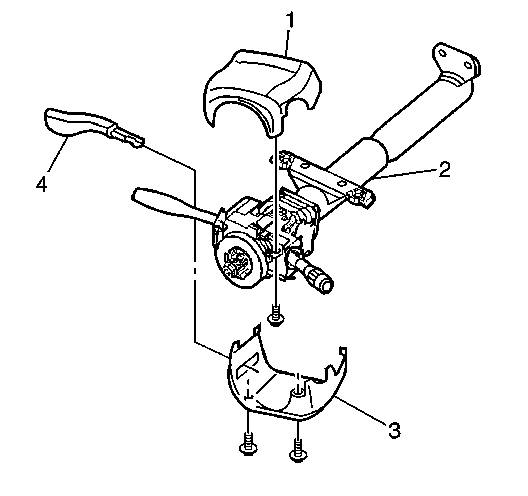
- Remove the tilt wheel lever (4). Refer to Tilt Wheel Lever .
- Remove the steering wheel. Refer to Steering Wheel Replacement .
- Remove the driver's side knee bolster trim panel. Refer to Driver Knee Bolster Panel Replacement in Instrument Panel, Gages and Console.
- Separate and remove the upper (1) and the lower (3) steering column covers.
- Disconnect the electrical connectors from the wiring harness.
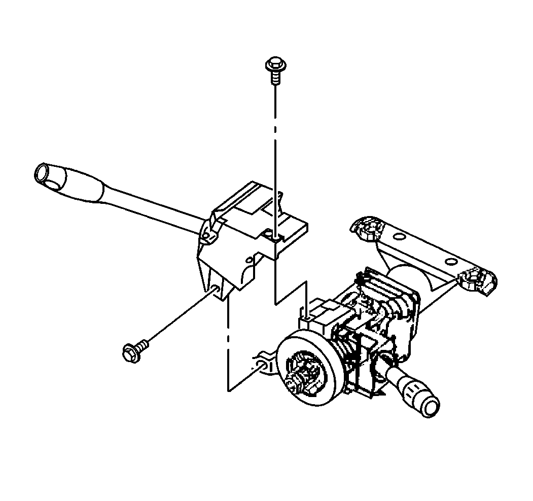
- Remove the torx screws retaining the multifunction switch to the column.
- Remove the multifunction switch from the column.


Installation Procedure
- Install the multifunction switch onto the column.
- Install the multifunction switch retaining screws (torx screws) into the switch.
- Connect the electrical connectors into the wiring harness.
- Connect the upper (1) and lower (3) steering column covers.
- Install the driver's side knee bolster and trim panel. Refer to Driver Knee Bolster Panel Replacement in Instrument Panel, Gages and Console.
- Install the steering wheel. Refer to Steering Wheel Replacement .
- Install the tilt wheel lever (4). Refer to Tilt Wheel Lever .

Tighten
Tighten the multifunction switch retaining screws to 6 N·m
(53 lb in).

