Fuel Tank Draining W/FFS
Tools Required
J 45004 Fuel Tank Drain Hose
Caution: Never drain or store fuel in an open container. Always use an approved fuel storage container in order to reduce the chance of fire or explosion.
Notice: Drain the fuel tank with a hose which has a 13 mm (0.5 in) or smaller diameter in order to prevent the drain hose from getting stuck inside the fuel tank filler neck pipe check valve. Damage to the check valve may result.
Notice: Drain the fuel from the complete system, including injector nozzle(s), the fuel pump, all fuel pipes, and the fuel tank if a vehicle is to be stored for any appreciable length of time. Draining the fuel will prevent the formations of fuel system deposits.
- Relieve the fuel system pressure. Refer to Fuel Pressure Relief .
- Remove the fuel tank filler pipe cap.
- Drain the fuel through the fuel tank filler pipe using a hand or air operated fuel pump device and the J 45004 .
- Remove the driveline support assembly. Refer to Driveline Support Assembly Replacement in Propeller Shaft.
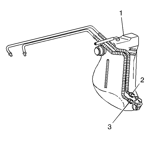
- Remove the crossover tube/hose (1) from the clip (2) located above the transmission.
- Remove the crossover tube/hose from the RH fuel tank. Refer to Fuel Tank Crossover Tube Replacement .
- Drain the fuel through the fuel tank crossover connection (1) using a hand or air operated fuel pump device and the J 45004 .
Fuel Tank Draining W/O FFS
Tools Required
| • | J 34730-1A Fuel Pressure Gauge |
| • | J 37088-A Tool Set, Fuel Line Quick Connect Separator |
- Relieve the fuel system pressure. Refer to Fuel Pressure Relief .
- Raise the vehicle. Refer to Lifting and Jacking the Vehicle in General Information.
- Remove both of the rear wheel and tire assemblies. Refer to Tire and Wheel Removal and Installation in Tires and Wheels.
- Attach a length of flexible fuel hose to an air operated pump device.
- Position an approved drain container under the left tank fuel sender.
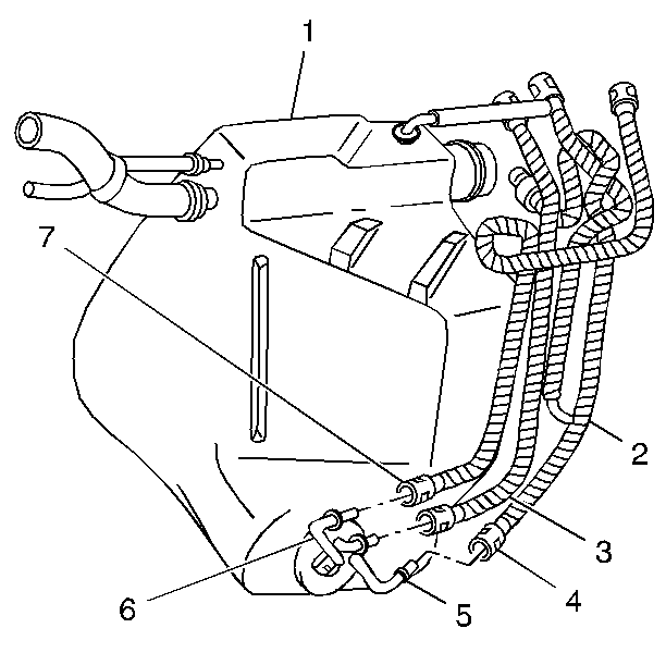
- Wrap a shop towel around the left tank fuel feed rear pipe (4).
- Disconnect the fuel feed rear pipe (4) at the left tank fuel sender using J 37088-A .
- Attach the flexible fuel hose from the pump device to the fuel feed pipe nipple (5) using a screw-type clamp.
- Drain the left fuel tank until no fuel comes out.
- Disconnect the pump device from the left tank fuel feed pipe nipple (5).
- Cap the fuel feed pipe nipple (5) and the fuel feed rear pipe (4).
- Position an approved drain container under the right tank fuel sender.
- Wrap a shop towel around the auxiliary fuel return rear pipe that connects the (3) jet pump to the left tank at the right fuel sender.
- Disconnect the auxiliary fuel return rear pipe that connects the (3) jet pump to the left tank at the right tank fuel sender using J 37088-A .
- Attach the flexible fuel hose from the pump device to the auxiliary fuel return rear pipe (3) nipple using a screw type clamp.
- Drain the right tank until no fuel comes out.
- Disconnect the pump device from the right tank fuel sender nipple.
- Cap the auxiliary fuel return rear pipe nipple (3) and the auxiliary fuel return rear pipe.

Caution: Always wear safety goggles when working with fuel in order to protect the eyes from fuel splash.

