Removal Procedure
- Disable the SIR system. Refer to SIR Disabling and Enabling in SIR.
- Remove the console. Refer to Console Replacement .
- Remove the I/P accessory trim plate. Refer to Instrument Panel Accessory Trim Plate Replacement .
- Remove the I/P compartment. Refer to Instrument Panel Compartment Replacement .
- Remove the driver knee bolster trim panel. Refer to Driver Knee Bolster Panel Replacement .
- Remove the I/P upper trim pad. Refer to Instrument Panel Upper Trim Pad Replacement .
- Remove the outlet duct from the right side window defogger.
- Release the I/P harness retainer from the passenger SIR bracket along the hinge pillar.
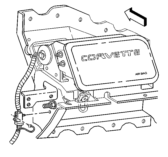
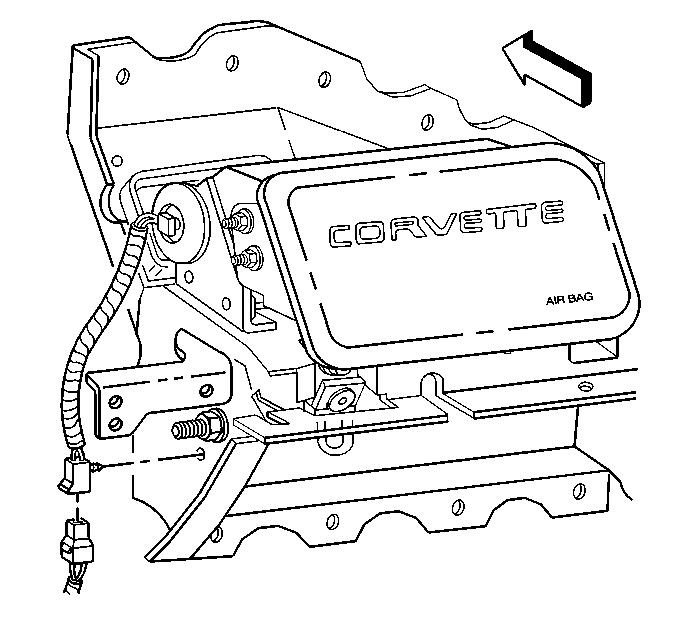
- Remove the connector position assurance (CPA) from the SIR module electrical connector.
- Release the electrical connector retainer from the SIR bracket.
- Disconnect the SIR module electrical connector.
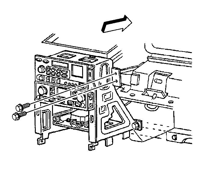
- Mark the location of the knee bolster bracket. Refer to Instrument Panel Disassembly Precautions .
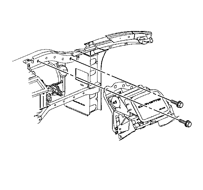
- Remove the bolts retaining the knee bolster bracket to the center support bracket.
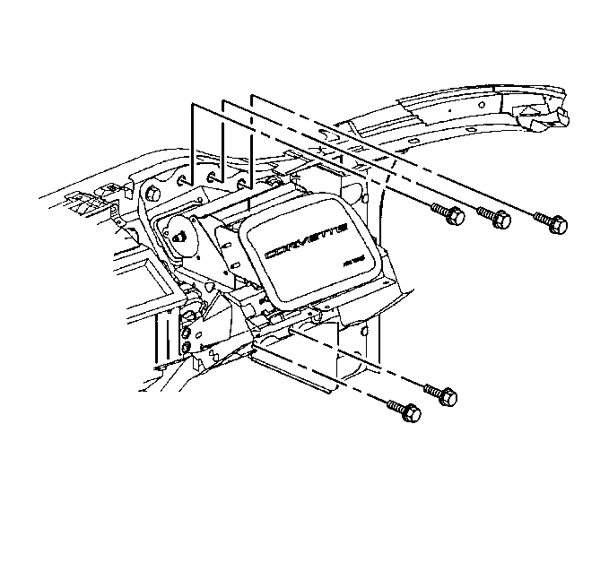
- Mark the location of the SIR bracket. Refer to Instrument Panel Disassembly Precautions .
- Remove the bolts mounting the SIR bracket to the I/P lower support beam.
- Remove the bolts mounting the SIR bracket to the I/P upper support beam.
- Remove the SIR bracket.
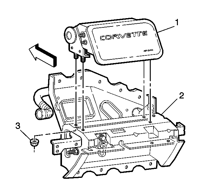
- Mark the location of the SIR module in the SIR bracket.
- Remove the SIR module retaining nuts (3).
- Remove the SIR module (1) from the SIR bracket (2).
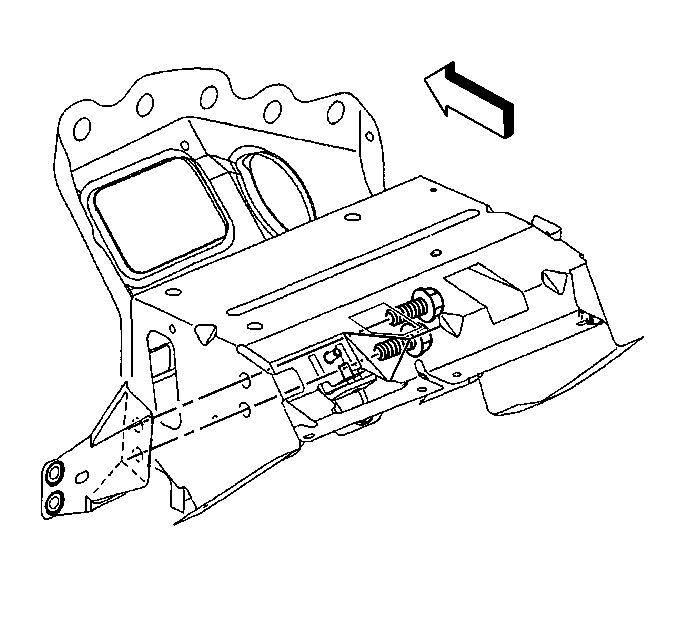
- Remove the mounting bolts from the knee bolster bracket.
- Remove the knee bolster bracket.
Caution: Refer to SIR Inflator Module Handling and Storage Caution in the Preface section.
Important: The following step must be performed to assure proper trim fit during installation.
Important: The following step must be performed to assure proper trim fit during installation.
Installation Procedure
- Install the knee bolster bracket into position as marked prior to removal.
- Install the retaining bolts which secure the knee bolster bracket to the SIR bracket.
- Install the SIR module (1) to the SIR bracket (2) as marked prior to removal.
- Install the SIR module retaining nuts (3).
- Install the SIR bracket into position as marked prior to removal.
- Install the bolts which secure the SIR bracket to the I/P upper and lower support beams.
- Position the knee bolster bracket to the center support bracket as marked prior to removal.
- Install the bolts which secure the knee bolster bracket to the center support bracket.
- Connect the SIR module electrical connector.
- Secure the electrical connector retainer to the SIR bracket.
- Install the CPA to the SIR module electrical connector.
- Secure the I/P harness retainer to the SIR bracket along the hinge pillar. Insert the I/P compartment lamp electrical connector down through the opening in the top of the SIR bracket.
- Install the right side window defogger outlet duct.
- Install the I/P upper trim pad. Refer to Instrument Panel Upper Trim Pad Replacement .
- Adjust the fit of the SIR module to the I/P upper trim pad, if necessary.
- Install the I/P compartment. Refer to Instrument Panel Compartment Replacement .
- Install the driver knee bolster trim panel. Refer to Driver Knee Bolster Panel Replacement .
- Install the I/P accessory trim plate. Refer to Instrument Panel Accessory Trim Plate Replacement .
- Install the console. Refer to Console Replacement .
- Enable the SIR system. Refer to SIR Disabling and Enabling in SIR.

Notice: Use the correct fastener in the correct location. Replacement fasteners must be the correct part number for that application. Fasteners requiring replacement or fasteners requiring the use of thread locking compound or sealant are identified in the service procedure. Do not use paints, lubricants, or corrosion inhibitors on fasteners or fastener joint surfaces unless specified. These coatings affect fastener torque and joint clamping force and may damage the fastener. Use the correct tightening sequence and specifications when installing fasteners in order to avoid damage to parts and systems.
Tighten
Tighten the bolts to 12 N·m (106 lb in).

Tighten
Tighten the nuts to 10 N·m (89 lb in).


Tighten
Tighten the bolts to 12 N·m (106 lb in).

Tighten
Tighten the bolts to 12 N·m (106 lb in).


