Tools Required
J 39400-A Halogen Leak Detector
Removal Procedure
- Recover the refrigerant from the A/C system. Refer to Refrigerant Recovery and Recharging .
- Drain the cooling system. Refer to Cooling System Draining and Filling in Engine Cooling.
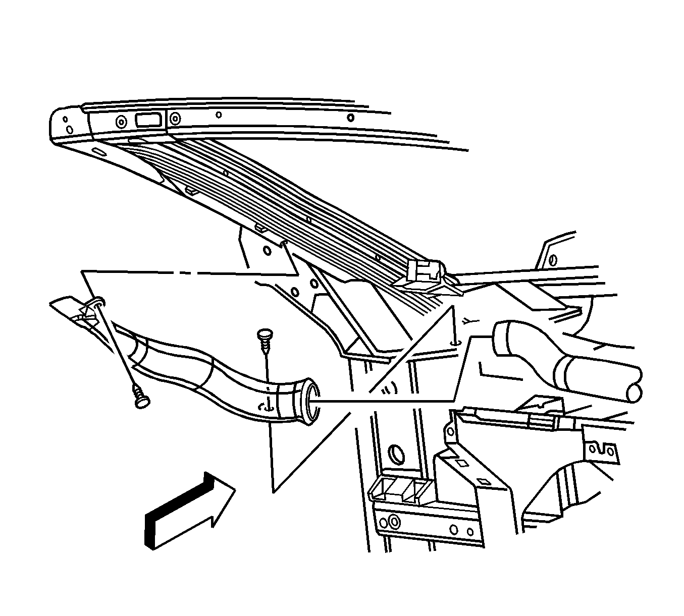
- Remove the heater pipe assembly . Refer to Heater Pipes Replacement .
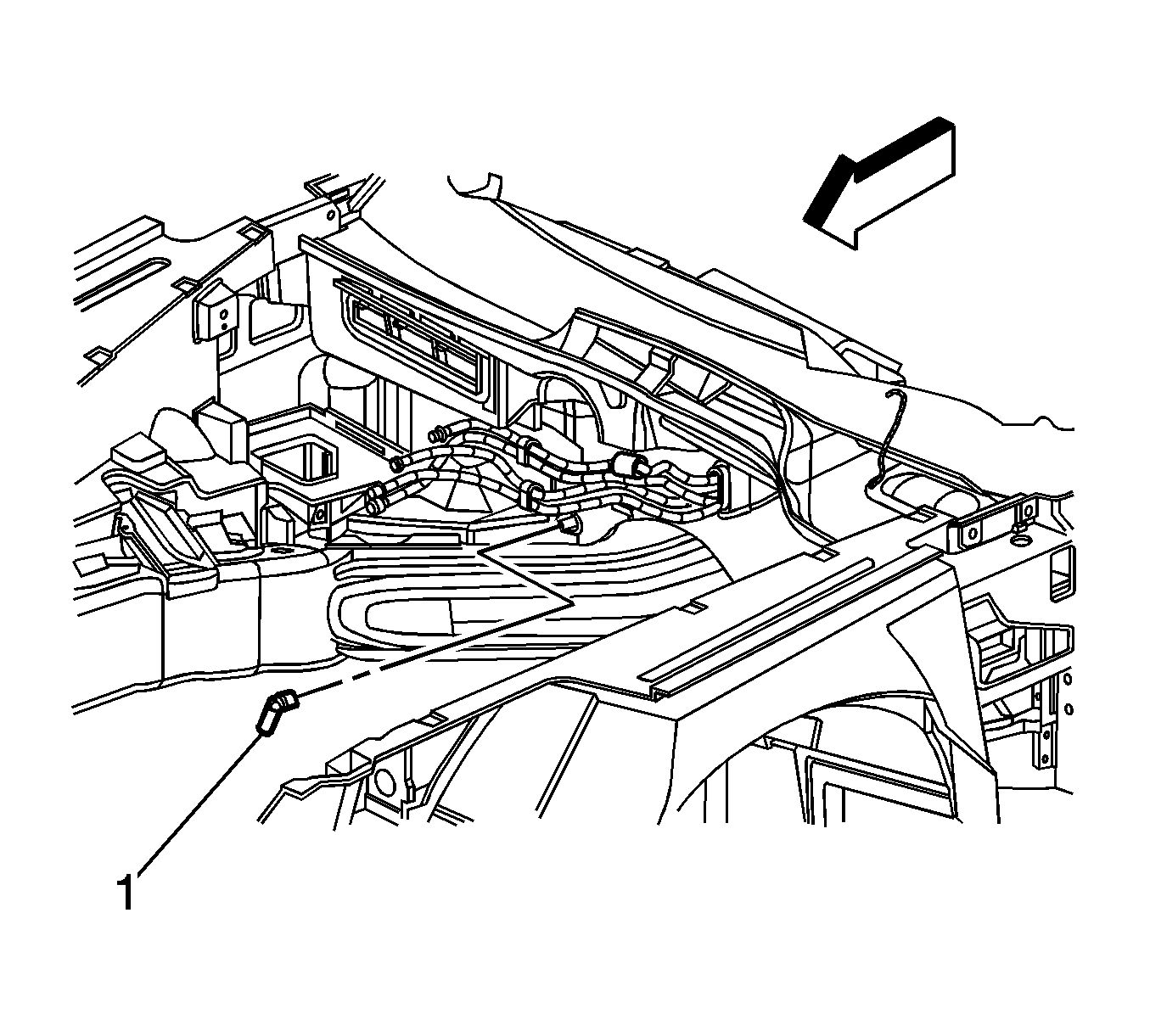
- Remove the evaporator drain tube (1) from the HVAC module.
- Remove the instrument panel (I/P) assembly. Refer to Instrument Panel Assembly Replacement in Instrument Panel, Gages, and Console.
- Remove the air distribution duct. Refer to Air Distributor Duct Replacement .
- Remove the retainers from the upper defogger duct on the left side window.
- Disconnect and remove the upper defogger outlet duct.
- Disconnect the head-up display (HUD) electrical connector.
- Remove the HUD retaining nuts.
- Remove the screw that secures the HUD to the steering column bracket.
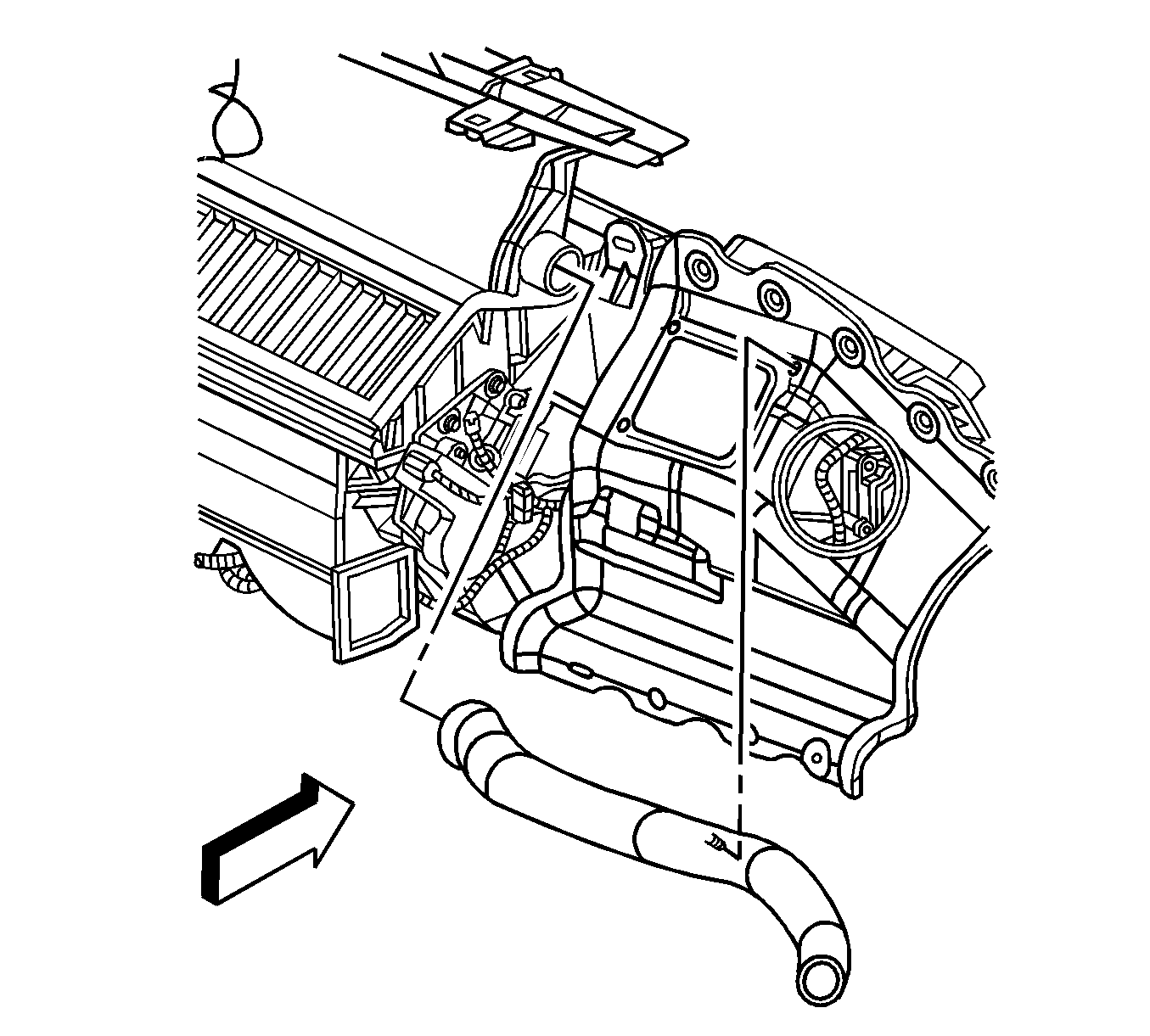
- Remove the retainer from the lower defogger outlet duct.
- Disconnect and remove the outlet duct from the defroster duct.
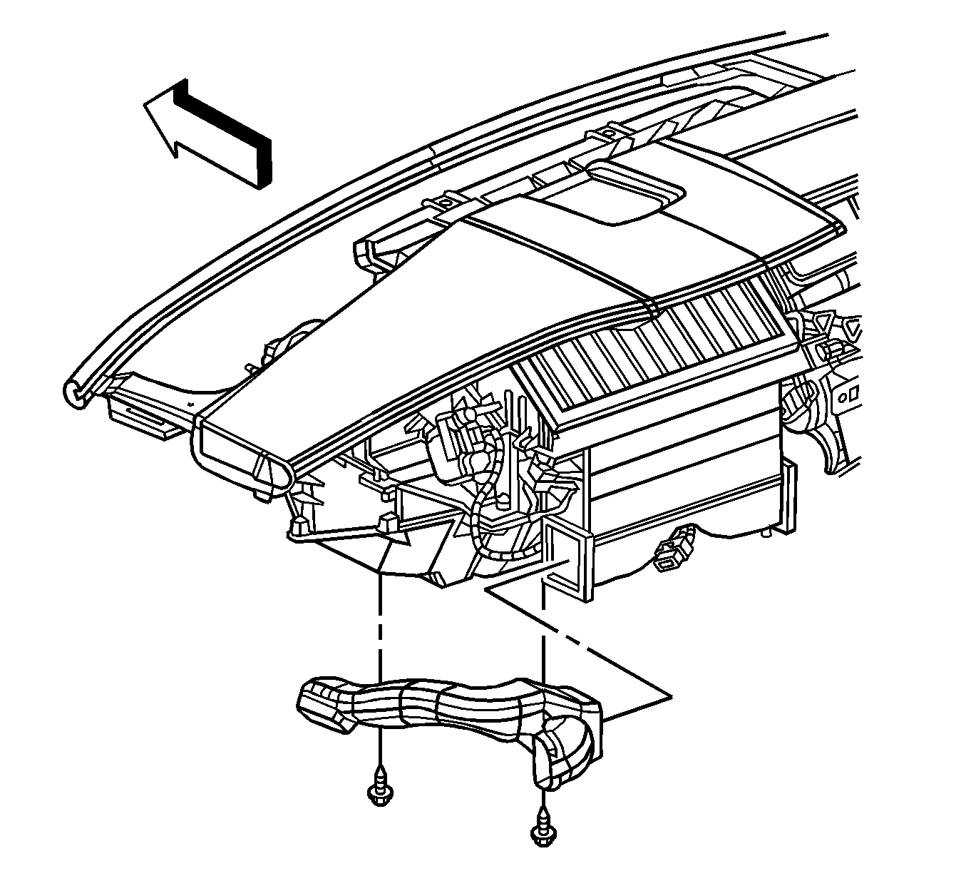
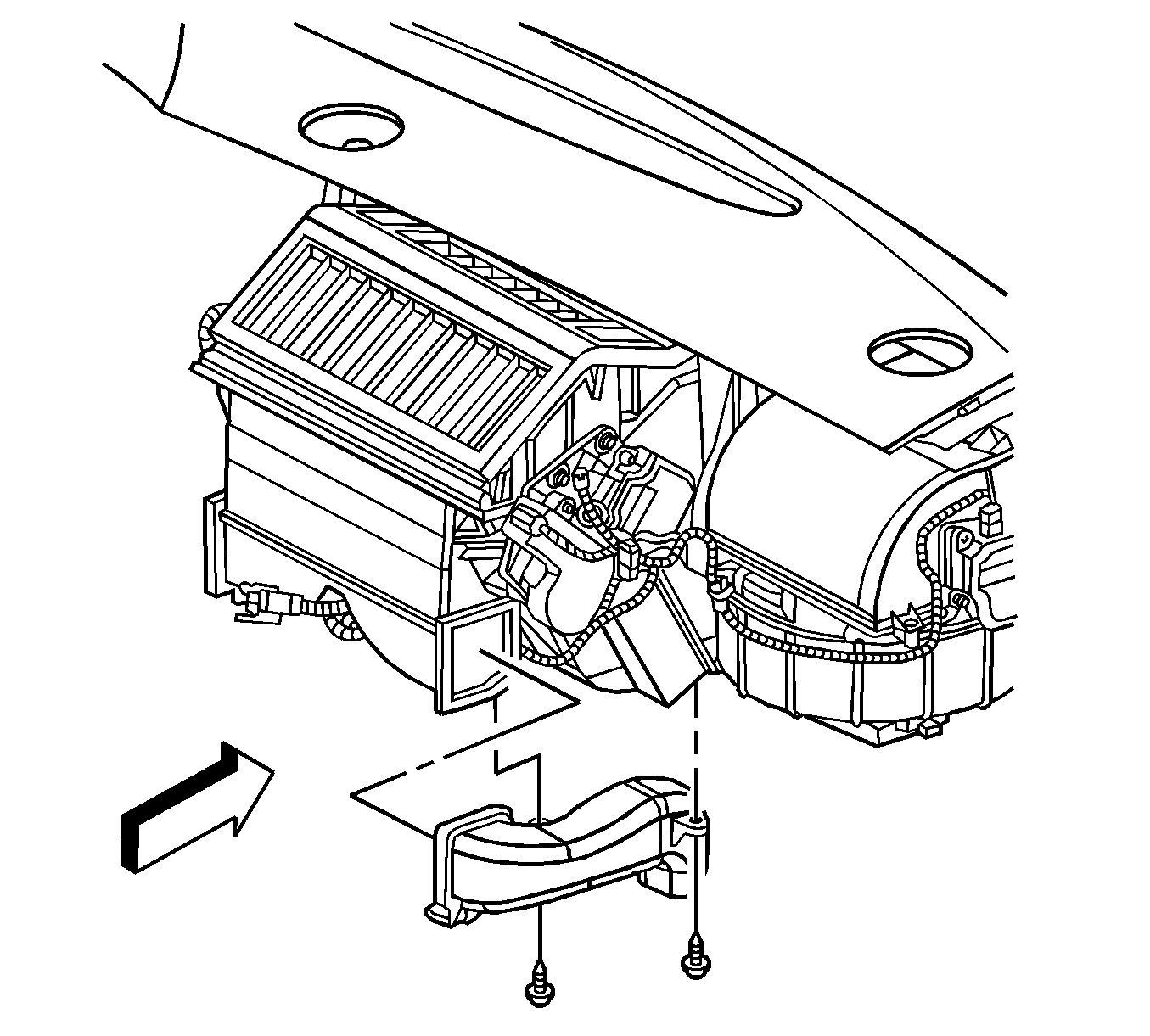
- Remove the retaining screws from the floor air outlet duct.
- Remove the outlet duct.
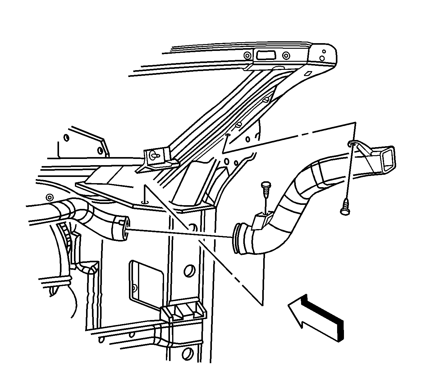
- Remove the retainers from the upper outlet duct on the right side window defogger.
- Disconnect and remove the defogger upper outlet duct from the defogger lower outlet duct.
- Disconnect the defogger lower outlet duct from the knee bolster bracket.
- Disconnect the defogger lower outlet duct from the defroster duct.
- Remove the defogger lower outlet duct.
- Remove the SIR bracket. Refer to Instrument Panel Inflatable Restraint Module Bracket Replacement in Instrument Panel, Gages, and Console.
- Remove the retaining screws from the floor air outlet duct.
- Remove the air outlet duct.
- Remove the defroster duct retaining screws.
- Remove the defroster duct.
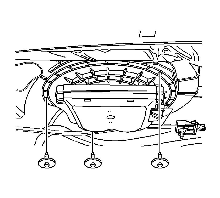
- Disconnect the blower motor electrical connector.
- Remove the blower motor retaining screws.
- Remove the blower motor from the HVAC module.
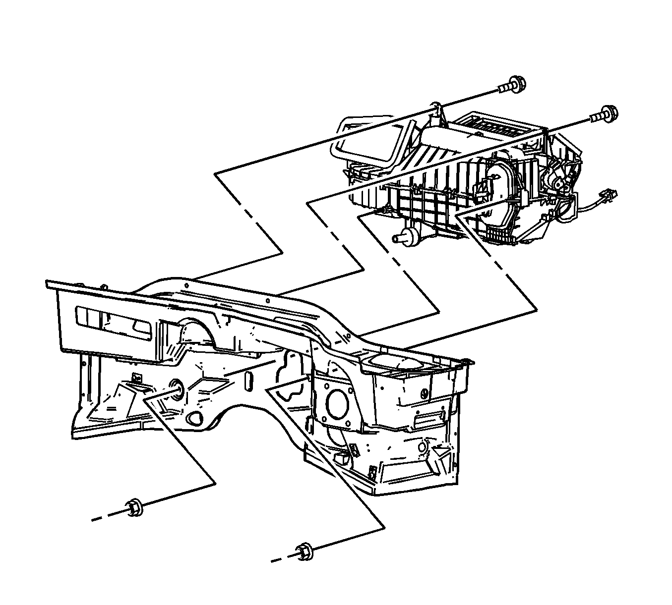
- Remove the retaining and sealing nuts from the cowl.
- Remove the retaining bolts from the upper I/P cross vehicle beam.
- Completely loosen the studs on the HVAC module.
- Loosen the front LH recirculation housing retaining screw.
- Disconnect the recirculation actuator electrical connector.
- Disconnect the HVAC module wiring harness from the recirculation housing.
- Remove the remaining recirculation housing retaining screws.
- Remove the recirculation housing from the HVAC module.
- Reposition the center console wiring harness and the corresponding electrical connectors to the sides of the HVAC module and forward of the lower tie bar.
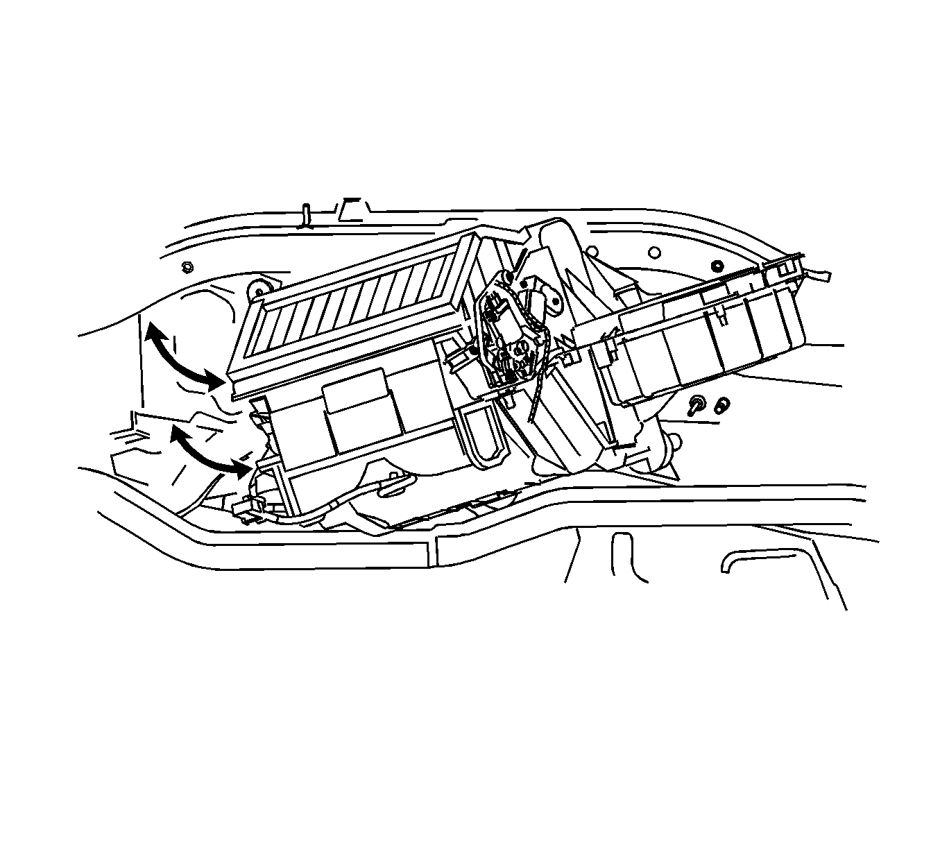
- Carefully remove the HVAC module from the vehicle.
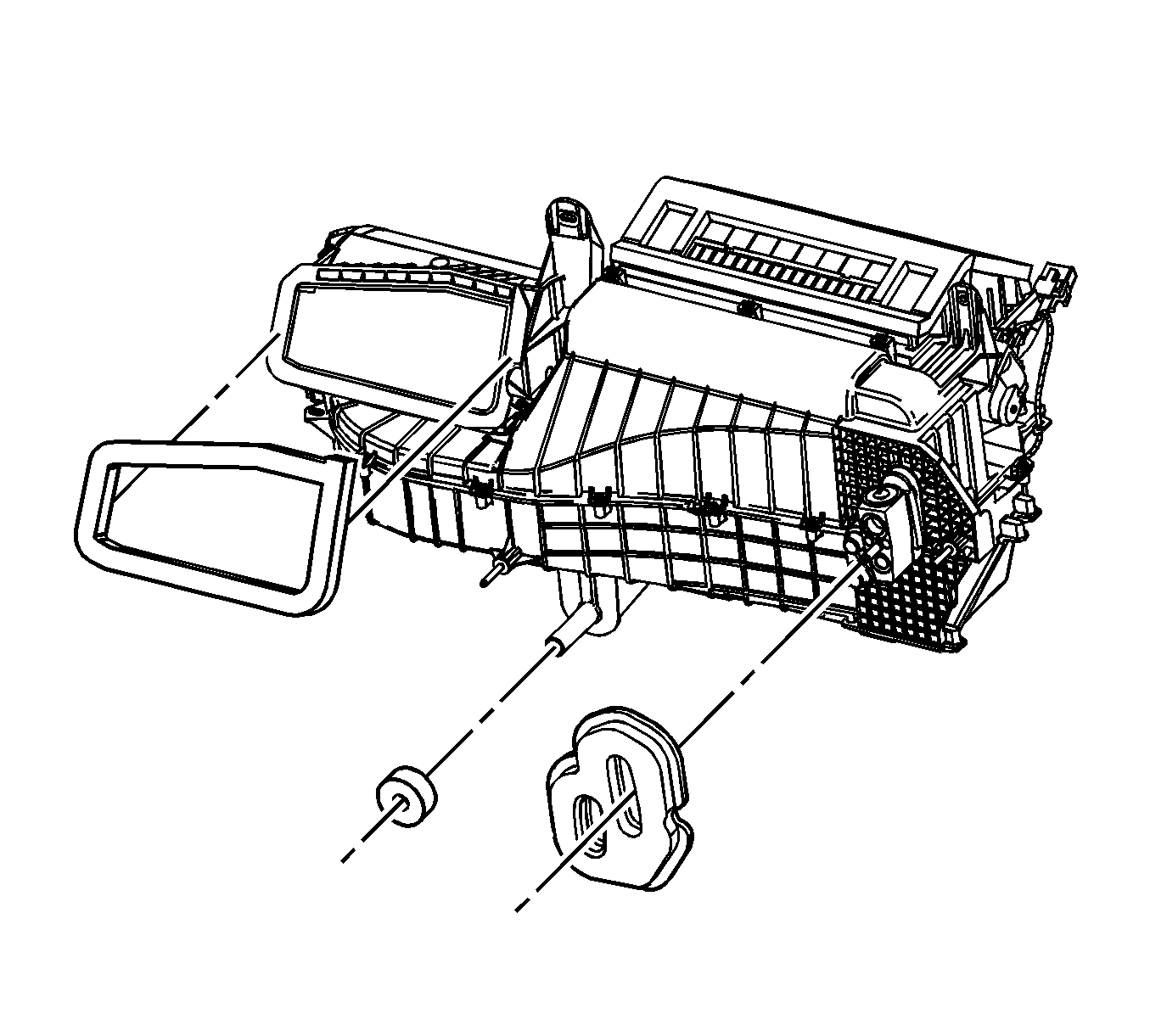
- Remove and discard the air inlet, drain and plumbing seals from the HVAC module.
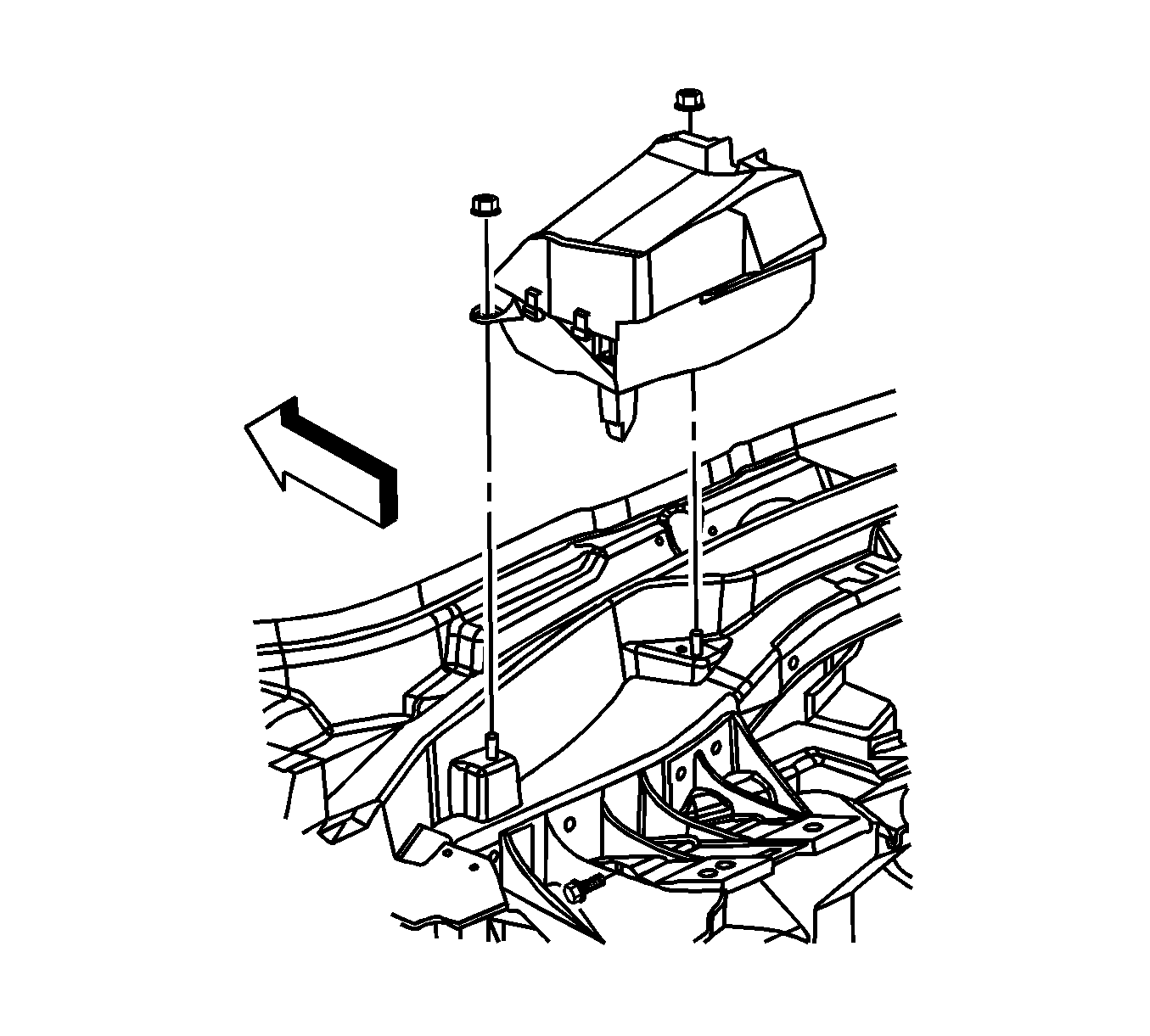
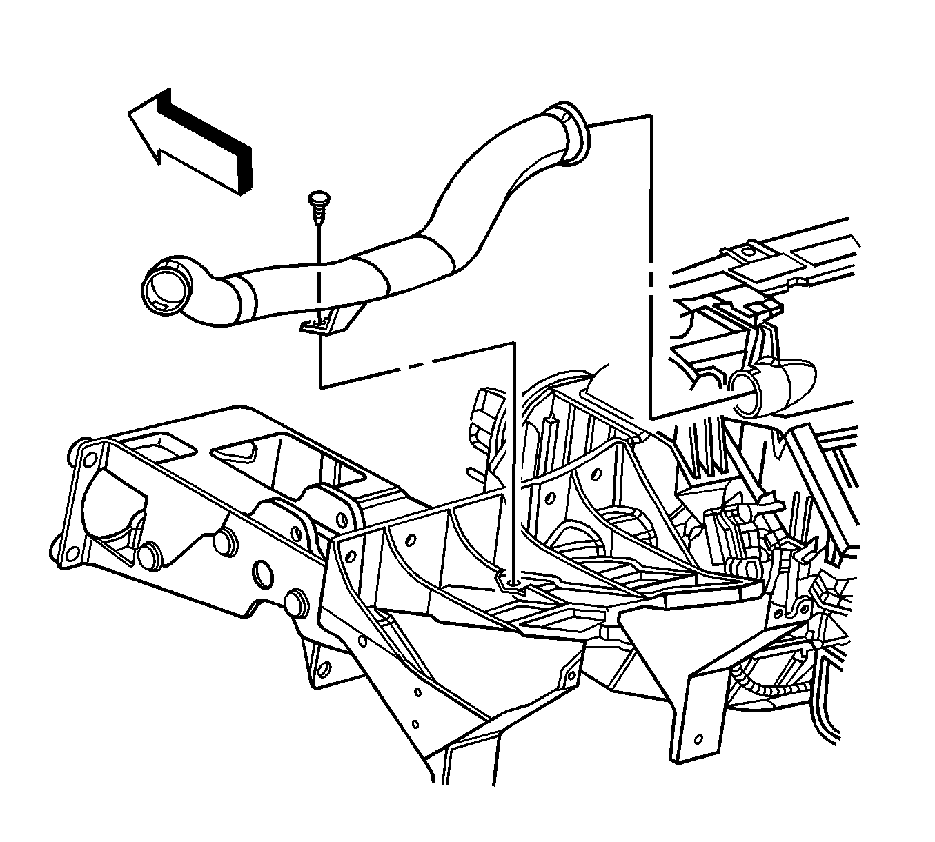
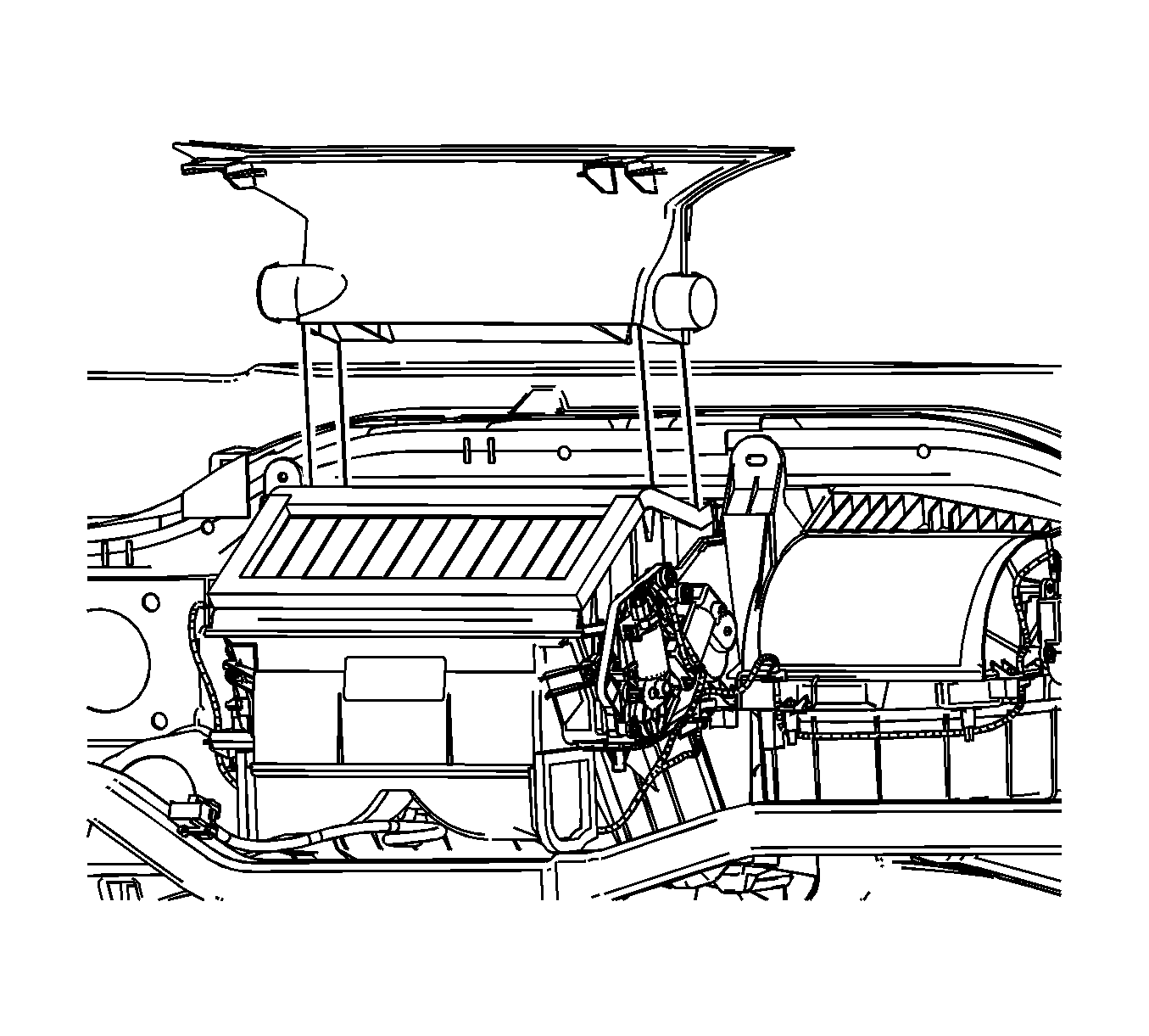
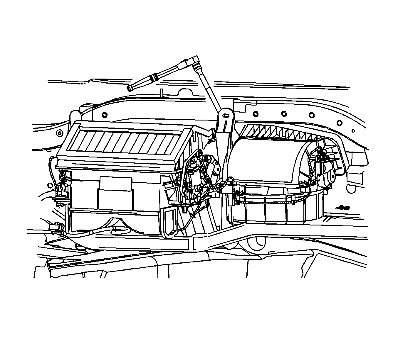
Important: Reposition the HVAC module rearward to access the front left-hand (LH) screw.
The front LH retaining tab of the recirculation housing is slotted.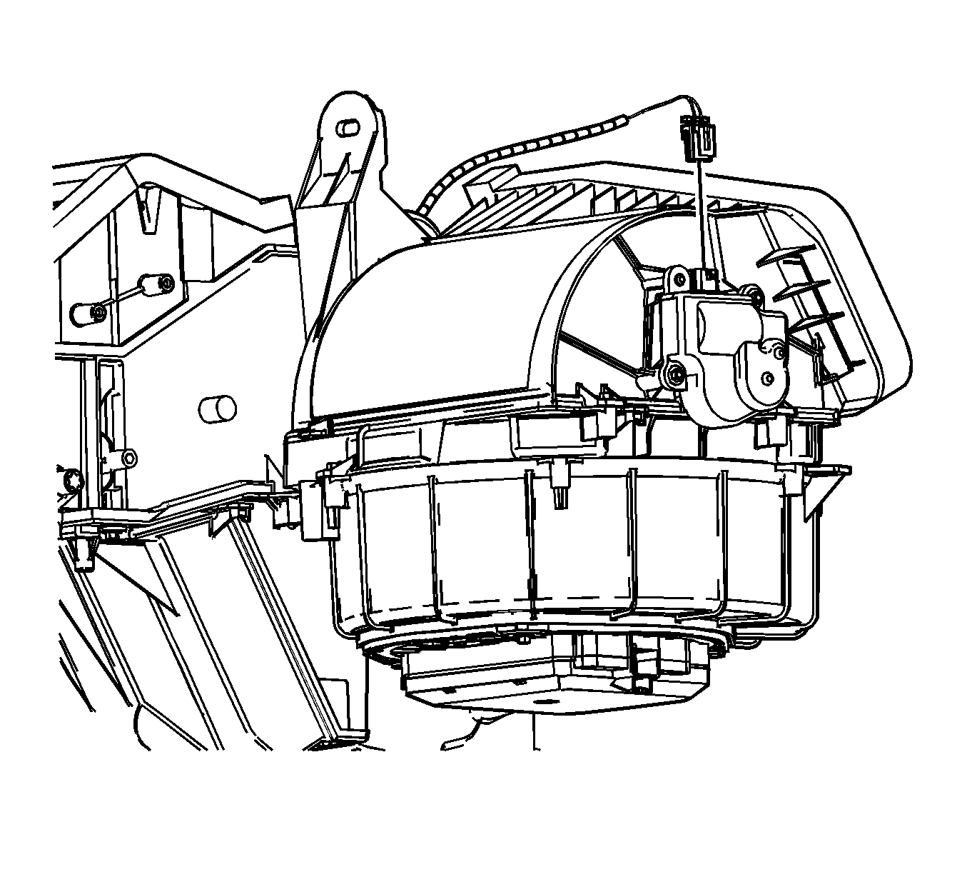
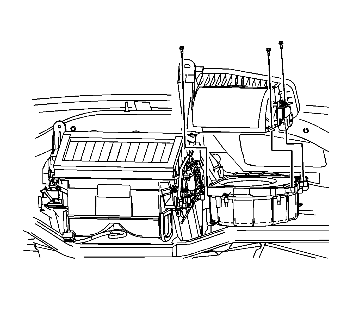
Important: Reposition the center console wiring harness that runs beneath the HVAC module to aide in HVAC module removal.
Installation Procedure
- If a new HVAC module is being installed, add the specified amount of PAG oil to the evaporator core. Refer to Refrigerant System Capacities .
- Install the HVAC module studs.
- Install new air inlet, drain and plumbing seals to the HVAC module.
- Inspect the dash-mat for proper alignment to the cowl. Align if necessary.
- Install the HVAC module into the vehicle.
- Reposition the center console wire harness and the corresponding electrical connectors rearward of the lower tie bar.
- Install the recirculation housing to the HVAC module.
- Install the recirculation housing retaining screws.
- Connect the HVAC module wiring harness to the recirculation housing.
- Connect the recirculation actuator electrical connector.
- Tighten the front LH recirculation housing retaining screw.
- Align the following components to the corresponding openings on the cowl:
- Install the bolts retaining the HVAC module to the upper I/P cross vehicle beam.
- Install new HVAC module retaining and sealing nuts.
- Install the blower motor to the HVAC module.
- Install the blower motor retaining screws.
- Connect the blower motor electrical connector.
- Install the defroster duct to the HVAC module.
- Install the defroster duct retaining screws.
- Install the right floor air outlet duct.
- Install the floor air outlet duct retaining screws.
- Install the lower outlet duct to the side window defogger.
- Connect the lower outlet duct on the side window defogger to the defroster duct.
- Remove the SIR bracket. Refer to Instrument Panel Inflatable Restraint Module Bracket Replacement in Instrument Panel, Gages, and Console.
- Connect the defogger lower outlet duct to the knee bolster bracket.
- Connect the defogger upper outlet duct to the defogger lower outlet duct.
- Install the retainers to the defogger upper outlet duct.
- Install the left rear floor air outlet duct.
- Install the floor air outlet duct retaining screws.
- Connect the window defogger lower outlet duct to the defroster duct.
- Install the defogger lower outlet duct retainer.
- Install the screw that secures the HUD to the steering column bracket.
- Install the HUD retaining nuts.
- Connect the HUD electrical connector.
- Connect the defogger upper outlet duct.
- Install the retainers to the upper defogger duct.
- Install the air distribution duct. Refer to Air Distributor Duct Replacement .
- Install the I/P assembly. Refer to Instrument Panel Assembly Replacement in Instrument Panel, Gages, and Console.
- Install the evaporator drain tube (1) to the HVAC module.
- Install the heater pipe assembly . Refer to Heater Pipes Replacement .
- Fill the cooling system. Refer to Cooling System Draining and Filling in Engine Cooling.
- Evacuate and recharge the A/C system. Refer to Refrigerant Recovery and Recharging .
- Leak test the fittings of the component using J 39400-A .
Notice: Refer to Fastener Notice in the Preface section.
Tighten
Tighten the studs to 4 N·m (35 lb in).

Important: Ensure that the cut-outs on the dash-mat are properly aligned so that the drain and plumbing seals are seated directly against the cowl and the air inlet seal is seated directly against the dash-mat.
The opening in the dash-mat for the HVAC module drain should be aligned so that the drain opening in the cowl is approximately centered in the dash-mat opening; allowing ample room for the module drain seal to fully seat against the cowl.
Notice: Do not force the HVAC module between upper I/P and lower I/P cross vehicle beams. Damage to the HVAC module can result.
Important: Spray a light coat of 3M™ P/N 08877 Silicone Lubricant Plus or equivalent onto the HVAC module heater cover to aid in the installation process.

Tighten
Tighten the screws to 1.6 N·m (14 lb in).


Tighten
Tighten the screw to 1.6 N·m (14 lb in).
Important: If necessary, gently rotate the HVAC module forward to engage the HVAC module studs through the corresponding holes on the cowl.
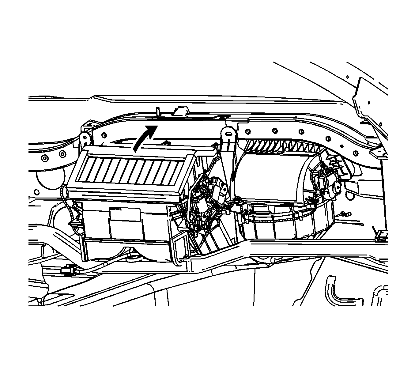
| • | The heater core block fitting |
| • | The evaporator block fitting |
| • | The HVAC module drain |
| • | The HVAC module studs |

Tighten
Tighten the bolts to 5 N·m (44 lb in).
Important: To prevent possible water leaks or wind/road noise from entering the vehicle passenger compartment, do not reuse the old HVAC module retaining and sealing nuts.
Tighten
Tighten the nuts to 10 N·m (89 lb in).

Tighten
Tighten the screws to 1.6 N·m (14 lb in).

Tighten
Tighten the screws to 10 N·m (89 lb in).

Tighten
Tighten the screws to 1.6 N·m (14 lb in).


Tighten
Tighten the screws to 1.6 N·m (14 lb in).

Tighten
Tighten the screw to 3 N·m (27 lb in).
Tighten
Tighten the nuts to 5 N·m (44 lb in).


Important: Ensure that the evaporator drain tube is fully seated to the HVAC module.
