For 1990-2009 cars only
Tools Required
| • | J 26610 Installer |
| • | J 42459 Rack Guide Spring Cap Wrench |
Disassembly Procedure
- Remove the rack and pinion steering assembly from the vehicle. Refer to Steering Gear Replacement .
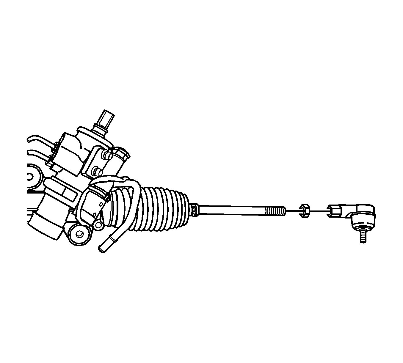
- Mark the threads on the inner tie rod to aid in repositioning the adjusting nut.
- Loosen the adjusting nut and remove the outer tie rod nut and the adjusting nut.
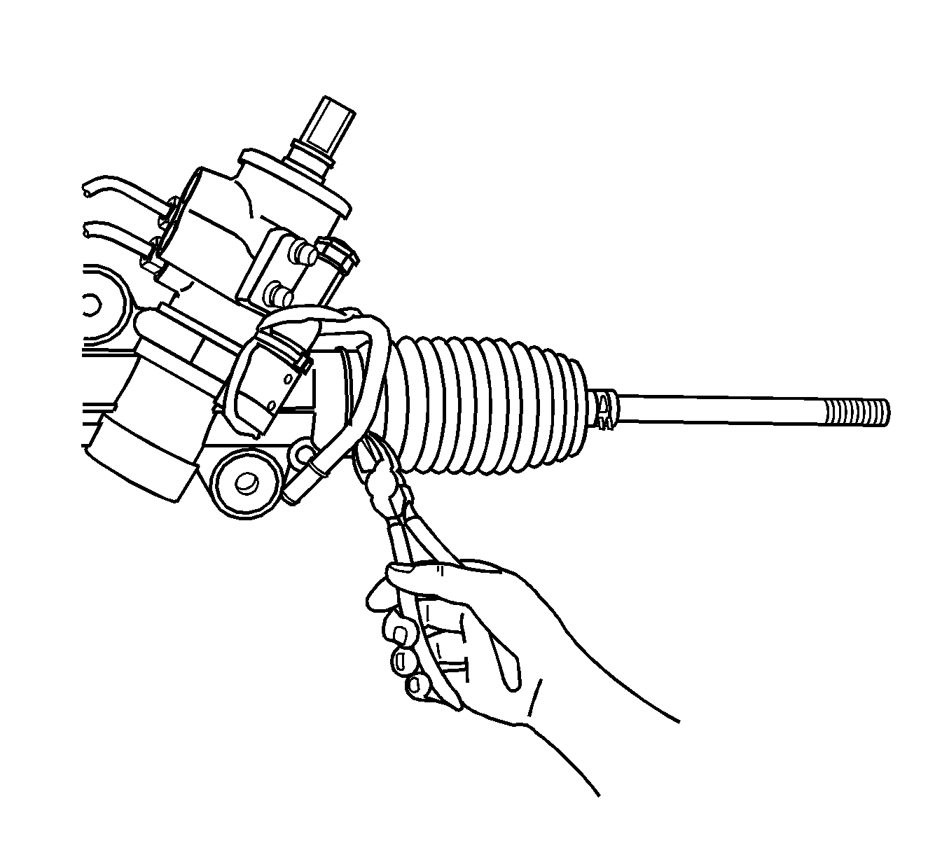
- Remove the dust boot retaining clamps and remove the dust boot.
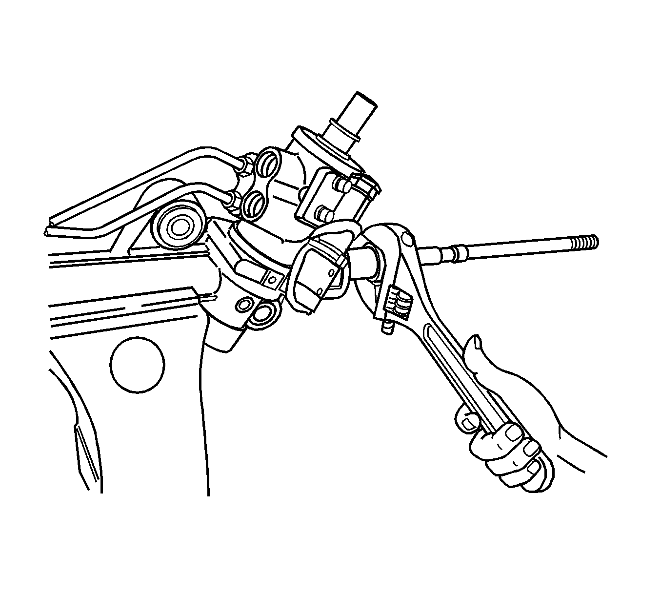
- Remove the inner tie rod.
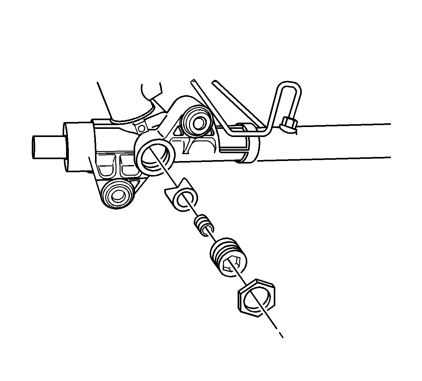
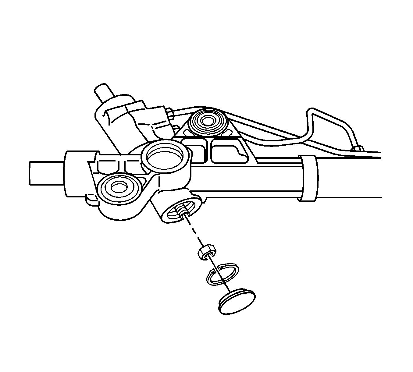
- Remove the adjuster plug lock nut, adjuster plug, adjuster spring, and rack bearing.
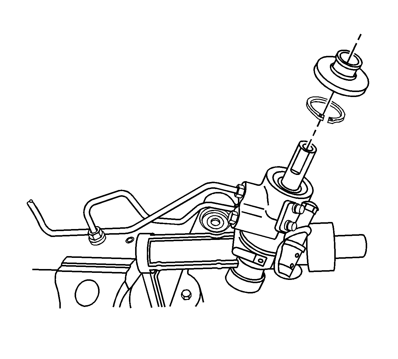
- Remove the dust cover, snap ring, and pinion lock nut. The pinion lock nut can be removed when the pinion shaft is fixed.
- Remove the rubber dust cover and snap ring.
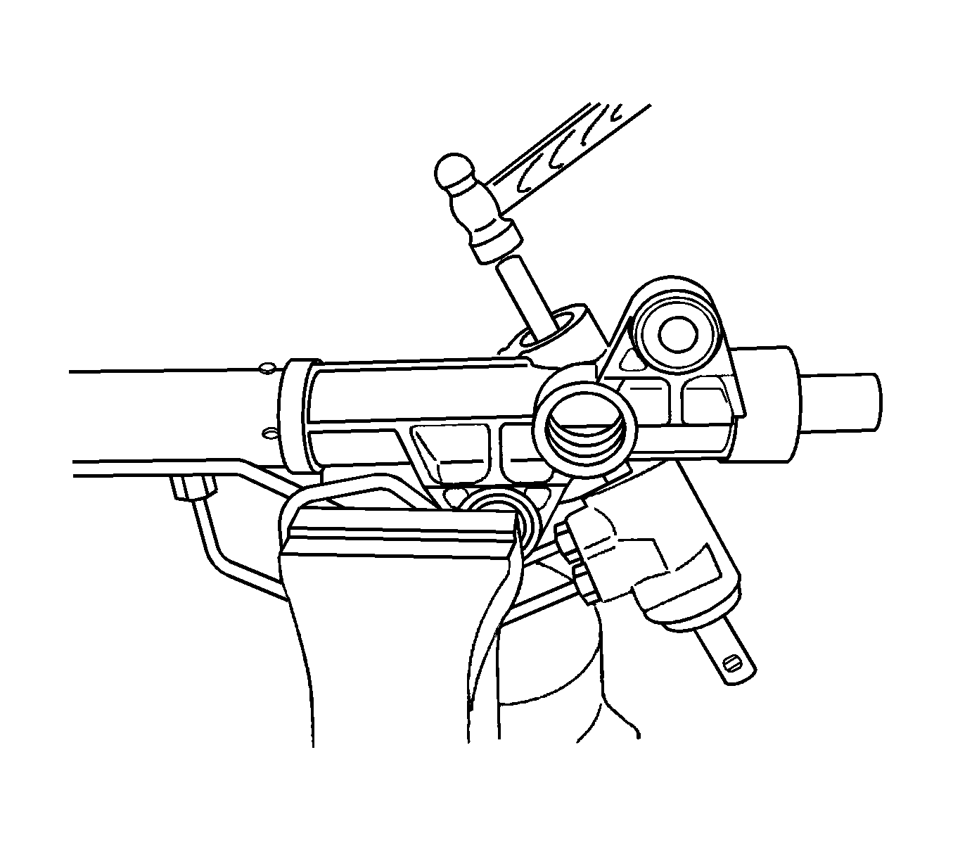
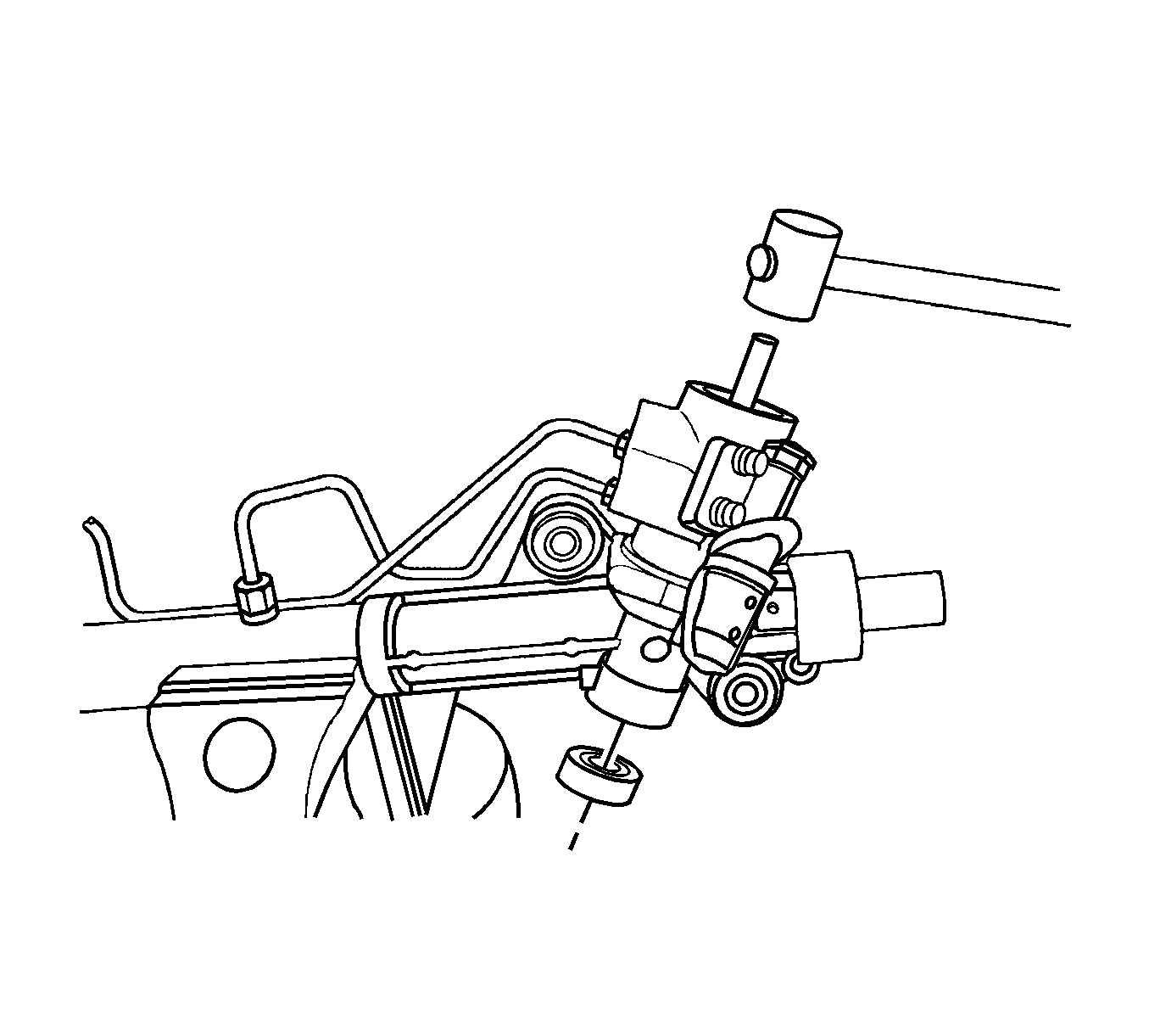
- Remove the gear and valve assembly by tapping on the pinion shaft gently with a hammer and steel bar.
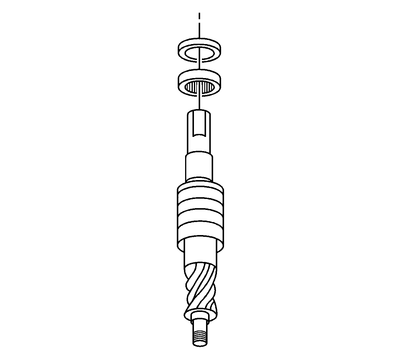
- Remove the pinion shaft seal and middle bearing.
- Remove the pinion shaft ball bearing by tapping on the pinion shaft gently with a rubber hammer and steel bar.
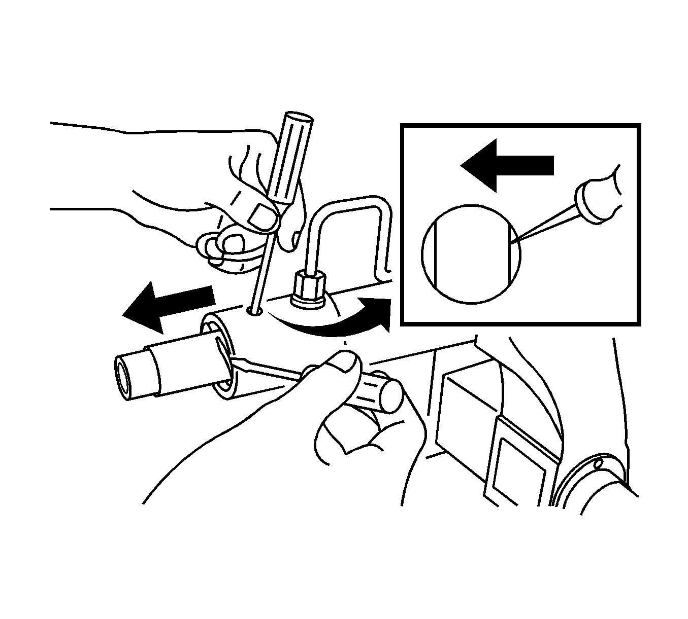
- To remove the steering rack gear, remove the circlip from the rack gear housing.
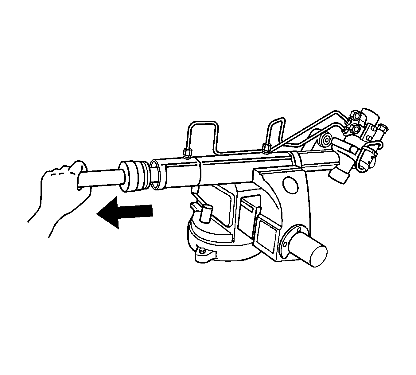
- Pull out the rack gear and rack gear stopper at the same time from the rack gear housing.
Assembly Procedure
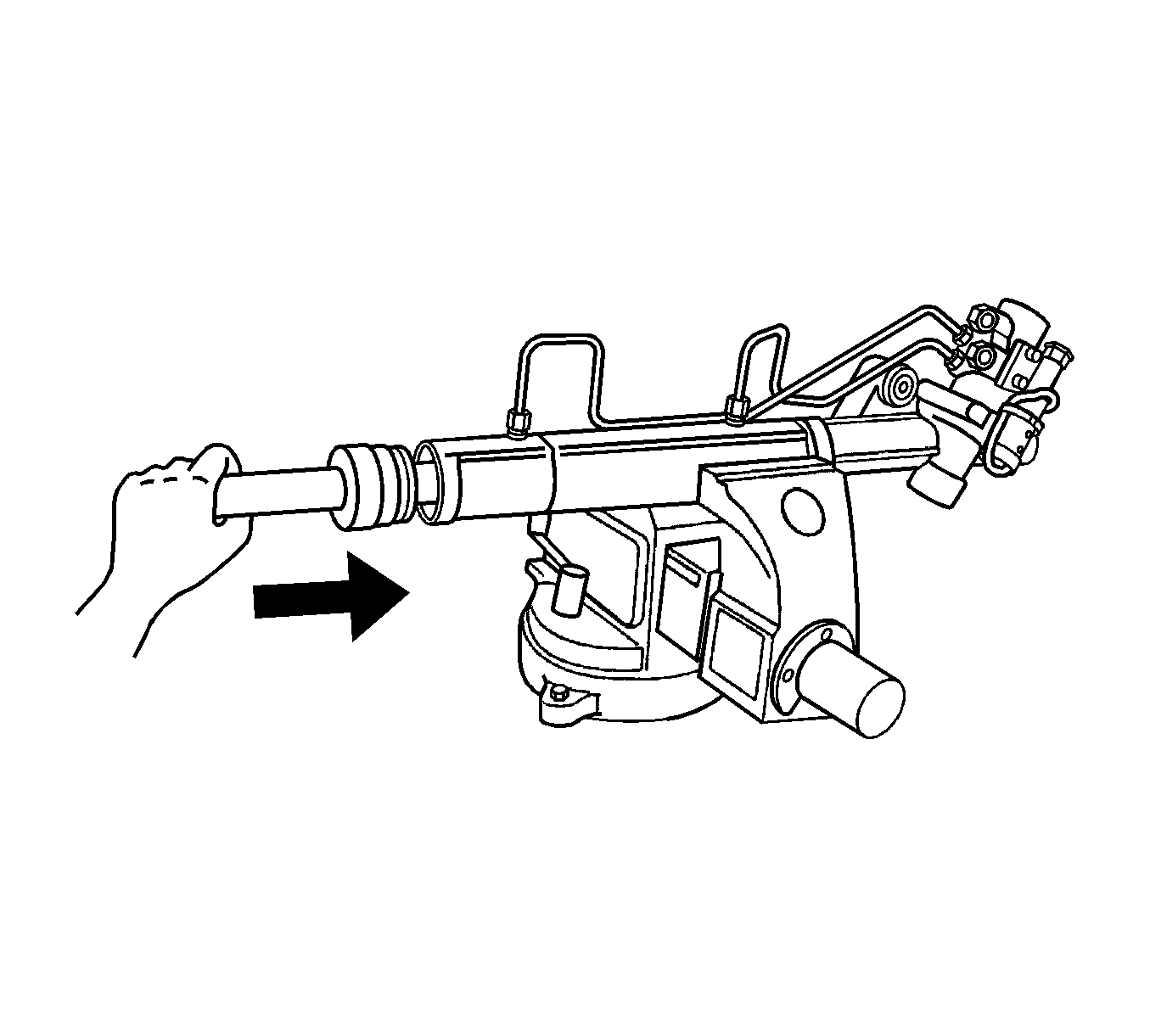
- Install the rack gear and rack gear stopper to the rack gear housing.
- Install the circlip.
- Install the pinion shaft ball bearing.
- Install the pinion shaft, seal and needle bearing.
- Install the snap ring and the rubber dust cover.
- Install the pinion lock nut.
- Coat the rack bearing, the adjuster spring, and the adjuster plug with lithium-based grease and install them into the housing.
- With the rack centered, turn the adjuster plug clockwise.
- Inspect the pinion torque.
- Thread the locknut on the adjuster plug and tighten it.
- Install the tie rod.
- Install the dust boot and retaining clamps with J 26610 .
- Install the outer tie rod and lock nut.
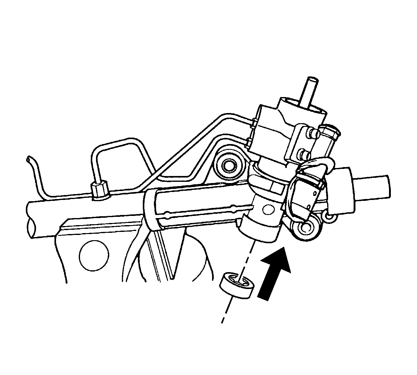


Notice: Refer to Fastener Notice in the Preface section.

Tighten
Tighten the pinion lock nut to 30 N·m (22 lb ft).

Specification
Turn the adjuster plug clockwise until a torque of 7 N·m (62 lb in) is obtained, then back it off by 30-40 degrees.
Specification
Maximum pinion preloaded torque is 1 N·m (9 lb in).
Tighten
Tighten the adjuster plug locknut to 75 N·m (55 lb ft) while holding the adjuster plug stationary with the
J 42459
or with a 19 mm allen
wrench.

Tighten
Tighten the inner tie rod to 100 N·m (74 lb ft).
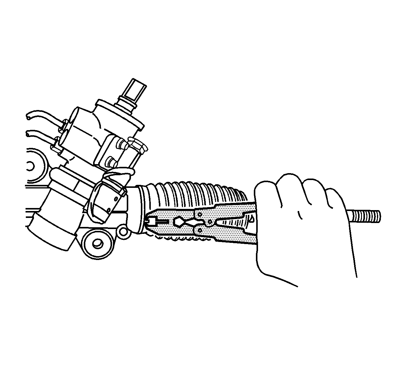

Tighten
Tighten the outer tie rod end lock nut to 64 N·m (47 lb ft).
