Air Conditioning Evaporator Core Replacement First Design
Removal Procedure
The first design can be identified by the attachment method of the evaporator outlet hose and the liquid line to the thermal expansion valve (TXV) . They are retained to the TXV independently using nuts.
- Remove the HVAC module. Refer to HVAC Module Assembly Replacement .
- Remove the evaporator case assembly. Refer to Air Conditioning (A/C) Evaporator Case Assembly Replacement .
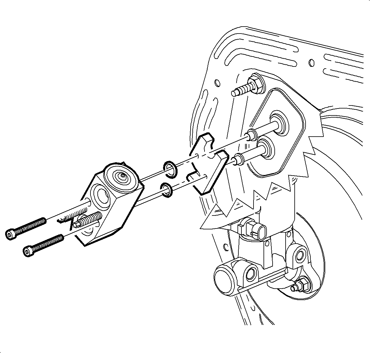
- Remove the TXV bolts from the backing plate.
- Remove the TXV and the backing plate from the evaporator pipes.
- Remove the O-rings from evaporator pipes. Refer to O-Ring Replacement .
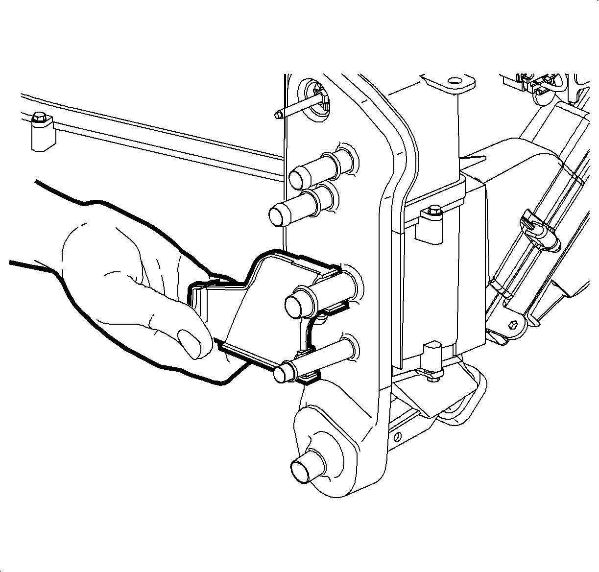
- Install protective caps to the evaporator pipes to prevent system contamination.
- Remove the HVAC module front of dash seal.
- Remove the evaporator pipe cover screw from the blower case assembly.
- Remove the evaporator pipe cover from the blower case assembly.
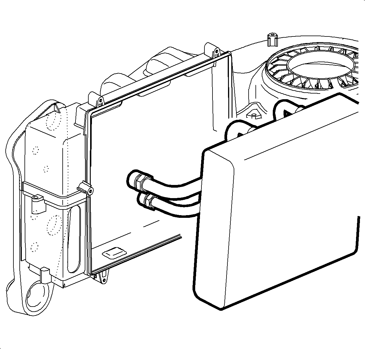
- Remove the evaporator core from the blower case assembly. Spraying the perimeter of the evaporator core seal with a soap and water mixture will ease removal.
Installation Procedure
- Add the proper of polyalkylene glycol (PAG) oil to the evaporator core. Refer to Refrigerant System Capacities .
- Inspect the seal around the evaporator core. Make sure the seal is in correct position and retained properly.
- Spray the seal with a soap and water mixture to ease the installation of evaporator core.
- Install the evaporator core to the blower case assembly.
- Install the evaporator pipe cover.
- Install the evaporator pipe cover screw.
- Install the HVAC module front of dash seal.
- Remove the protective caps from the evaporator pipes and ensure the seal areas are clean, dry and lint-free.
- Install new O-rings to the evaporator pipes. Refer to O-Ring Replacement .
- Instal the TXV and the backing plate to the evaporator pipes.
- Install the TXV screws to the backing plate.
- Install the evaporator case assembly. Refer to Air Conditioning (A/C) Evaporator Case Assembly Replacement .
- Install the HVAC module. Refer to HVAC Module Assembly Replacement .


Notice: Use the correct fastener in the correct location. Replacement fasteners must be the correct part number for that application. Fasteners requiring replacement or fasteners requiring the use of thread locking compound or sealant are identified in the service procedure. Do not use paints, lubricants, or corrosion inhibitors on fasteners or fastener joint surfaces unless specified. These coatings affect fastener torque and joint clamping force and may damage the fastener. Use the correct tightening sequence and specifications when installing fasteners in order to avoid damage to parts and systems.
Tighten
Tighten the screw to 1 N·m (9 lb in).

Important: Use only R-12 refrigerant oil (mineral) to lubricate O-rings. Use of R-134a PAG oil will cause premature corrosion of fitting joints.
Use only clean lint free cloths with non-petroleum based solvents to clean refrigerant system sealing surfaces. Allow solvent to dry with air. Do not allow solvents to enter refrigerant system.Tighten
Tighten the screws to 9 N·m (80 lb in).
Air Conditioning Evaporator Core Replacement Second Design
Removal Procedure
The second design can be identified by the attachment method of the evaporator outlet hose and the liquid line to the Thermal Expansion Valve (TXV) . They are retained to the TXV as a pair using a single nut.
- Remove the HVAC module. Refer to HVAC Module Assembly Replacement .
- Remove the evaporator case assembly. Refer to Air Conditioning (A/C) Evaporator Case Assembly Replacement .
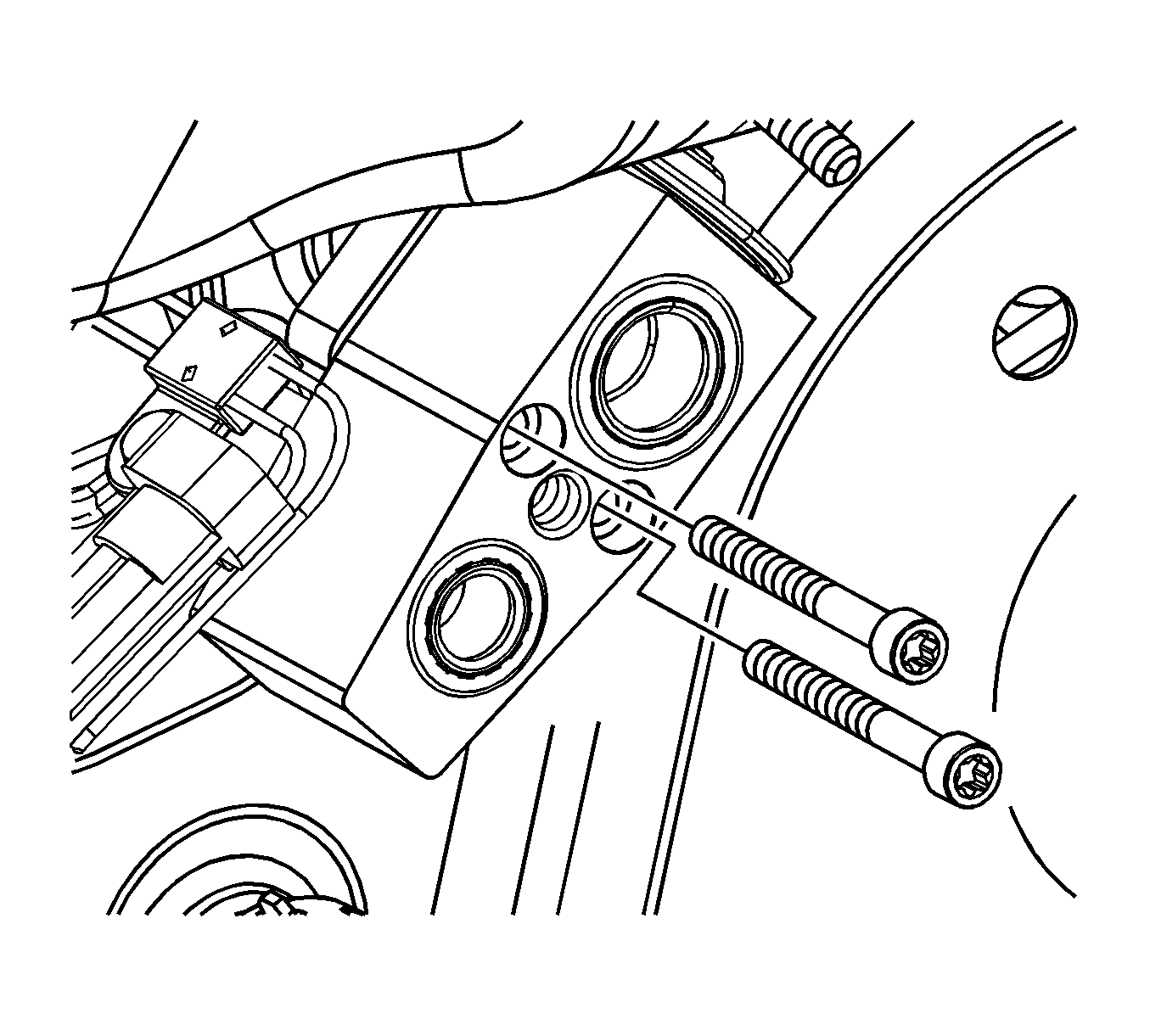
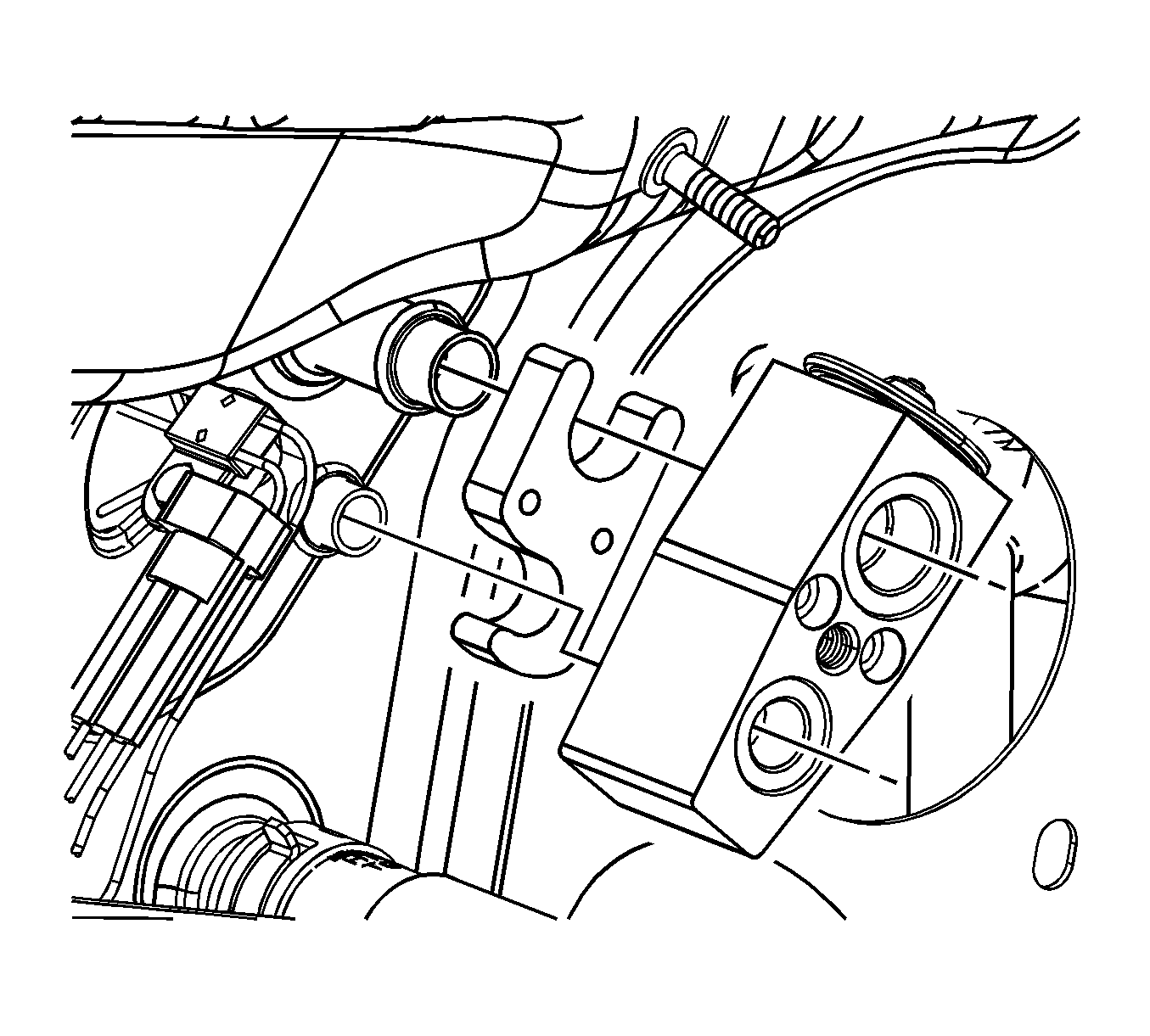
- Remove the thermal expansion valve (TXV) bolts from the backing plate.
- Remove the TXV and the backing plate from the evaporator pipes.
- Remove the O-rings from evaporator pipes. Refer to O-Ring Replacement .
- Install protective caps to the evaporator pipes to prevent system contamination.
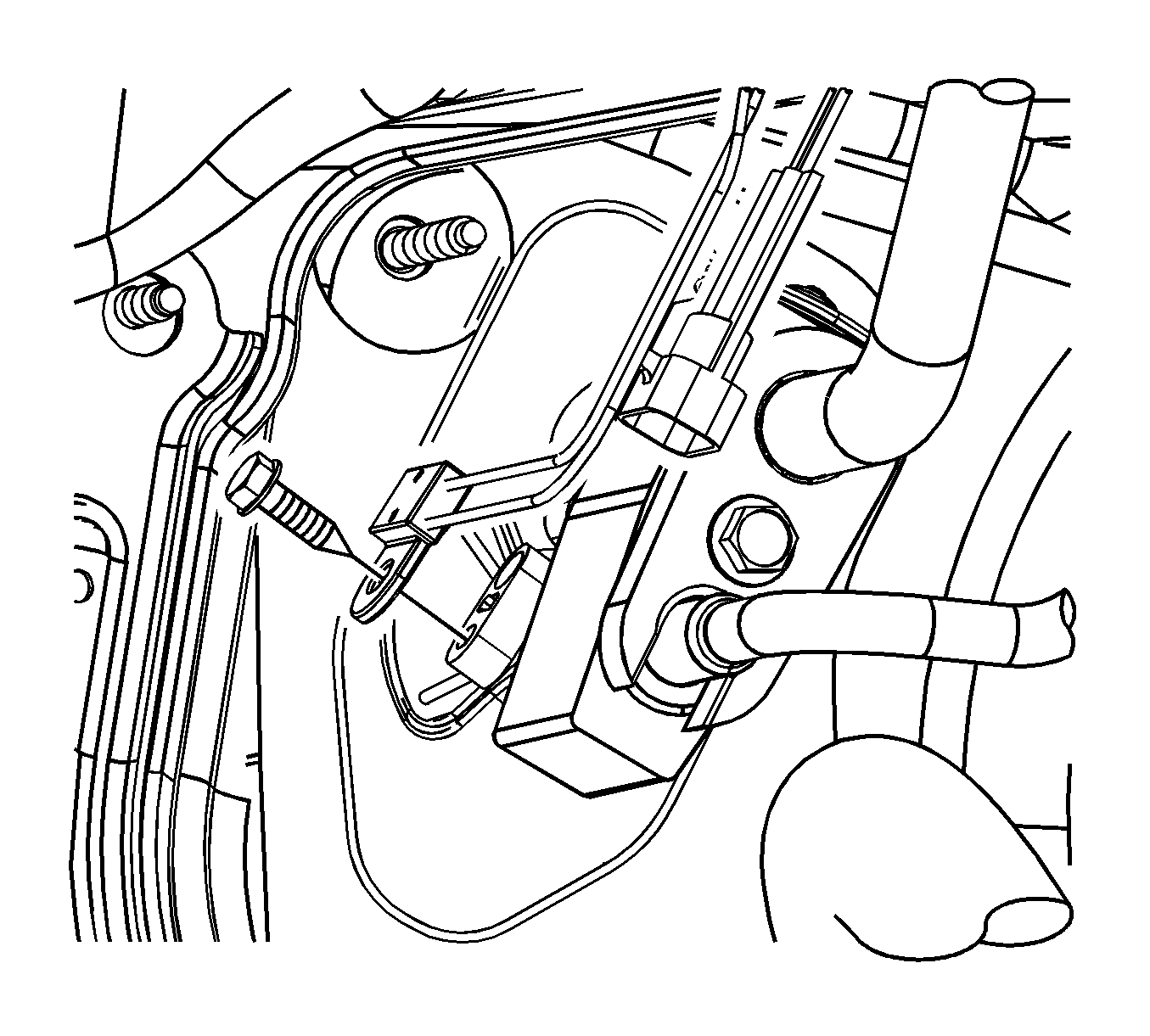
- Disconnect the thermal expansion valve (TXV) temperature sensor from the engine harness.
- Remove the temperature sensor screw from the evaporator pipe.
- Remove the temperature sensor from the evaporator pipe.
- Remove the HVAC module front of dash seal.
- Remove the evaporator pipe cover screw from the blower case assembly.
- Remove the evaporator pipe cover from the blower case assembly.
- Remove the evaporator core from the blower case assembly. Spraying the perimeter of the evaporator core seal with a soap and water mixture will ease removal.


Installation Procedure
- Add the proper of polyalkylene glycol (PAG) oil to the evaporator core. Refer to Refrigerant System Capacities .
- Inspect the seal around the evaporator core. Make sure the seal is in correct position and retained properly.
- Spray the seal with a soap and water mixture to ease the installation of evaporator core.
- Install the evaporator core to the blower case assembly.
- Install the evaporator pipe cover.
- Install the evaporator pipe cover screw.
- Install the HVAC module front of dash seal.
- Fill the temperature sensor housing in the TXV with the thermal grease included with the service kit.
- Install the temperature sensor and wipe away the excess grease.
- Install the temperature sensor screw.
- Connect the temperature sensor to the engine harness.
- Remove the protective caps from the evaporator pipes and ensure the seal areas are clean, dry and lint free.
- Install new O-rings to the evaporator pipes. Refer to O-Ring Replacement .
- Instal the TXV and the backing plate to the evaporator pipes.
- Install the TXV screws to the backing plate.
- Install the evaporator case assembly. Refer to Air Conditioning (A/C) Evaporator Case Assembly Replacement .
- Install the HVAC module. Refer to HVAC Module Assembly Replacement .


Notice: Use the correct fastener in the correct location. Replacement fasteners must be the correct part number for that application. Fasteners requiring replacement or fasteners requiring the use of thread locking compound or sealant are identified in the service procedure. Do not use paints, lubricants, or corrosion inhibitors on fasteners or fastener joint surfaces unless specified. These coatings affect fastener torque and joint clamping force and may damage the fastener. Use the correct tightening sequence and specifications when installing fasteners in order to avoid damage to parts and systems.
Tighten
Tighten the screw to 1 N·m (9 lb in).

Important: The TXV cavity for temperature sensor must be packed with thermal grease to ensure functionality.
Tighten
Tighten the screw to 8.5 N·m (75 lb in).

Important: Use only R-12 refrigerant oil (mineral) to lubricate O-rings. Use of R-134a PAG oil will cause premature corrosion of fitting joints.
Use only clean lint free cloths with non-petroleum based solvents to clean refrigerant system sealing surfaces. Allow solvent to dry with air. Do not allow solvents to enter refrigerant system.
Tighten
Tighten the screws to 8 N·m (71 lb in).
