Removal Procedure
- Drain the cooling system. Refer to Cooling System Draining and Filling.
- Remove the upper intake manifold. Refer to Fuel Injector Sight Shield Replacement.
- Remove the heater inlet pipe. Refer to Heater Inlet Pipe Replacement.
- Disconnect the radiator inlet hose from the thermostat housing. Refer to Radiator Inlet Hose Replacement.
- Remove the fuel rail assembly. Refer to Fuel Injection Fuel Rail Assembly Replacement.
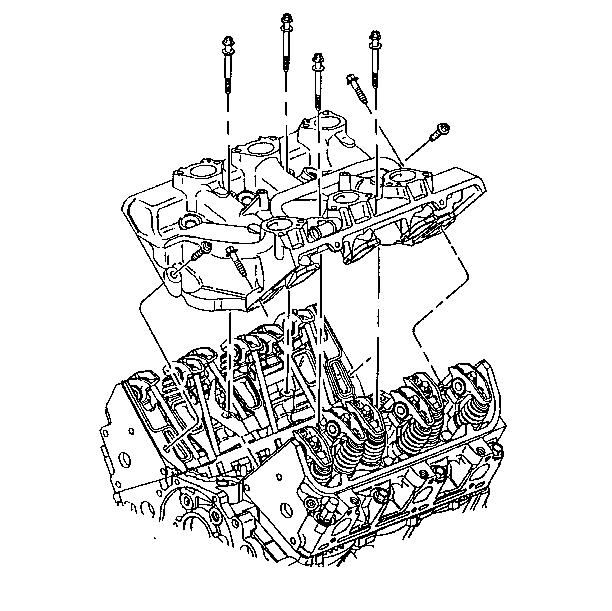
- Remove the lower intake manifold bolts.
- Remove the lower intake manifold from the engine.
- If replacing the lower intake manifold, remove the thermostat and housing. Refer to Engine Coolant Thermostat Replacement.
- Remove the rocker arms and push rods. Refer to Valve Rocker Arm and Push Rod Replacement.
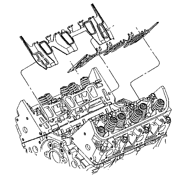
- Remove the lower intake manifold gaskets.


Installation Procedure
- Install the lower intake manifold gaskets.
- Install the rocker arms and push rods. Refer to Valve Rocker Arm and Push Rod Replacement.
- Install the lower intake manifold seals.
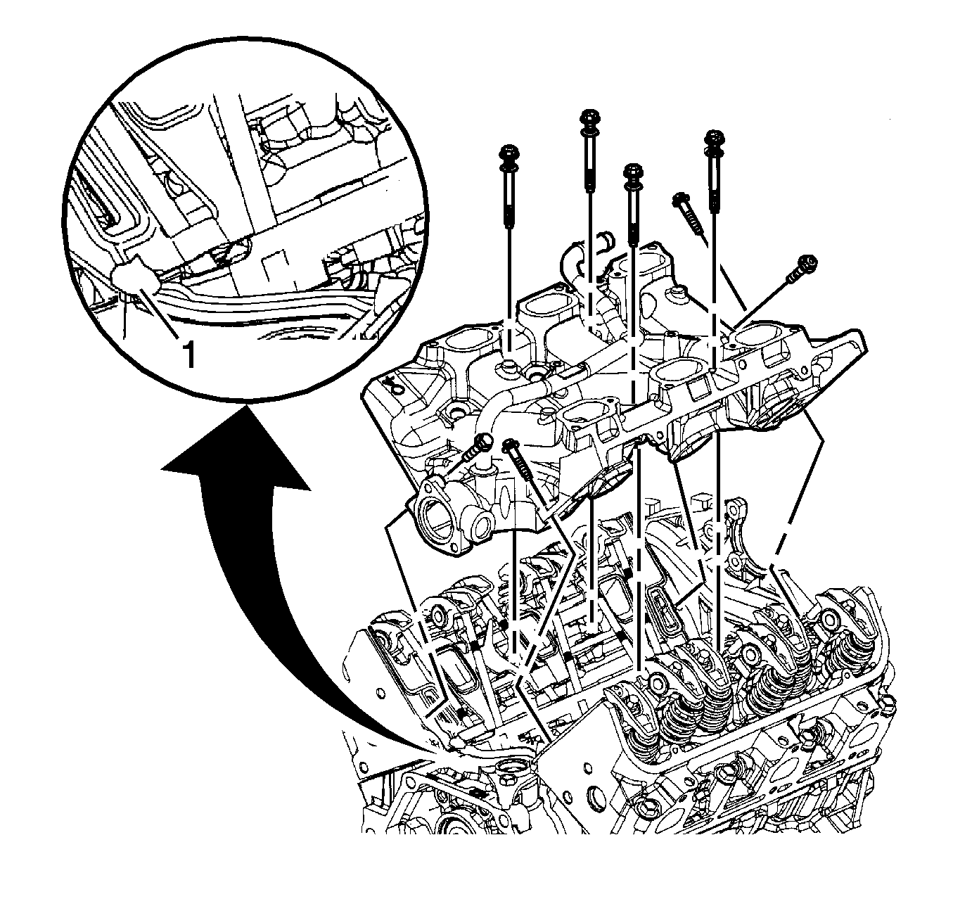
- With the seals in place, apply a small drop 8-10 mm (0.31-0.39 in) of RTV sealer (1). Refer to Adhesives, Fluids, Lubricants, and Sealers for the correct part number.
- Install the lower intake manifold to the engine.
- Install the lower intake manifold bolts.
- Install the fuel rail assembly. Refer to Fuel Injection Fuel Rail Assembly Replacement.
- Connect the radiator inlet hose to the thermostat housing. Refer to Radiator Inlet Hose Replacement.
- Install the heater inlet pipe. Refer to Heater Inlet Pipe Replacement.
- Install the upper intake manifold. Refer to Fuel Injector Sight Shield Replacement.
- Fill the cooling system. Refer to Cooling System Draining and Filling.

Note:
• All gasket mating surfaces must remain free of oil and foreign material. Refer to
Adhesives, Fluids, Lubricants, and Sealers for the correct part number to use to clean surfaces. • Do not apply room temperature vulcanizing (RTV) sealer to the engine block prior to the installation of the manifold gaskets. RTV sealer is not to be placed under the lower intake manifold gaskets.

Caution: Refer to Fastener Caution in the Preface section.

Caution: Maximum gasket performance is achieved when using new fasteners, which contain a thread-locking patch. If the fasteners are not replaced, a thread locking chemical must be applied to the fastener threads. Failure to replace the fasteners or apply a thread-locking chemical MAY reduce gasket sealing capability.
Note:
• All lower intake manifold bolts need to be clean, free of foreign materials, and reused only if new bolts are unavailable. Refer to
Adhesives, Fluids, Lubricants, and Sealers for the correct part number. Apply
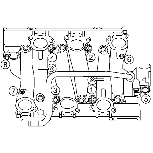
to the old intake manifold bolt threads. • Manufacturer recommends the center bolts be fully torqued before the diagonal bolts to assure proper torque distribution. • Lower intake manifold bolts in locations (6) and (7) should be torqued to specification using a crows foot type tool.
| • | Tighten the lower intake manifold bolts in sequence to 13 N·m (115 lb in) on the first pass. |
| • | Tighten the lower intake manifold bolts (1, 2, 3, 4) in sequence to 20 N·m (15 lb ft) on the final pass. |
| • | Tighten the lower intake manifold bolts (5, 6, 7, 8) in sequence to 25 N·m (18 lb ft) on the final pass. |
