Instrument Panel Upper Trim Pad Replacement Impala
Removal Procedure
- Remove the instrument panel (IP) cluster trim plate. Refer to Instrument Panel Cluster Trim Plate Bezel Replacement .
- Remove the garnish moldings from the left and the right windshield pillar. Refer to Windshield Pillar Garnish Molding Replacement in Interior Trim.
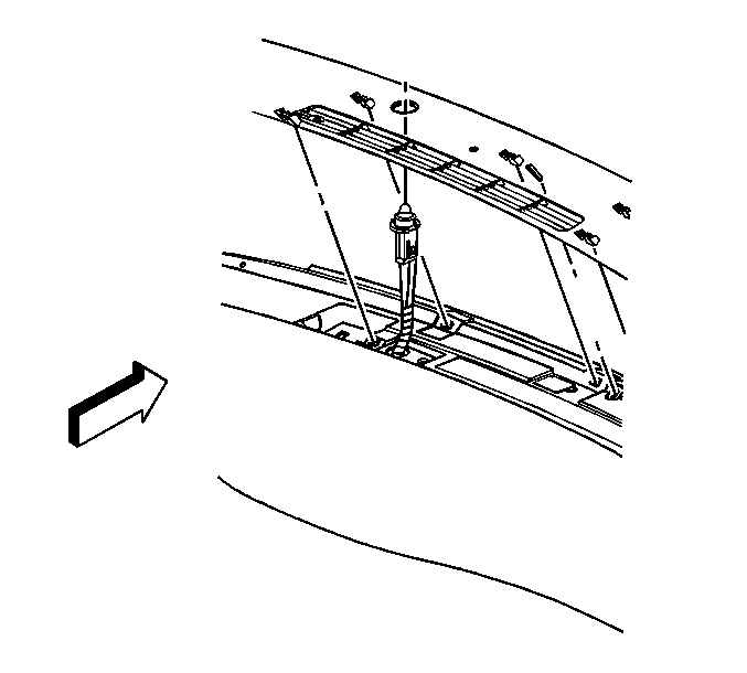
- Starting at the right side, carefully lift upwards on the defroster grille in order to release the retainers. Continue working to the left side until all of the retainers are released.
- Disconnect the daytime running lamps (DRL) sensor from the defroster grille.
- Remove the defroster grille.
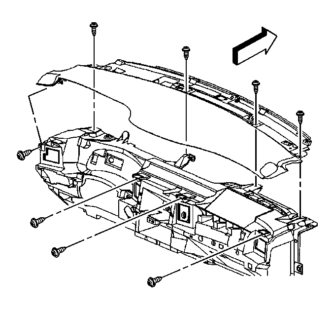
- Remove the screws from the IP upper trim pad.
- Remove the remote keyless entry module. Refer to Remote Control Door Lock Receiver Replacement in Keyless Entry.
- Remove the upper trim pad from the IP.
Caution: When you are performing service on or near the SIR components or the SIR wiring, you must disable the SIR system. Refer to Disabling the SIR System. Failure to follow the correct procedure could cause air bag deployment, personal injury, or unnecessary SIR system repairs.


Installation Procedure
- Position the upper trim pad to the IP.
- Install the IP upper trim pad screws.
- Position the defroster grille to the upper IP. Connect the DRL sensor to the defroster grille. Ensure that the DRL sensor wiring harness will not be pinched when the defroster grille is installed.
- Starting at the left side, install the defroster grille retainers into the upper IP. Continue working to the right side until you have installed all of the retainers.
- Install the garnish moldings to the right and the left windshield pillar. Refer to Windshield Pillar Garnish Molding Replacement in Interior Trim.
- Install the IP cluster trim plate. Refer to Instrument Panel Cluster Trim Plate Bezel Replacement .

Install the remote keyless entry module. Refer to Remote Control Door Lock Receiver Replacement in Keyless Entry.
Notice: Use the correct fastener in the correct location. Replacement fasteners must be the correct part number for that application. Fasteners requiring replacement or fasteners requiring the use of thread locking compound or sealant are identified in the service procedure. Do not use paints, lubricants, or corrosion inhibitors on fasteners or fastener joint surfaces unless specified. These coatings affect fastener torque and joint clamping force and may damage the fastener. Use the correct tightening sequence and specifications when installing fasteners in order to avoid damage to parts and systems.
Tighten
| • | Tighten the horizontal screws to 2 N·m (18 lb in). |
| • | Tighten the vertical screws to 10 N·m (89 lb in). |

Instrument Panel Upper Trim Pad Replacement Monte Carlo
Removal Procedure
- Remove the instrument panel (IP) cluster trim plate. Refer to Instrument Panel Cluster Trim Plate Bezel Replacement .
- Remove the IP right upper trim panel. Refer to Instrument Panel Trim Panel Replacement - Right Side .
- Remove the garnish moldings from the left and the right windshield pillar. Refer to Windshield Pillar Garnish Molding Replacement in Interior Trim.
- Starting at the right side, carefully lift upwards on the defroster grille in order to release the retainers. Continue working to the left side until you have released all of the retainers.
- Disconnect the daytime running lamps (DRL) sensor from the defroster grille.
- Remove the defroster grille.
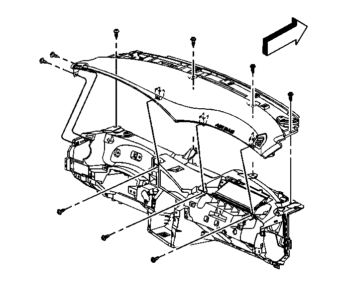
- Remove the IP upper trim pad screws.
- Remove the remote keyless entry module. Refer to Remote Control Door Lock Receiver Replacement in Keyless Entry.
- Remove the IP upper trim pad.

Caution: When you are performing service on or near the SIR components or the SIR wiring, you must disable the SIR system. Refer to Disabling the SIR System. Failure to follow the correct procedure could cause air bag deployment, personal injury, or unnecessary SIR system repairs.
Installation Procedure
- Position the IP upper trim pad to the IP.
- Install the IP upper trim pad screws.
- Position the defroster grille to the upper IP. Connect the DRL sensor to the defroster grille. Ensure that the DRL sensor wiring harness is not be pinched when you install the defroster grille.
- Starting at the left side, install the defroster grille retainers into the upper IP. Continue working to the right side until all of the retainers are installed.
- Install the garnish moldings to the right and the left windshield pillar. Refer to Windshield Pillar Garnish Molding Replacement in Interior Trim.
- Install the IP right upper trim panel. Refer to Instrument Panel Trim Panel Replacement - Right Side .
- Install the IP cluster trim plate. Refer to Instrument Panel Cluster Trim Plate Bezel Replacement .

Install the remote keyless entry module. Refer to Remote Control Door Lock Receiver Replacement in Keyless Entry.
Notice: Use the correct fastener in the correct location. Replacement fasteners must be the correct part number for that application. Fasteners requiring replacement or fasteners requiring the use of thread locking compound or sealant are identified in the service procedure. Do not use paints, lubricants, or corrosion inhibitors on fasteners or fastener joint surfaces unless specified. These coatings affect fastener torque and joint clamping force and may damage the fastener. Use the correct tightening sequence and specifications when installing fasteners in order to avoid damage to parts and systems.
Tighten
| • | Tighten the horizontal screws to 2 N·m (18 lb in). |
| • | Tighten the vertical screws to 10 N·m (89 lb in). |
