Front Disc Brake Pads Replacement TRW - Pin Slider
Caution: Refer to Brake Dust Caution in the Preface section.
Removal Procedure
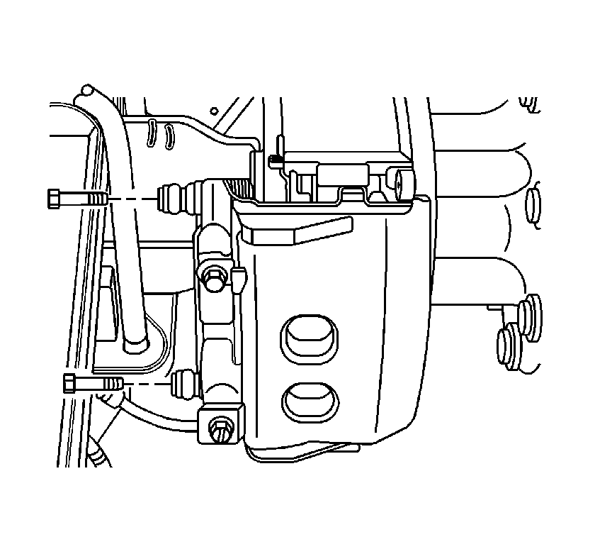
- Remove the brake caliper. Refer to Front Brake Caliper Replacement .
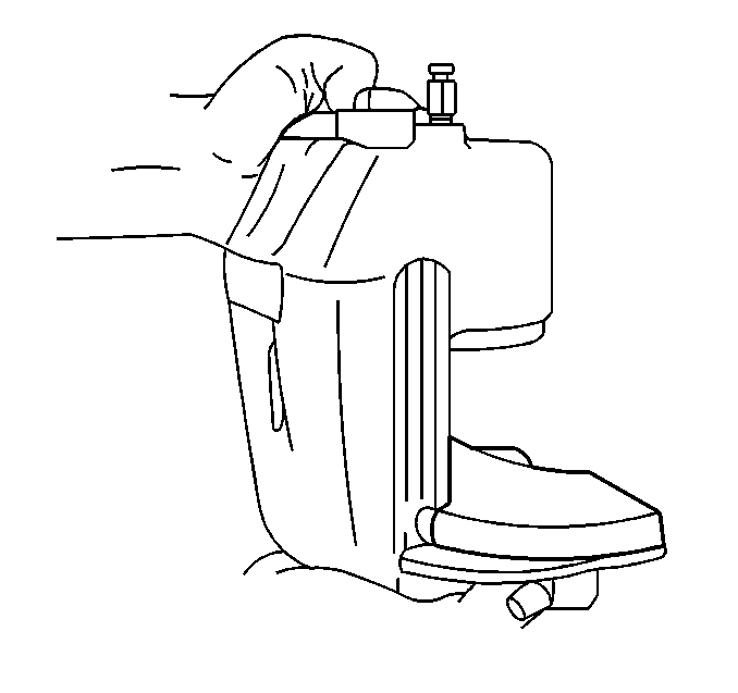
- Remove the inner brake pad from the brake caliper mounting plate.
- Remove the outer brake pad.

Notice: Support the brake caliper with heavy mechanic wire, or equivalent, whenever it is separated from its mount and the hydraulic flexible brake hose is still connected. Failure to support the caliper in this manner will cause the flexible brake hose to bear the weight of the caliper, which may cause damage to the brake hose and in turn may cause a brake fluid leak.
Do not remove the brake line from the caliper.

Installation Procedure
- Inspect the brake caliper. Refer to Brake Caliper Inspection .
- Install the outer brake pad into the brake caliper housing.
- Install the inner brake pad onto the brake caliper mounting plate.
- Install the brake caliper. Refer to Front Brake Caliper Replacement .
- Pump the brake pedal several times until the pedal is firm and the disc brake pads are seated.
- Inspect the brake fluid level in the master cylinder. Refer to Master Cylinder Reservoir Filling .


Front Disc Brake Pads Replacement Meritor - Fixed Mount
Caution: Refer to Brake Dust Caution in the Preface section.
Removal Procedure
- Remove approximately 2/3 of the brake fluid in the master cylinder reservoir.
- Raise and support the vehicle with safety stands. Refer to Lifting and Jacking the Vehicle in General Information.
- Remove the tire and wheel assembly. Refer to Tire and Wheel Removal and Installation in Tires and Wheels.
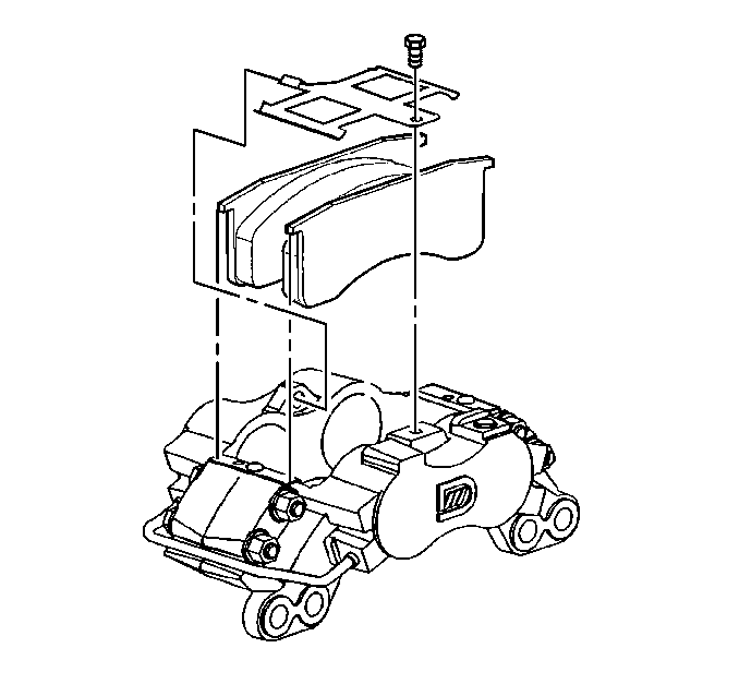
- Remove the brake pad retainer spring bolt.
- Remove the brake pad retainer spring.
- Using a suitable tool, lever between the disc brake pad and the rotor in order to compress the caliper pistons into the bores.
- Remove the inboard disc brake pad by lifting the disc brake pad straight up.
- Remove the outboard disc brake pad by lifting the disc brake pad straight up.
Important: Do not empty the reservoir.
Important: The disc brake caliper does NOT need to be removed in order to remove and install the disc brake pads.

Installation Procedure
- Install the new inboard brake pad to the caliper.
- Install the new outboard brake pad to the caliper.
- Install the brake pad retainer spring to the boss in the disc brake caliper.
- Install the brake pad retainer spring bolt.
- Pump the brake pedal several times in order to ensure that the pedal is firm and the brake linings are seated.
- Inspect the brake fluid level in the master cylinder. Refer to Master Cylinder Reservoir Filling in Hydraulic Brakes.
- Install the tire and wheel assembly. Refer to: Tire and Wheel Removal and Installation in Tires and Wheels.
- Lower the vehicle.

Notice: Use the correct fastener in the correct location. Replacement fasteners must be the correct part number for that application. Fasteners requiring replacement or fasteners requiring the use of thread locking compound or sealant are identified in the service procedure. Do not use paints, lubricants, or corrosion inhibitors on fasteners or fastener joint surfaces unless specified. These coatings affect fastener torque and joint clamping force and may damage the fastener. Use the correct tightening sequence and specifications when installing fasteners in order to avoid damage to parts and systems.
Tighten
Tighten the brake pad retainer spring bolt to 41 N·m (30 lb ft).
Important: Inspect the fluid level in the master cylinder reservoir after pumping the brake pedal.
