Camshaft Carrier Replacement Left Side
Removal Procedure
Tools Required
J 38613-A Camshaft Timing Clamps
- Remove the camshaft timing belt. Refer to Timing Belt Replacement .
- Disconnect the exhaust crossover pipe. Reposition the pipe.
- Remove the engine mount strut. Refer to Engine Mount Strut Replacement .
- Remove the thermostat housing from the intake manifold.
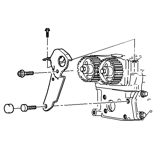
- Remove the front engine lift bracket.
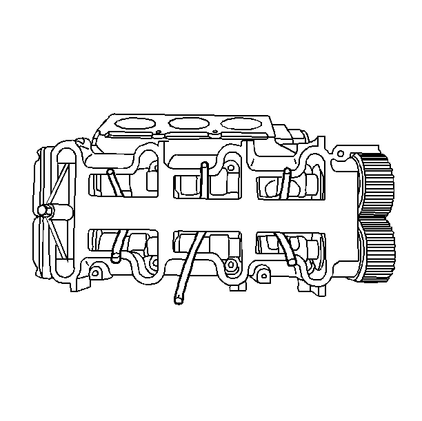
- Install the six fuel line hoses under the camshaft and between lifters to hold lifters in carrier.
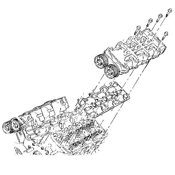
- Remove the camshaft carrier mounting bolts.
- Remove the camshaft carrier.
- Remove the gasket.

| • | Exhaust uses 6 inches x 3/16 inch fuel line hose. |
| • | Intake uses 6 inches x 5/32 inch fuel line hose. |

Installation Procedure
Tools Required
J 38613-A Camshaft Timing Clamps
- Remove the oil from the camshaft carrier to the cylinder head bolt holes, the holes closest to the exhaust manifold.
- Install the camshaft carrier gasket.
- Install the J 38613-A .
- Install the camshaft carrier.
- Install the camshaft carrier mounting bolts and nuts.
- Remove the lifter hold down hoses.
- Install the front engine lift bracket.
- Connect the thermostat housing to the intake manifold.
- Install the engine mount strut. Refer to Engine Mount Strut Replacement .
- Install the exhaust crossover pipe.
- Install the camshaft timing belt. Refer to Timing Belt Replacement .

Important: Remove the oil from the camshaft hold down tool hole in the carrier before installing and tightening the bolt.
Tighten
Tighten to 30 N·m (22 lb ft). The use of
petroleum jelly in the lifter bores, along with the use of the lifter hold
down hoses, will help keep the lifters in place.
Notice: Use the correct fastener in the correct location. Replacement fasteners must be the correct part number for that application. Fasteners requiring replacement or fasteners requiring the use of thread locking compound or sealant are identified in the service procedure. Do not use paints, lubricants, or corrosion inhibitors on fasteners or fastener joint surfaces unless specified. These coatings affect fastener torque and joint clamping force and may damage the fastener. Use the correct tightening sequence and specifications when installing fasteners in order to avoid damage to parts and systems.
Tighten
Tighten the bolts and nuts to 27 N·m (20 lb ft).


Camshaft Carrier Replacement Right Side
Removal Procedure
Tools Required
J 38613-A Camshaft Timing Clamps
- Remove the camshaft timing belt. Refer to Timing Belt Replacement .
- Install the six fuel line hoses under the camshaft and between lifters.
- Remove the camshaft carrier mounting bolts.
- Remove the camshaft carrier.
- Remove the gasket.

Important: Ensure that the six fuel line hoses are installed under the camshaft
and between lifters in order to hold lifters in carrier.
• Exhaust uses 6 inches x 3/16 inch fuel line hose. • Intake uses 6 inches x 5/32 inch fuel line hose.

Installation Procedure
Tools Required
J 38613-A Camshaft Timing Clamps
- Remove the oil from the camshaft carrier to the cylinder head bolt holes.
- Remove the gasket.
- Install the J 38613-A .
- The use of petroleum jelly in the lifter bores, along with the use of the lifter hold down hoses, will keep the lifters in place
- Install the camshaft carrier.
- Install the mounting bolts and nuts.
- Remove the lifter hold down hoses.
- Install the camshaft timing belt. Refer to Timing Belt Replacement .
Important: Remove the oil from the camshaft, hold the down the tool hole in carrier before installing and tightening bolt.
Tighten
Tighten to 30 N·m (22 lb ft).
Notice: Use the correct fastener in the correct location. Replacement fasteners must be the correct part number for that application. Fasteners requiring replacement or fasteners requiring the use of thread locking compound or sealant are identified in the service procedure. Do not use paints, lubricants, or corrosion inhibitors on fasteners or fastener joint surfaces unless specified. These coatings affect fastener torque and joint clamping force and may damage the fastener. Use the correct tightening sequence and specifications when installing fasteners in order to avoid damage to parts and systems.

Tighten
Tighten the bolts and nuts to 27 N·m (20 lb ft).

