Timing Belt Replacement Timing Procedure
Removal Procedure
Tools Required
| • | J 38613-A Camshaft Timing Clamps |
| • | J 38614 Camshaft Sprocket Holding Tool |
| • | J 36660-A Torque Angle Meter |
- Disconnect the negative battery cable. Refer to
Caution: Unless directed otherwise, the ignition and start switch must be in the OFF or LOCK position, and all electrical loads must be OFF before servicing any electrical component. Disconnect the negative battery cable to prevent an electrical spark should a tool or equipment come in contact with an exposed electrical terminal. Failure to follow these precautions may result in personal injury and/or damage to the vehicle or its components.
in General Information. - Remove the air cleaner duct. Refer to Engine Controls.
- Drain the coolant. Refer to SECTION 6B.
- Disconnect the control cables at the throttle body.
- Remove the fuel injector sight shield. Refer to Fuel Injector Sight Shield Replacement .
- Relieve the fuel pressure.
- Disconnect the fuel lines from the fuel rail.
- Remove the fuel mounting bracket.
- Remove the heater hose and the bracket at the lower intake manifold.
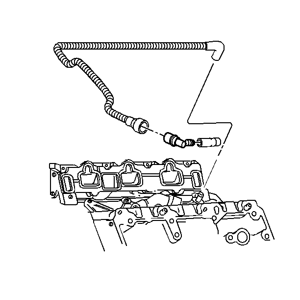
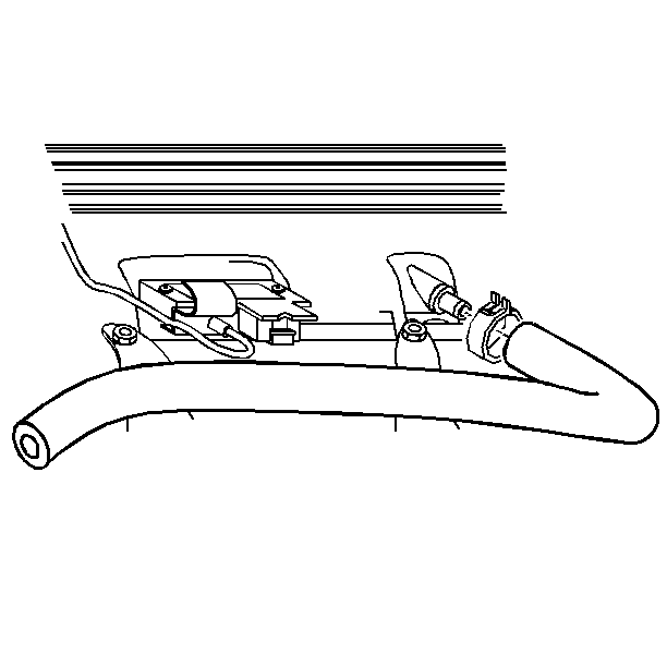
- Remove the PCV valve and the vacuum line from the throttle body.
- Disconnect the EGR valve electrical connector.
- Remove the EGR valve and the EGR bolts at the upper intake. Set the EGR valve aside.
- Disconnect the canister purge solenoid electrical connector.
- Disconnect the MAP sensor electrical connector.
- Disconnect the vacuum lines from the upper intake manifold tee.
- Remove the wiring loom bracket for the rear bank spark plug wires.
- Disconnect the power brake vacuum hose.
- Remove the nuts at the upper intake manifold support bracket.
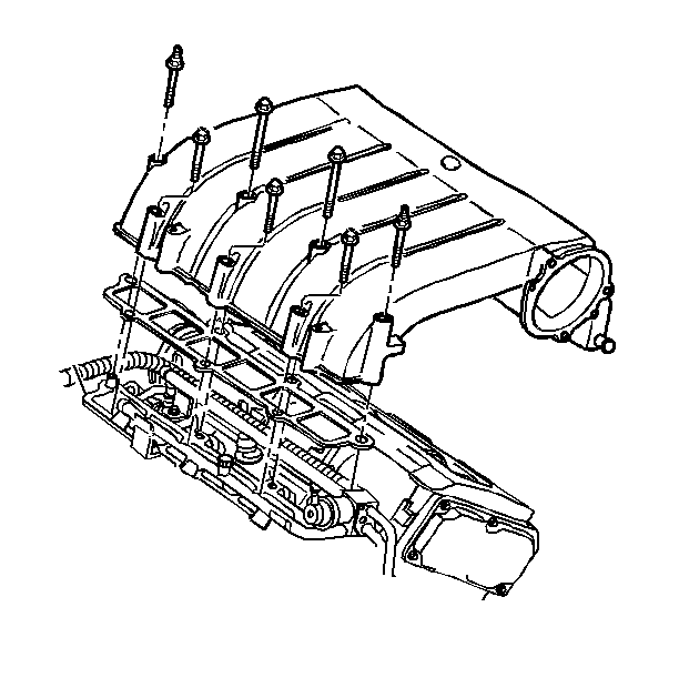
- Remove the upper intake manifold. Refer to Upper Intake Manifold Replacement .
- Remove the coolant recovery reservoir.
- Remove the drive belt. Refer to Drive Belt Replacement .
- Remove the drive belt tensioner. Refer to Drive Belt Tensioner Replacement .
- Remove the power steering pump. Refer to SECTION 3B.
- Disconnect the PCM electrical connectors.
- Disconnect the spark plug wires from the spark plugs.
- Remove the wiring harness cover at the right strut tower.
- Remove the fuel line bracket.
- Remove the left timing belt cover. Refer to Timing Belt Cover Replacement .
- Remove the right timing belt cover. Refer to Timing Belt Cover Replacement .
- Disconnect the breather hose from the rear camshaft cover.
- Disconnect the crankshaft vent from the breather manifold.
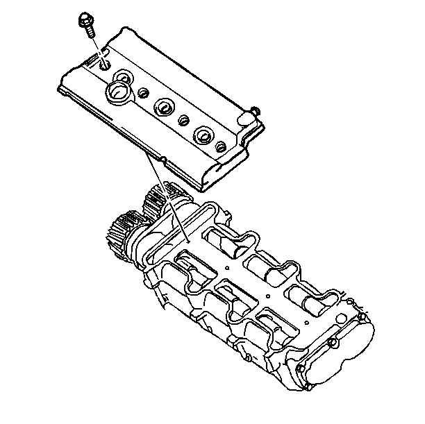
- Remove the camshaft carrier covers.
- Remove the bolts and the side plate from the timing belt tensioner actuator.
- Rotate the drive belt tensioner actuator from the tensioner actuator pulley socket and out of the mounting base.
- Remove the timing belt tensioner actuator pulley.
- Position the timing belt tensioner actuator in a vertical position within a vise (rod tip down).
- Lightly clamp the tensioner actuator in a vise.
- Drain the oil in the tensioner actuator to the boot end for at least 5 minutes before refilling the actuator.
- Straighten out a standard paper clip (0.032 in diameter with no serrations) to a minimum straight length of 47 mm (1.85 in).
- Form a double loop in the remaining end of the paper clip.
- Remove the rubber end plug from the rear of the tensioner actuator. Do not remove the vent plug.
- Push the paper clip through the center hole in the vent plug and into the pilot hole.
- Insert a small screwdriver into the screw slot inside the tensioner actuator and behind the rubber end plug.
- Retract the tensioner actuator plunger by rotating the screw in a clockwise direction until it is fully retracted.
- Push on the paper clip and slowly rotate the screw in a counterclockwise motion until the paper clip engages.
- Remove the timing belt.
- Rotate the crankshaft so the number one cylinder is at TDC (top dead center).
- Mark the timing indicator with white paint (or equivalent) on the crankshaft balancer and front cover.
- Position the camshaft so that the flat spots are "up" for the installation of the J 38613-A .
- Install the J 38613-A on both camshaft carriers.
- Remove the camshaft sprocket bolts and taper lock rings.
- Remove the camshaft sprockets by lightly tapping on them with a soft faced hammer.
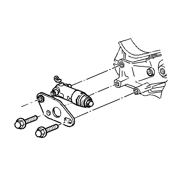
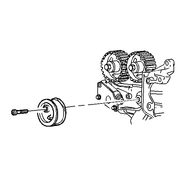
Notice: Do not install the rod tip or the tensioner actuator boot in the jaws of a vise or damage to the assembly may occur.
Important: Do not lose or damage the tapered bushing between the tensioner actuator and the mounting base while removing the tensioner actuator.
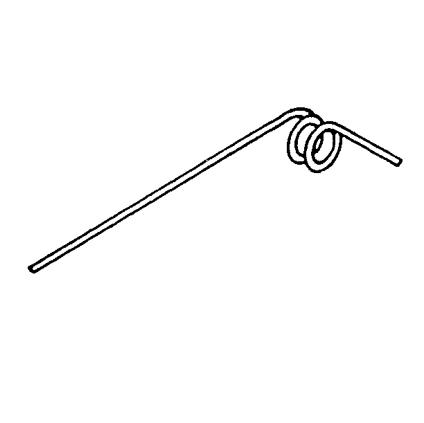
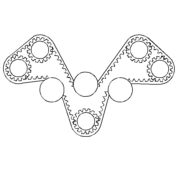
Important: Remove the timing marks from the camshaft and the intermediate shaft sprockets.
Align the timing mark on the crankshaft balancer with the cast arrow on the front cover, to the upper right of the crankshaft balancer (2 o'clock position).
Notice: Ensure that the bolt hole is free of any debris before installing the J 38613-A or the camshaft carrier may be damaged.
Installation Procedure
Tools Required
J 38613-A Camshaft Timing Clamps
- Install the camshaft sprockets finger tight.
- Install the timing belt. Do this by routing the timing belt in a counterclockwise motion around the camshaft sprockets.
- Install the timing belt tensioner actuator pulley.
- If any tensioner oil has been lost, refill the tensioner actuator with a SAE 5W30 Mobil 1 synthetic engine oil, or equivalent, through the end hole.
- Fill the tensioner actuator to the bottom of the plug hole only when the tensioner actuator is fully retracted and the pin is installed.
- Install the rubber end plug at the rear of the tensioner actuator. Push the rubber end plug until the plug is flush and snapped into place.
- Check to make sure that the rubber end plug has sealed against the tensioner actuator case.
- Install the timing belt tensioner actuator bushing into the side plate.
- Inspect the tensioner bushings and the appropriate holes for dirt or any foreign material. Do not lubricate the tensioner bushings or the holes.
- Install the tensioner actuator.
- Install the tensioner actuator side plate.
- Pull the lock pin. Discard the pin.
- Retighten the tensioner pulley 15 N·m (11 lb ft) counterclockwise in order to seat the pulley into the timing belt.
- Install both of the right hand (rear bank) camshaft sprockets.
- Remove the J 38613-A from the right-hand (rear bank) side of the camshaft carrier.
- Rotate the crankshaft 360° clockwise while looking at the front of the engine. Align the crankshaft reference marks.
- Check to make sure that both of the right-hand (rear bank) camshaft flats are down.
- Install both of the left-hand (front bank) camshaft sprockets.
- Remove the J 38613-A from the left-hand (front bank)
- Rotate the crankshaft 720° clockwise while looking at the front of the engine. Do this in order to seat the timing belt and verify the correct timing.
- Check to ensure that both of the camshaft flatspots are up on one bank and down on the opposing bank.
- Install the left side camshaft carrier cover. Refer to Camshaft Carrier Cover Replacement .
- Install the right side camshaft carrier cover. Refer to Camshaft Carrier Cover Replacement
- Connect the breather hose to the rear camshaft cover.
- Connect the crankshaft vent to the breather manifold.
- Install the left camshaft timing belt cover. Refer to Timing Belt Cover Replacement .
- Install the right camshaft timing belt cover. Refer to Timing Belt Cover Replacement .
- Install the fuel line bracket and the fuel line bracket bolt.
- Install the wiring harness cover at the right strut tower.
- Install the spark plug wires.
- Install the PCM electrical connectors. Refer to SECTION 6E3.
- Connect the power steering lines to the power steering pump. Refer to SECTION 3B.
- Install the accessory drive belt. Refer to Drive Belt Replacement .
- Install the accessory drive belt tensioner. Refer to Drive Belt Tensioner Replacement .
- Install the coolant recovery reservoir.
- Install the upper intake manifold gasket.
- Install the upper intake manifold.
- Install the upper intake manifold bolts.
- Install the upper intake manifold support bracket nuts.
- Install the power brake vacuum hose.
- Install the wiring loom bracket for the rear spark plug wires.
- Connect the vacuum lines to the upper intake manifold tee.
- Install the canister purge solenoid.
- Install the MAP sensor.
- Install the EGR valve at the upper intake.
- Install the EGR bolts.
- Install the EGR valve.
- Connect the PCV valve and the vacuum line to the throttle body.
- Install the heater hose and the bracket to the lower intake manifold. Refer to SECTION 6B.
- Install the fuel line bracket and bolt.
- Connect the fuel pipes to the fuel rail. Refer to SECTION 6C.
- Install the fuel injector sight shield. Refer to Fuel Injector Sight Shield Replacement .
- Connect the control cables at the throttle body.
- Install the air cleaner duct. Refer to Engine Controls.
- Refill the coolant. Refer to SECTION 6B.
- Refill the power steering fluid. Refer to SECTION 3B.
- Connect the negative battery cable.
Important: Check to make sure that the timing belt teeth are fully engaged with the camshaft sprockets.
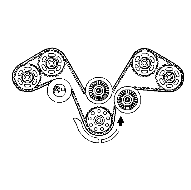

Tighten
Tighten the tensioner actuator pulley bolt/screw to 50 N·m
(37 lb ft).
Notice: Use the correct fastener in the correct location. Replacement fasteners must be the correct part number for that application. Fasteners requiring replacement or fasteners requiring the use of thread locking compound or sealant are identified in the service procedure. Do not use paints, lubricants, or corrosion inhibitors on fasteners or fastener joint surfaces unless specified. These coatings affect fastener torque and joint clamping force and may damage the fastener. Use the correct tightening sequence and specifications when installing fasteners in order to avoid damage to parts and systems.
Important: Check to make sure that the tapered fulcrum of the tensioner actuator is properly seated in the bracket bushing. Rotate the tensioner pulley into the timing belt a maximum of 15 N·m (11 lb ft) in order to allow the engagement of the actuator shaft into the pulley arm socket.

Tighten
Tighten the tensioner actuator side plate bolts to 25 N·m
(18 lb ft).
Tighten
Tighten the camshaft sprocket bolts to 130 N·m (96 lb ft).
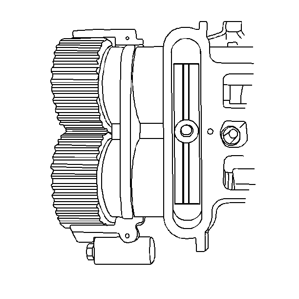
Tighten
Tighten the left hand camshaft sprockets to 130 N·m (96 lb ft).

Tighten
Tighten the upper intake manifold bolts to 26 N·m (19 lb ft).
Tighten
Tighten the upper intake manifold support bracket nuts to 25 N·m
(18 lb ft).

