Body Side Inner Panel Extension Replacement Sedan
Removal Procedure
- Disable the SIR system. Refer to SIR Disabling and Enabling .
- Disconnect the negative battery cable. Refer to Battery Negative Cable Disconnection and Connection .
- Remove the rear bumper fascia. Refer to Rear Bumper Fascia Replacement .
- Remove the rear impact bar. Refer to Rear Bumper Impact Bar Replacement .
- Remove the tail lights. Refer to Parking and Turn Signal Lamp Replacement .
- Remove the spare wheel and emergency kit from the rear compartment.
- Remove the spare wheel and tyre carrier. Refer to Spare Wheel Carrier Replacement .
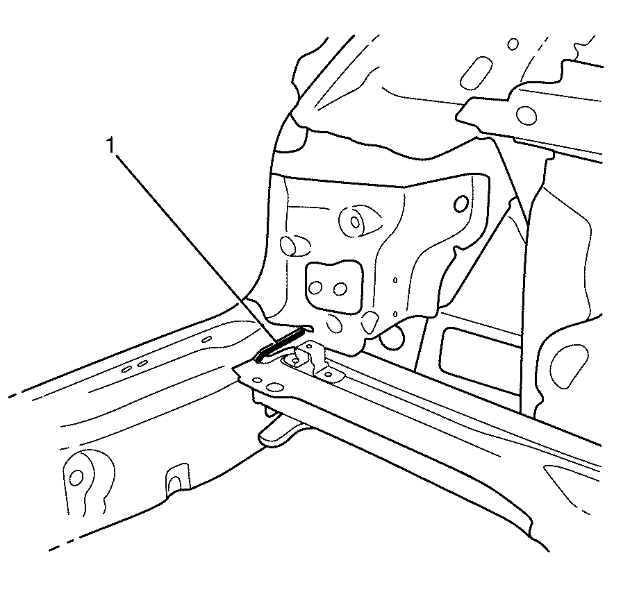
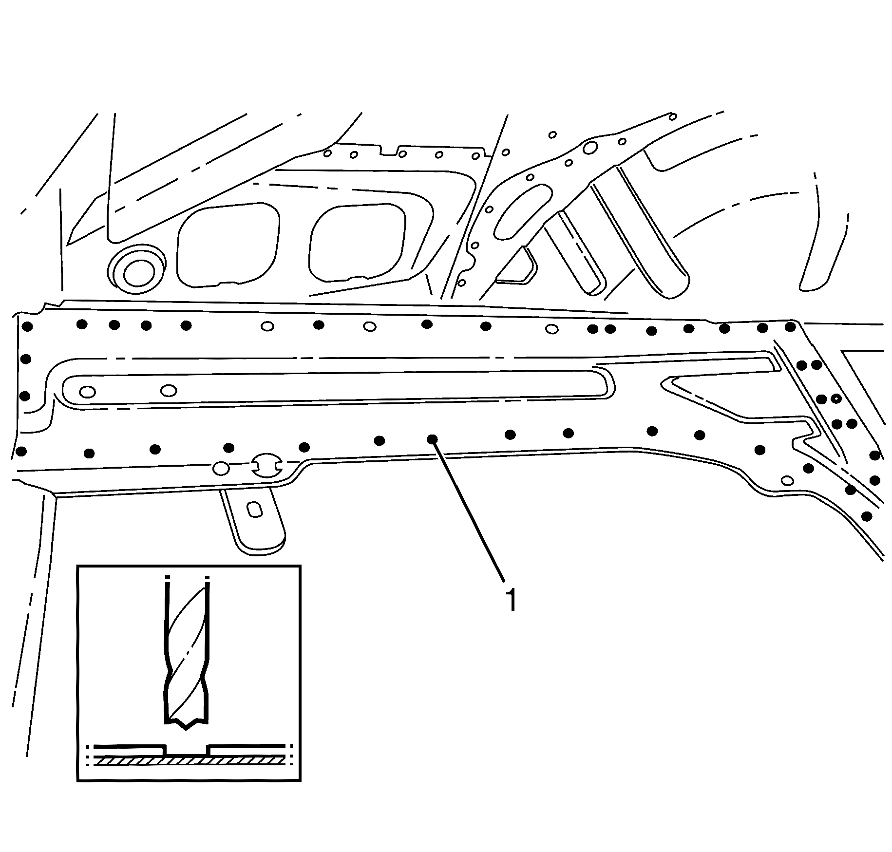
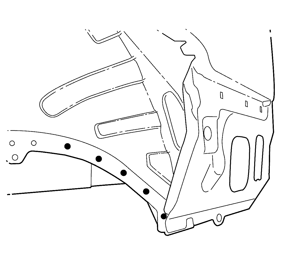
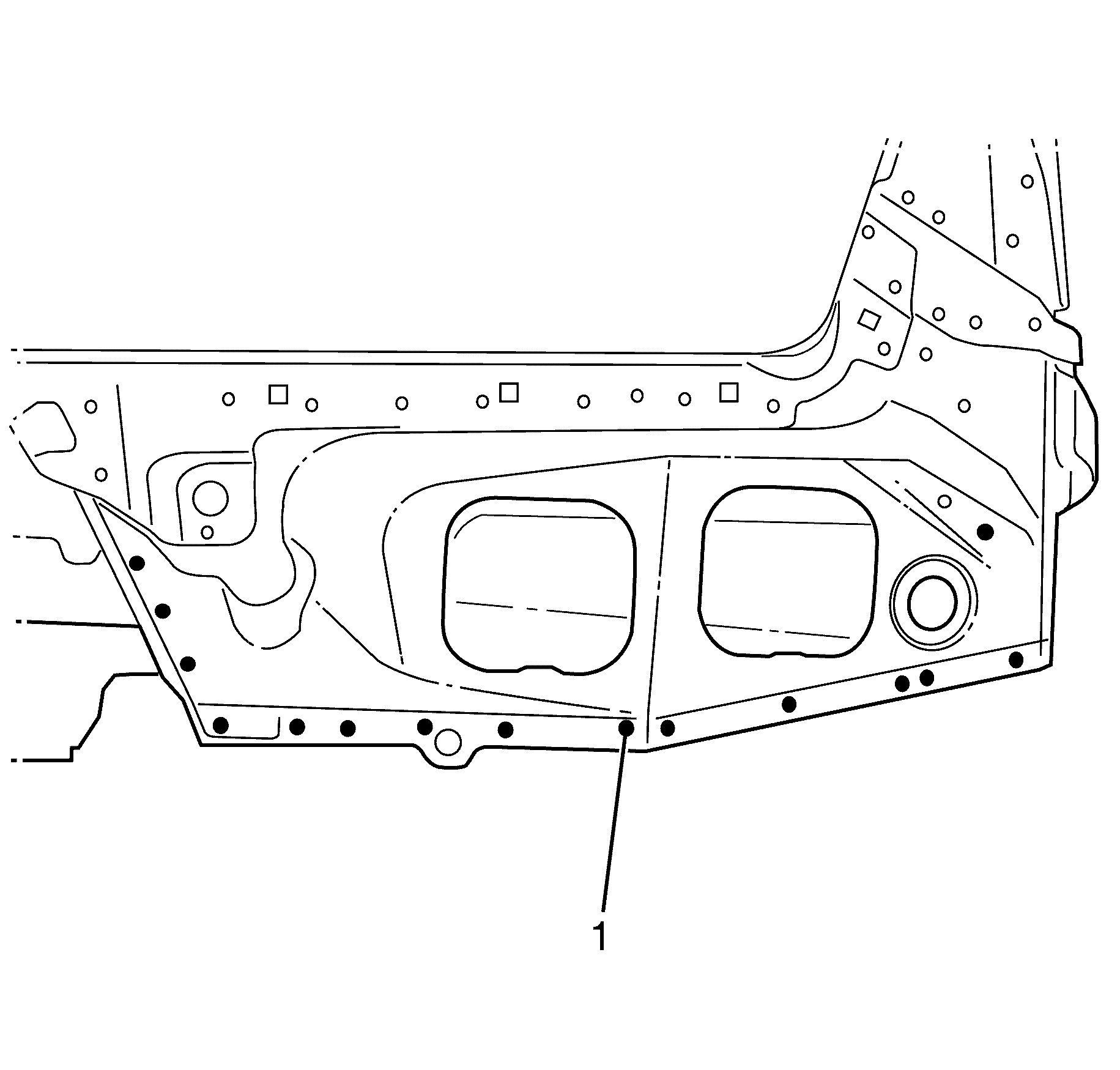
- Locate, mark and drill out the spot welds (1)in the side extension panel to the rear chassis rail.
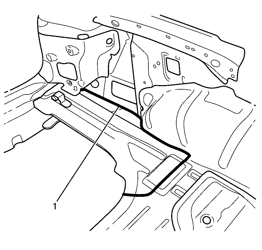
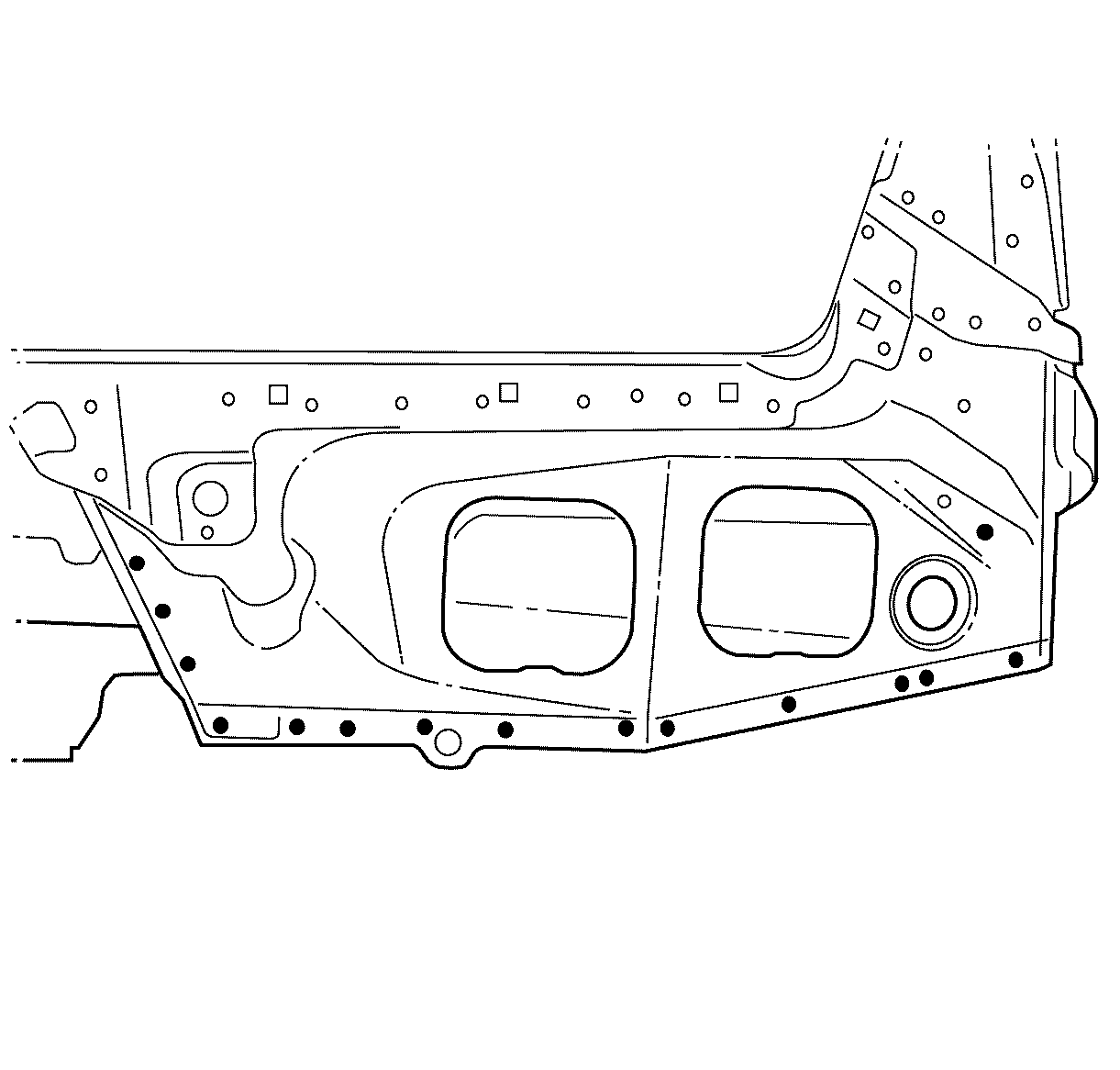
- Locate, mark and drill out the spot welds (1) in the side extension panel to the rear extension panel.
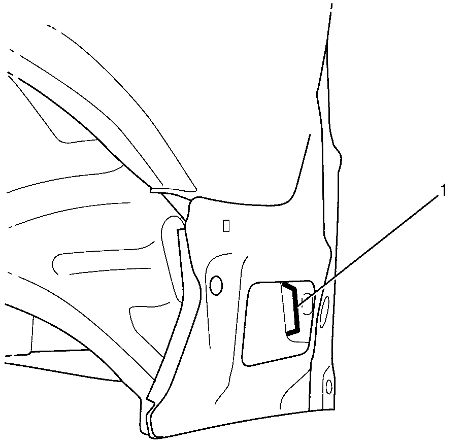
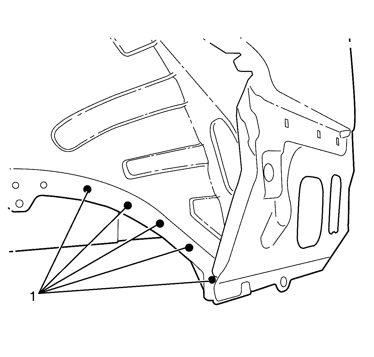
- Locate, mark and drill out the spot welds (1) in the side extension panel to the rear extension panel.
Caution: Refer to Approved Equipment for Collision Repair Caution in the Preface section.
Caution: Refer to Foam Sound Deadeners Caution in the Preface section.
Caution: Refer to Battery Disconnect Caution in the Preface section.
Installation Procedure
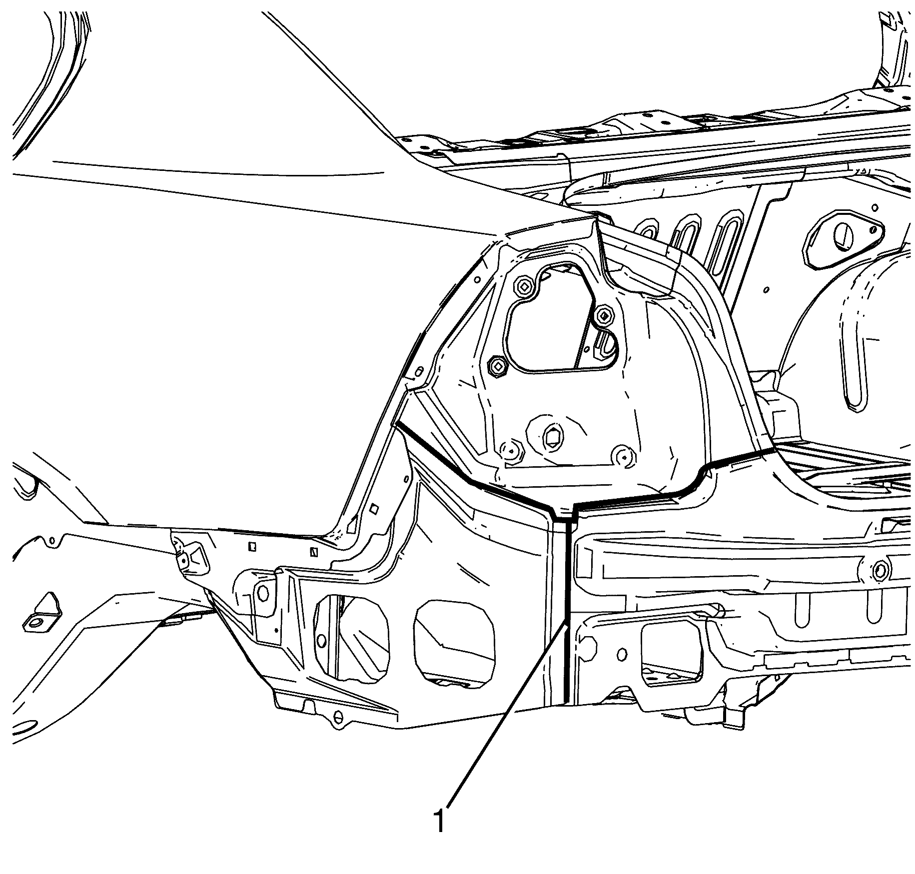
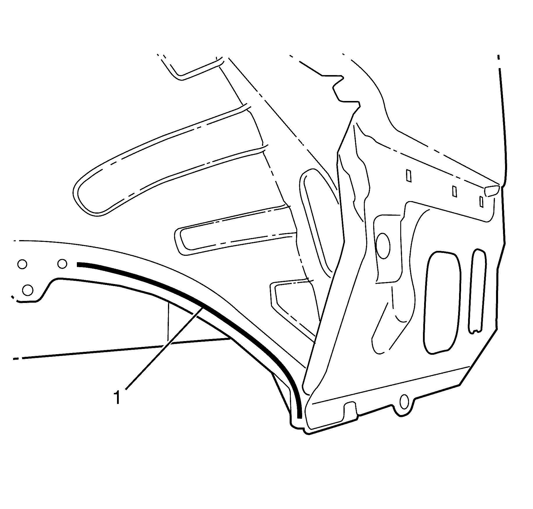
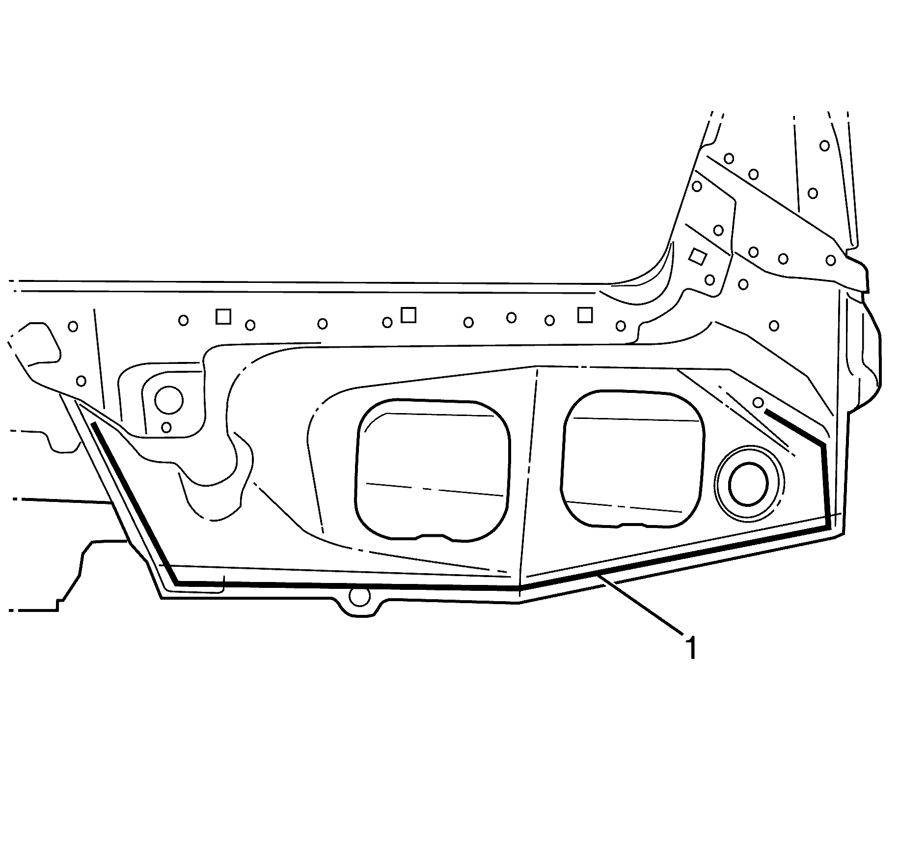
- Apply the primary sealer (1) GM6449G or equivalent along the tail lamp filler panel and rear extension panel to the rear quarter panel.
- Apply the primary sealer (1) GM6449G or equivalent along the inner side extension panel.
- Apply the primary sealer (1) GM6449G or equivalent along the outer side extension panel.
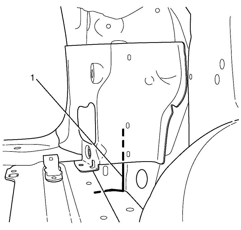
- Weld (1) the rear extension panel to the side extension panel.
- Weld (1) the rear extension panel to the side extension panel.
- Weld (1) the side extension panel to the rear chassis rail.
- Apply the sealers and anti-corrosion materials to the repair area, as necessary. Refer to Anti-Corrosion Treatment and Repair .
- Paint the repaired area. Refer to Basecoat/Clearcoat Paint Systems .
- Install the spare wheel and tyre carrier. Refer to Spare Wheel Carrier Replacement .
- Install the tail lights. Refer to Parking and Turn Signal Lamp Replacement .
- Install the rear impact bar. Refer to Rear Bumper Fascia Insert Replacement .
- Install the rear bumper fascia. Refer to Rear Bumper Fascia Replacement .
- Install the spare wheel and emergency kit from the rear compartment.
- Connect the negative battery cable. Refer to Battery Negative Cable Disconnection and Connection .
- Enable the SIR system. Refer to SIR Disabling and Enabling .
- If re-programming is required. Refer to Control Module References .
Important: If the location of the original spot weld holes can not be determined, or if structural weld-thru adhesive is present, space the puddle weld holes every 32 mm (1¼ in).
Important: Spot welding is the preferred method for attaching panels and should be used wherever possible. A puddle weld should be performed where your spot welder is unable to reach.
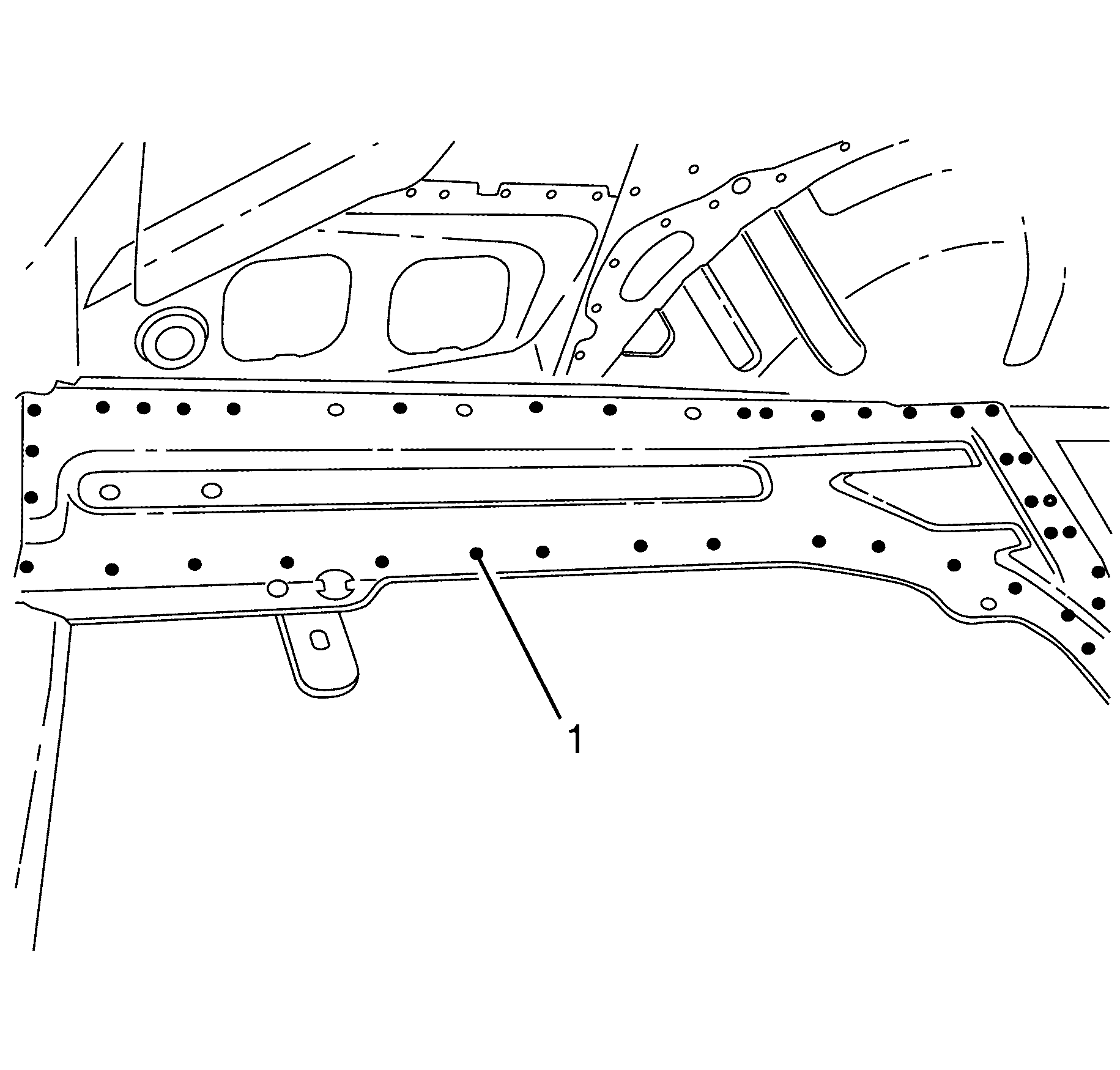
Caution: Refer to Battery Disconnect Caution in the Preface section.
Body Side Inner Panel Extension Replacement Sportwagon
Removal Procedure
- Disable the SIR system. Refer to SIR Disabling and Enabling.
- Disconnect the negative battery cable. Refer to Battery Negative Cable Disconnection and Connection.
- Remove the rear bumper fascia. Refer to Rear Bumper Fascia Replacement.
- Remove the rear impact bar. Refer to Rear Bumper Impact Bar Replacement.
- Remove the rear end trim finish panel. Refer to Rear End Trim Finish Panel Replacement.
- Remove the rear compartment floor panel carpet. Refer to Rear Compartment Floor Panel Carpet Replacement.
- Remove the load floor stationary panel carpet. Refer to Load Floor Stationary Panel Carpet Replacement.
- Remove the load floor front panel carpet. Refer to Load Floor Front Panel Carpet Replacement.
- Remove the rear bumper bracket. Refer to Rear Bumper Bracket Replacement.
- Remove the liftgate weatherstrip. Refer to Liftgate Weatherstrip Replacement.
- Remove the quarter inner trim finish panel. Refer to Quarter Inner Trim Finish Panel Replacement.
- Remove the battery. Refer to Battery Replacement.
- Remove the battery tray. Refer to Battery Tray Replacement.
- Remove the pressure relief valve. Refer to Pressure Relief Valve Replacement.
- Remove the tail lights. Refer to Tail Lamp Assembly and /or Backup, Sidemarker, Stop, Turn Signal Bulb Replacement.
- Remove the liftgate. Refer to Liftgate Replacement.
- Remove the spare wheel and emergency kit from the rear compartment.
- Remove the spare wheel carrier. Refer to Spare Wheel Carrier Replacement.
- Remove the rear end filler panel. Refer to Rear End Panel Filler Replacement
- Remove the sealers and anti-corrosion materials from the repair area, as necessary. Refer to Anti-Corrosion Treatment and Repair.
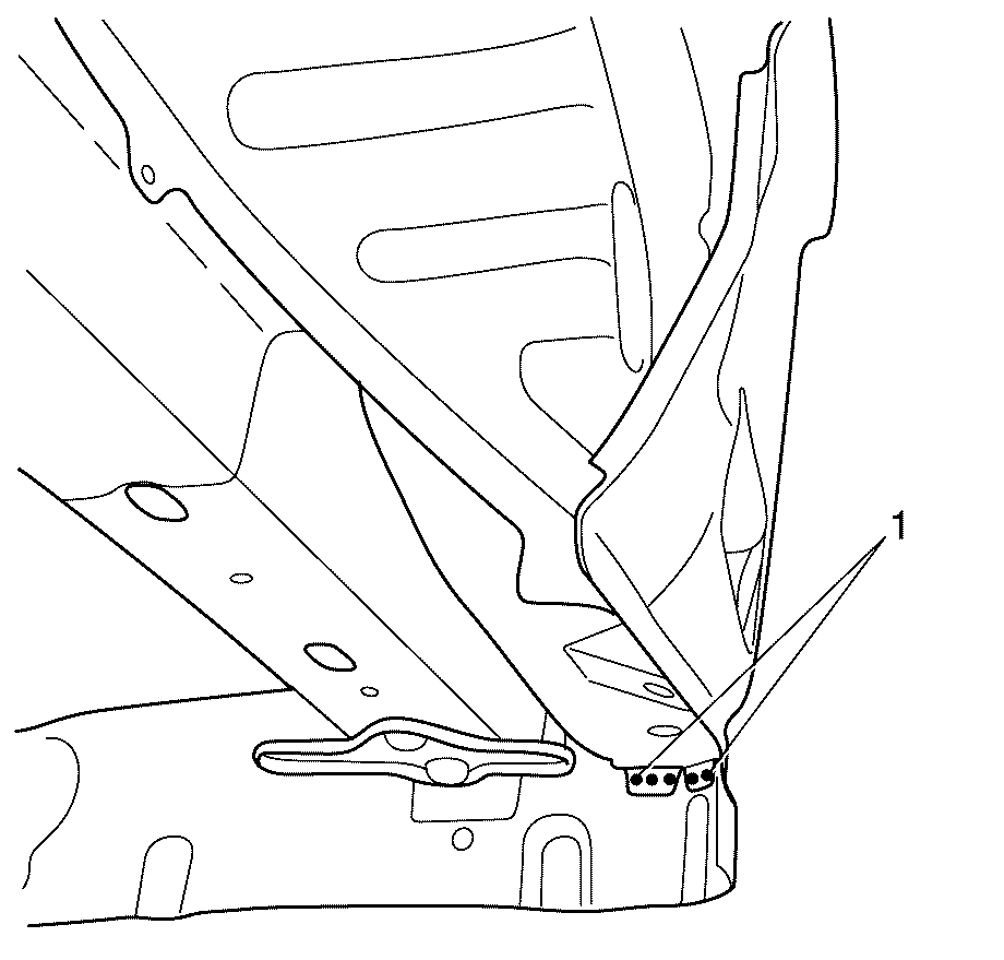
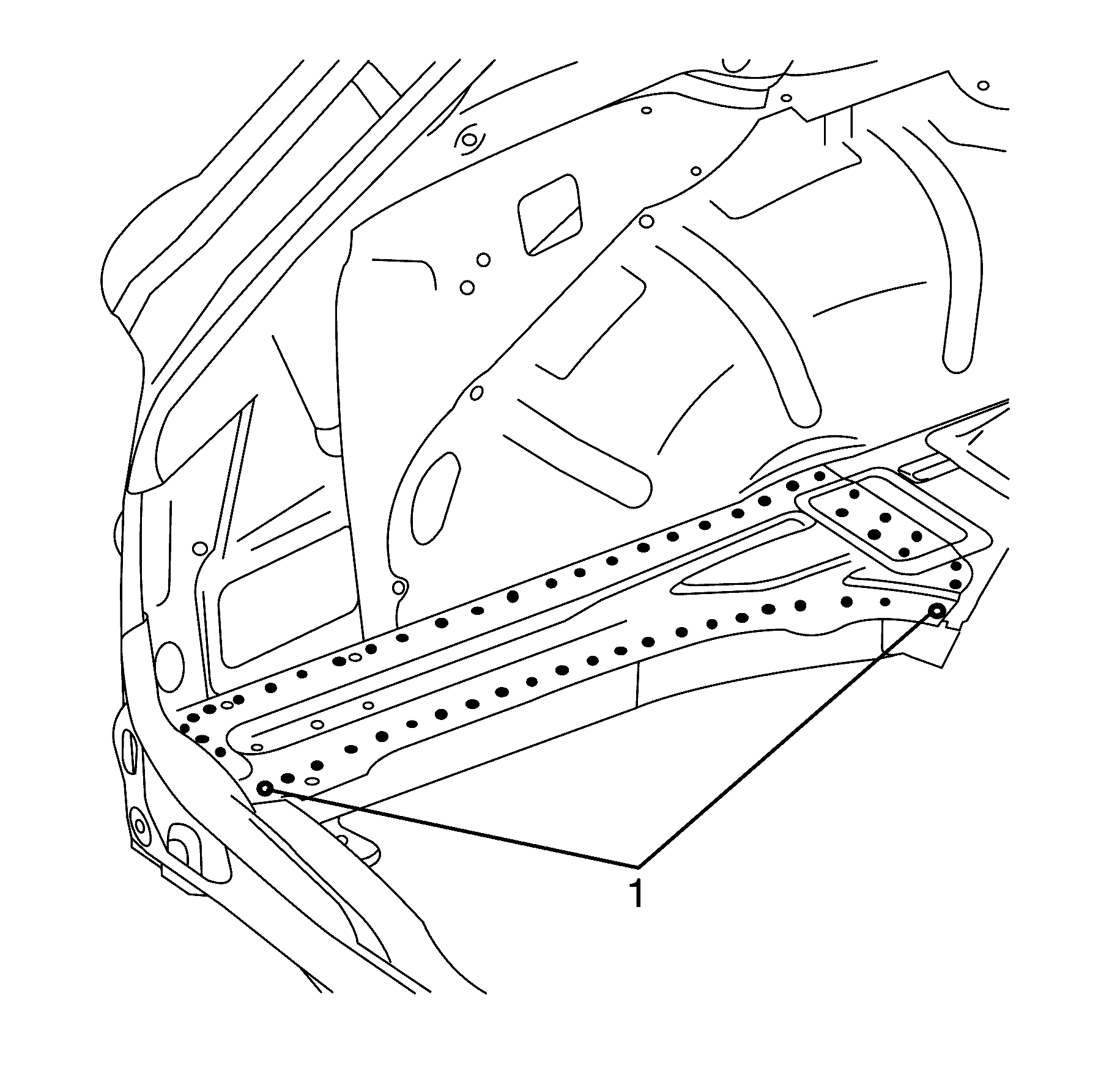
- Locate, mark and drill out the spot welds (1) in the body side inner panel extension to the rear chassis rail.
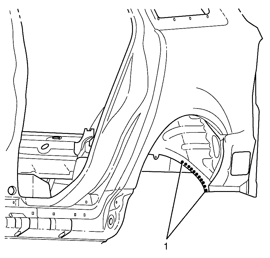
- Locate, mark and drill out the spot welds (1) in the body side inner panel extension to the body side panel assembly.
- Locate, mark and drill out the spot welds (1) in the body side inner panel extension to the body side panel assembly.
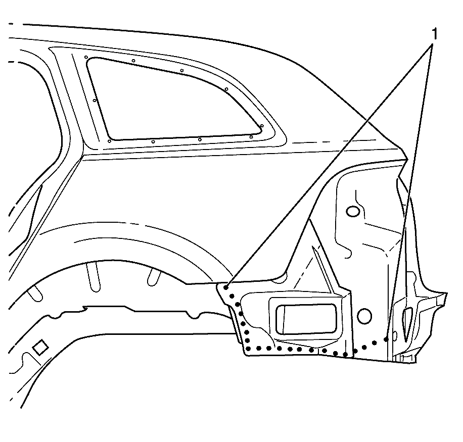
- Locate, mark and drill out the spot welds (1) in the body side inner panel extension to the rear end panel assembly.
- Remove the body side inner panel extension from the vehicle.
Caution: Refer to Approved Equipment for Collision Repair Caution in the Preface section.
Caution: Refer to Safety Glasses Caution in the Preface section.
Caution: Refer to Foam Sound Deadeners Caution in the Preface section.
Caution: Refer to Battery Disconnect Caution in the Preface section.
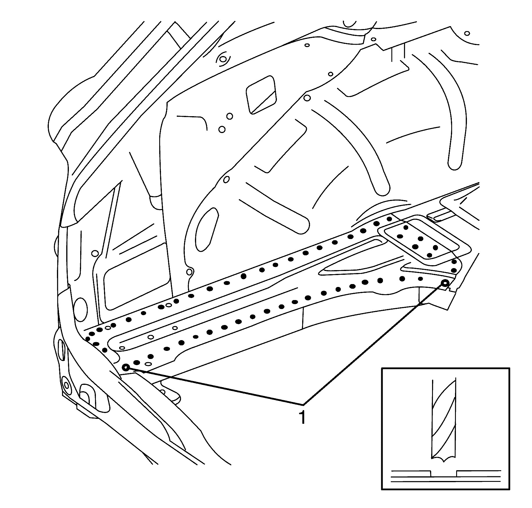
Important: Note the number and location of welds for installation on the new body side inner panel extension.
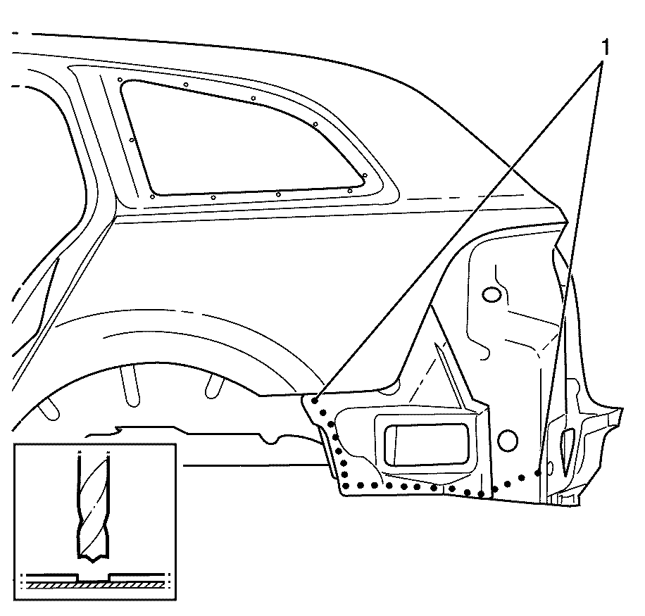
Important: Note the number and location of welds for installation on the new body side inner panel extension.
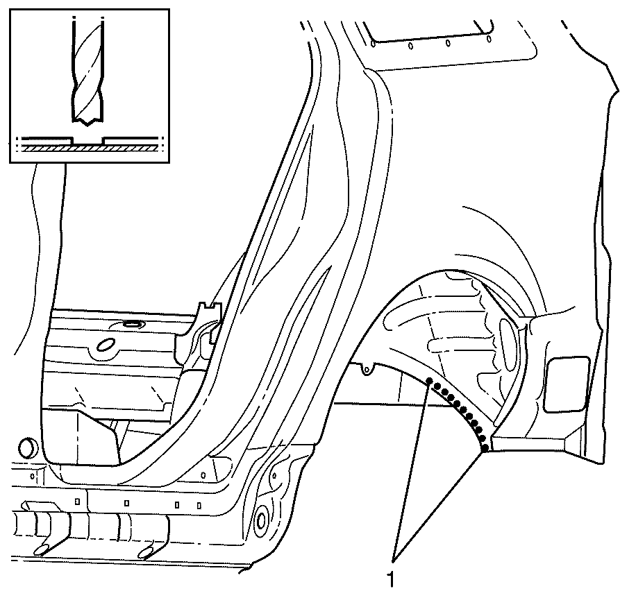
Important: Note the number and location of welds for installation on the new body side inner panel extension.
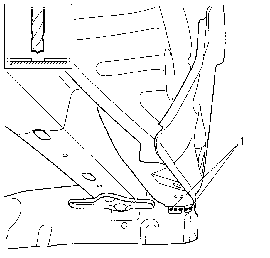
Important: Note the number and location of welds for installation on the new body side inner panel extension.
Installation Procedure
- Drill 8 mm (5/16 in) plug weld holes as necessary in the locations noted when disassembling.
- Clean and prepare the mating surfaces of both parts of the body side panel assembly.
- Apply structural adhesive (1) GM6449G or equivalent to the mating surfaces of the body side inner panel extension and rear end panel assembly.
- Position the new body side inner panel extension to the vehicle.
- Weld (1) the body side inner panel extension to the rear end panel assembly.
- Weld (1) the body side inner panel extension to the body side panel assembly.
- Weld (1) the body side inner panel extension to the body side panel assembly.
- Weld (1) the body side inner panel extension to the rear chassis rail.
- Apply secondary sealer (1) GM9984532 or equivalent along the rear edge of the body side inner panel extension.
- Apply secondary sealer (1) GM9984532 or equivalent along the edge of the body side inner panel extension.
- Apply secondary sealer (1) GM9984532 or equivalent to the rear compartment floor panel rail.
- Apply secondary sealer (1) GM9984532 or equivalent to the body tail-lamp filler panel.
- Install the rear end filler panel. Refer to Rear End Panel Filler Replacement
- Apply any sealers and anti-corrosion materials to the repair area noted on disassembly. Refer to Anti-Corrosion Treatment and Repair.
- Paint the repaired area. Refer to Basecoat/Clearcoat Paint Systems.
- Install the spare wheel carrier. Refer to Spare Wheel Carrier Replacement.
- Install the spare wheel and emergency kit from the rear compartment.
- Install the liftgate. Refer to Liftgate Replacement.
- Install the tail lights. Refer to Tail Lamp Assembly and /or Backup, Sidemarker, Stop, Turn Signal Bulb Replacement.
- Install the pressure relief valve. Refer to Pressure Relief Valve Replacement.
- Install the battery tray. Refer to Battery Tray Replacement.
- Install the battery. Refer to Battery Replacement.
- Install the quarter inner trim finish panel. Refer to Quarter Inner Trim Finish Panel Replacement.
- Install the liftgate weatherstrip. Refer to Liftgate Weatherstrip Replacement.
- Install the rear bumper bracket. Refer to Rear Bumper Bracket Replacement.
- Install the load floor front panel carpet. Refer to Load Floor Front Panel Carpet Replacement.
- Install the load floor stationary panel carpet. Refer to Load Floor Stationary Panel Carpet Replacement.
- Install the rear compartment floor panel carpet. Refer to Rear Compartment Floor Panel Carpet Replacement.
- Install the rear end trim finish panel. Refer to Rear End Trim Finish Panel Replacement.
- Install the rear impact bar. Refer to Rear Bumper Impact Bar Replacement.
- Install the rear bumper fascia. Refer to Rear Bumper Fascia Replacement.
- Connect the negative battery cable. Refer to Battery Negative Cable Disconnection and Connection.
- Enable the SIR system. Refer to SIR Disabling and Enabling.
Important: Spot welding is the preferred method for attaching panels and should be used whenever possible. A plug weld should only be performed where spot welding is not possible.
Important: Ensure that all factory welds are replaced in their original locations.
Important: Ensure that all structural adhesives are replaced in their original locations.
Important: If the location of the original plug weld holes cannot be determined, or if structural weld-thru adhesive is present, space the plug weld holes every 32 mm (1¼ in).
Important: Follow the adhesive manufacturer's instructions during the assembly process. Heat must be applied as per the manufacturer's specifications to cure the adhesives and to expand the sealing baffles.
Important: Secondary sealer must be applied to the perimeter of all flanges. Secondary sealer must be applied to all welds/joints that were originally covered by secondary sealer.
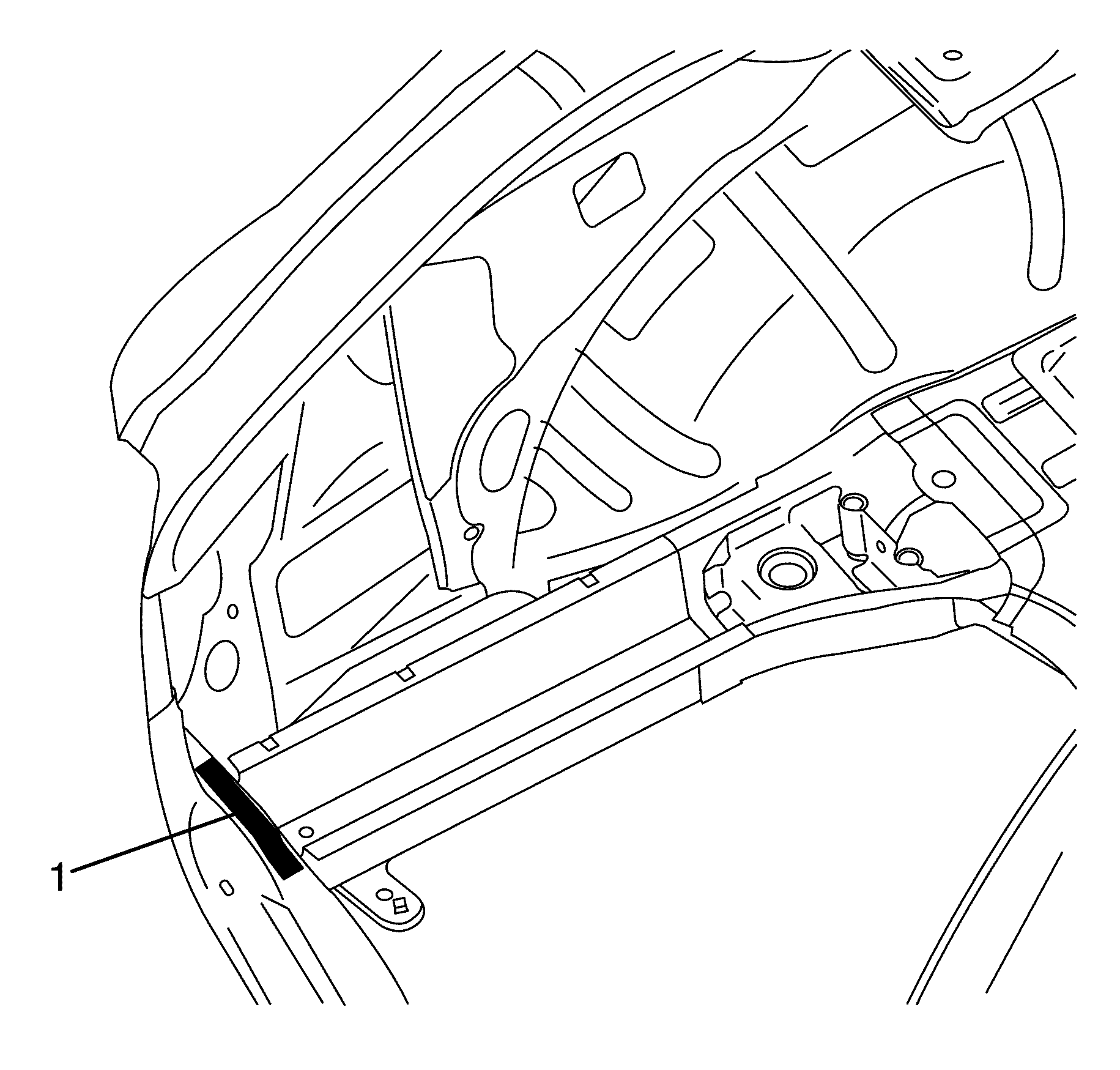
Important: As the new body side inner panel extension is installed to the vehicle, structural adhesive should be visible on the outside edges of both surfaces (squeezed out when pushed together).
