For 1990-2009 cars only
Tools Required
J 39400-A Halogen Leak Detector
Removal Procedure
- Disconnect the negative battery cable. Refer to Battery Negative Cable Disconnection and Connection in Engine Electrical.
- Drain the coolant. Refer to Cooling System Draining and Filling in Engine Cooling.
- Remove the inlet heater hose at the heater core. Refer to Heater Inlet Hose Replacement in Heating, Ventilation, and Air Conditioning.
- Remove the outlet heater hose at the heater core. Refer to Heater Outlet Hose Replacement in Heating, Ventilation, and Air Conditioning.
- Recover the refrigerant. Refer to Refrigerant Recovery and Recharging in Heating, Ventilation, and Air Conditioning.
- Remove the suction hose at the thermostatic expansion valve (TXV). Refer to Thermal Expansion Valve Replacement in Heating, Ventilation, and Air Conditioning.
- Remove the liquid line at the TXV. Refer to Thermal Expansion Valve Replacement in Heating, Ventilation, and Air Conditioning.
- Remove and discard the sealing washers.
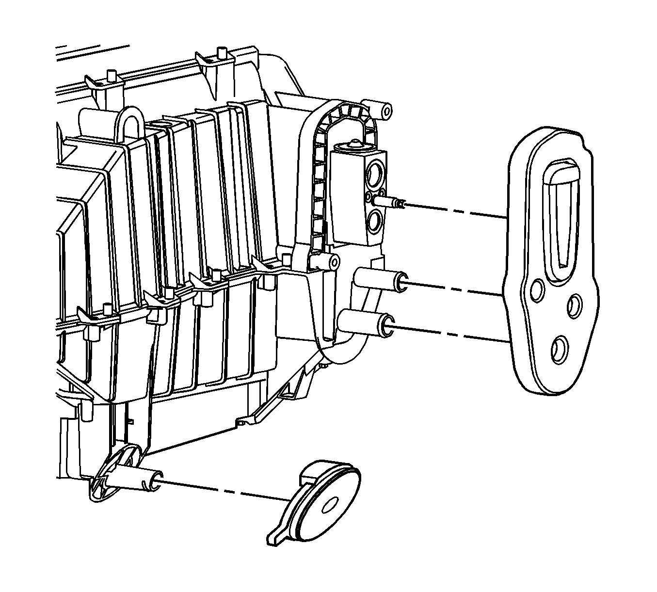
- Disconnect the HVAC module to front of dash plate bolts.
- Remove the right console trim panel. Refer to Front Floor Console Side Trim Panel Replacement - Right Side .
- Remove the left console trim panel. Refer to Front Floor Console Side Trim Panel Replacement - Left Side .
- Remove the console. Refer to Console Replacement .
- Remove the left closeout panel. Refer to Instrument Panel Insulator Panel Replacement - Left Side .
- Remove both instrument panel (I/P) outer trim panels. Refer to Instrument Panel Outer Trim Cover Replacement .
- Remove the I/P to the body wire harness and antenna LH connectors.
- Remove the I/P to the wire harness RH connectors.
- Remove the knee bolster. Refer to Knee Bolster Replacement .
- Remove the accelerator pedal. Refer to Accelerator Pedal Replacement in Engine Controls - 2.2L.
- Remove the steering column to the I/P wire harness connector. Refer to Steering Column Replacement in Steering Wheel and Column.
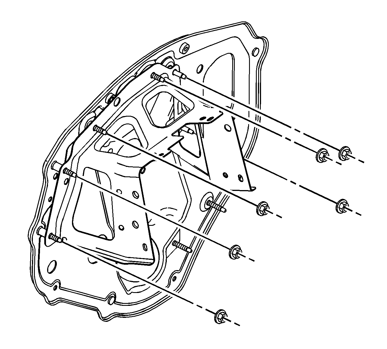
- Remove the crush bracket to the front of dash plate nuts.
- Remove the upper steering column shroud from the lower shroud. Refer to Steering Column Trim Covers Replacement in Steering Wheel and Column.
- Remove the stalk switches and the SIR coil connectors. Refer to Turn Signal Multifunction Switch Replacement in Steering Wheel and Column.
- Position the steering wheel in full forward telescoping position.
- Position the front seat in the full rearward position.
- Remove the steering column mounting bolts. Refer to Steering Column Replacement in Steering Wheel and Column.
- Lower the steering column to the floor.
- Remove the brake pedal assembly. Refer to Brake Pedal Assembly Replacement in Hydraulic Brakes.
- Remove the body control module (BCM). Refer to Body Control Module Replacement in Computer/Integrating Systems.
- Remove the center support bracket floor bolts. Refer to Instrument Panel Center Support Bracket Replacement
- Remove the shifter assembly. Refer to Transmission Control Replacement in Automatic Transaxle - 4T40-E/4T45-E.
- Remove both windshield pillar garnish moldings. Refer to Windshield Pillar Garnish Molding Replacement in Interior Trim.
- Remove the I/P upper trim panel. Refer to Instrument Panel Upper Trim Panel Replacement .
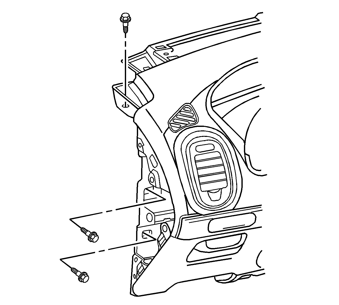
- Remove the I/P body LH bolts.
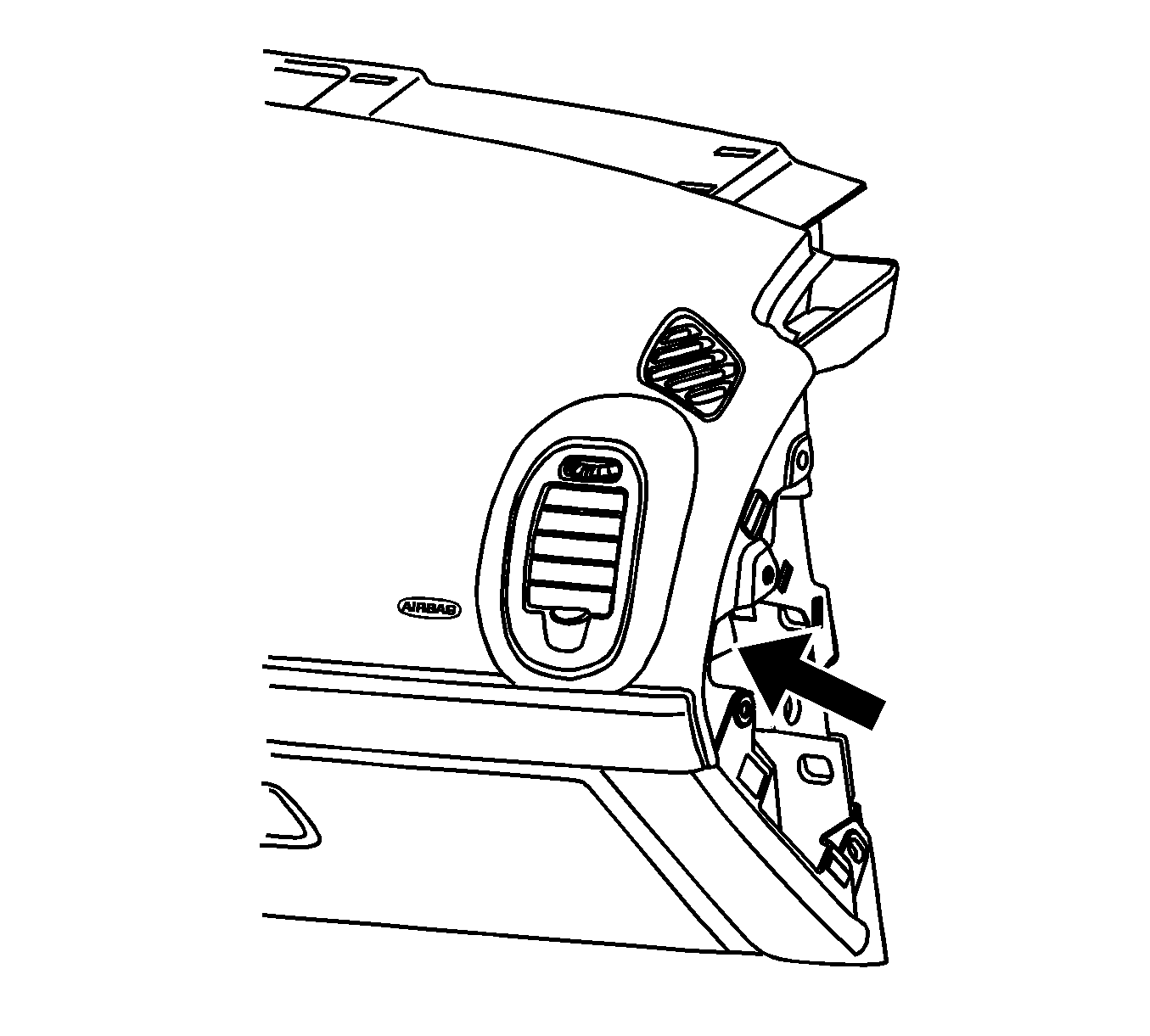
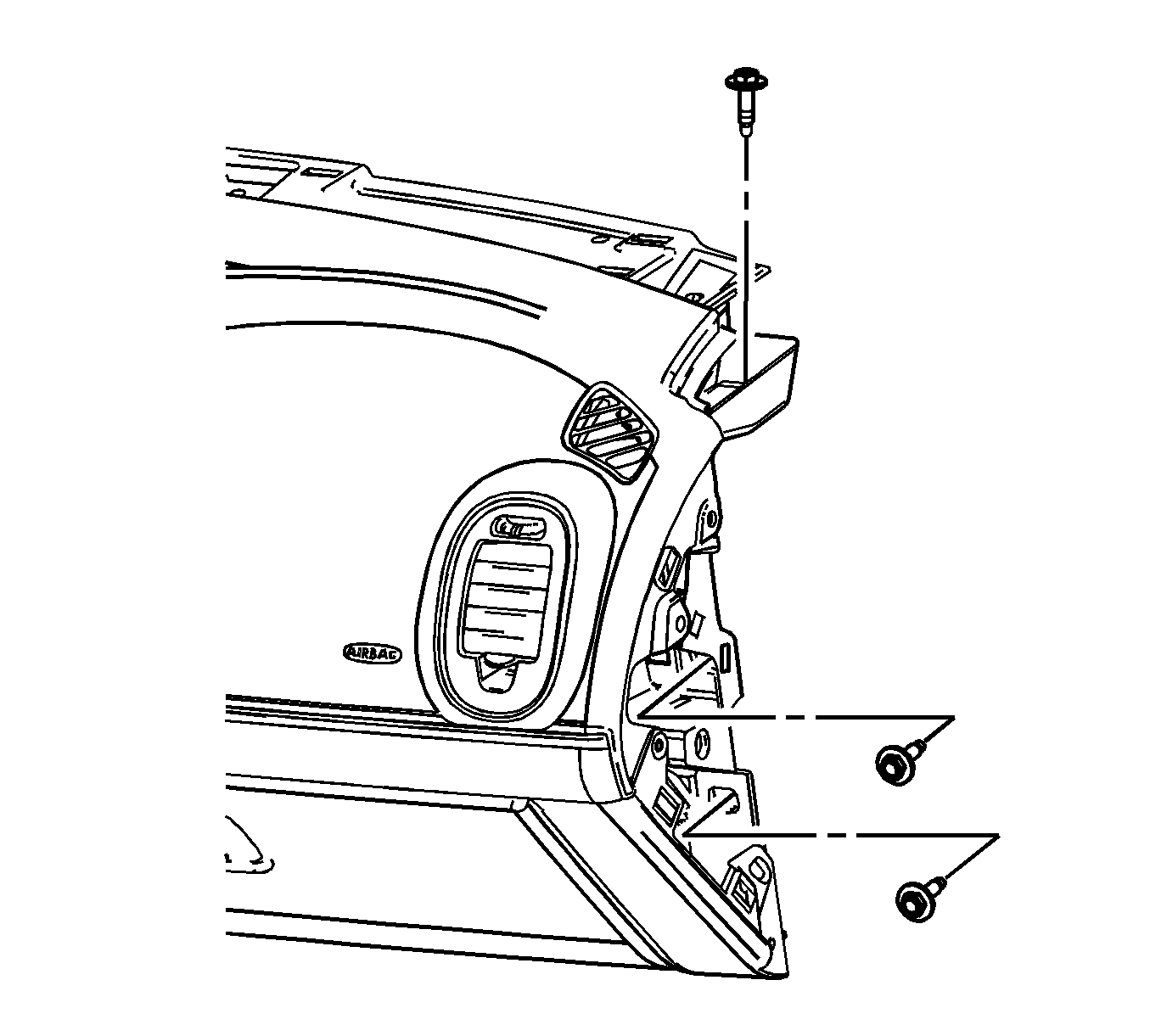
- Remove the I/P body RH bolts.
- Remove the right hand floor heater duct at the center floor heater duct. Refer to Rear Floor Air Outlet Duct Replacement - Right Side in Heating, Ventilation, and Air Conditioning.
- Remove the left hand floor heater duct at the center floor heater duct. Refer to Rear Floor Air Outlet Duct Replacement - Left Side in Heating, Ventilation, and Air Conditioning.
- Remove the I/P assembly.
- Remove and discard HVAC module drain seal and dash seal.
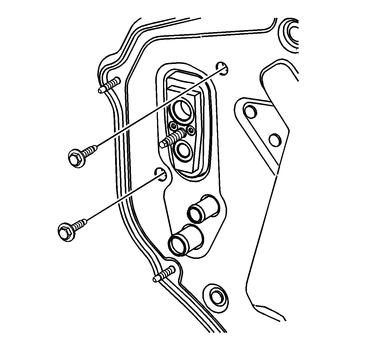
Important: Plug the heater core pipes and the TXV opening to prevent coolant or PAG oil from leaking into the interior.
Plug all A/C components immediately to prevent system contamination.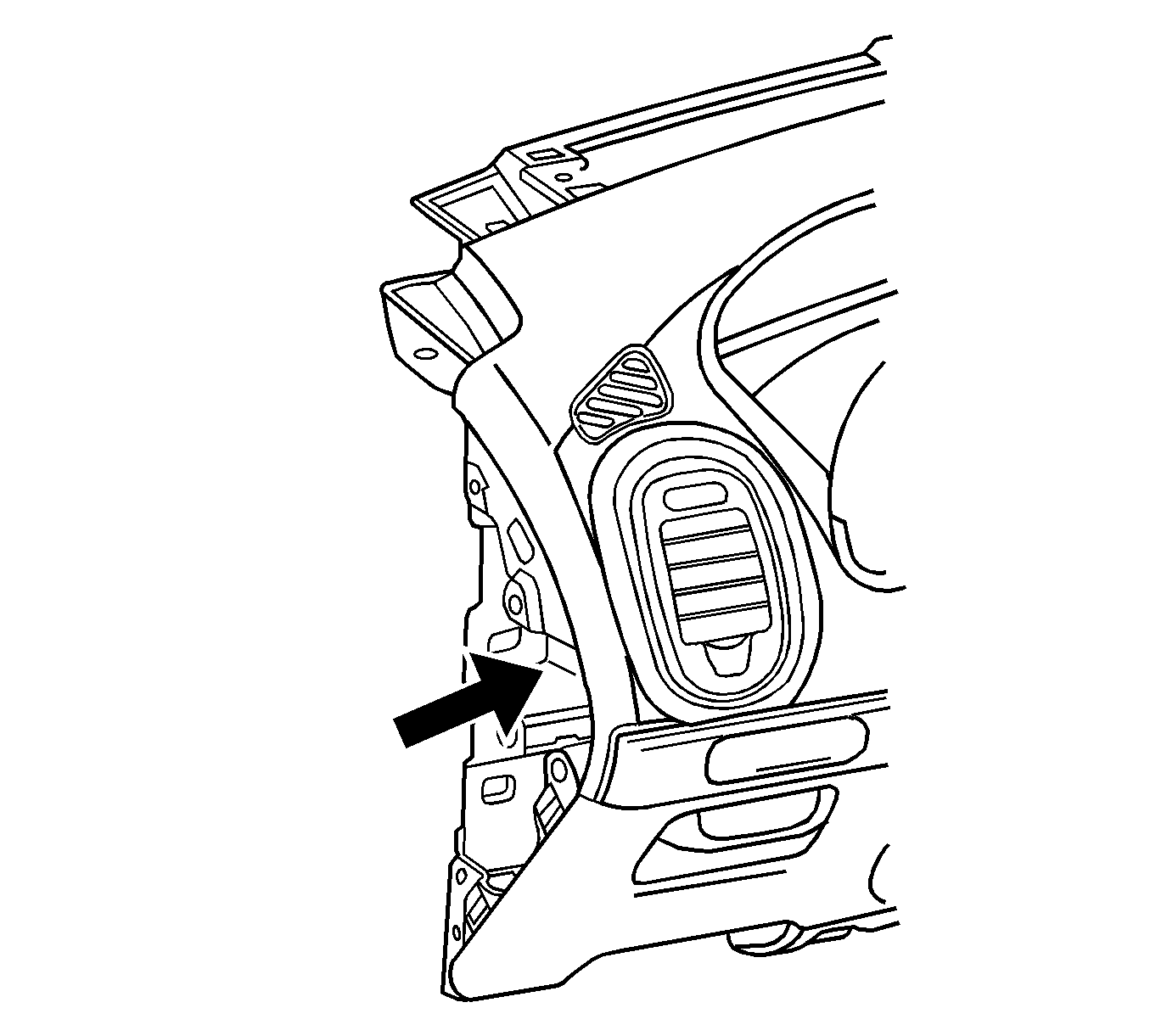
Installation Procedure
- Install new HVAC module drain seal and dash seal.
- Install the I/P assembly.
- Install the left hand floor heater duct at the center floor heater duct. Refer to Rear Floor Air Outlet Duct Replacement - Left Side in Heating, Ventilation, and Air Conditioning.
- Install the right hand floor heater duct at the center floor heater duct. Refer to Rear Floor Air Outlet Duct Replacement - Right Side in Heating, Ventilation, and Air Conditioning.
- Install the I/P body RH bolts.
- Install the I/P body LH bolts.
- Install the I/P upper trim panel. Refer to Instrument Panel Upper Trim Panel Replacement
- Install both windshield pillar garnish moldings. Refer to Windshield Pillar Garnish Molding Replacement in Interior Trim.
- Install the shifter assembly. Refer to Transmission Control Replacement in Automatic Transaxle - 4T40-E/4T45-E.
- Install the center support bracket floor bolts. Refer to Instrument Panel Center Support Bracket Replacement
- Install the BCM. Refer to Body Control Module Replacement in Computer/Integrating Systems.
- Install the brake pedal assembly. Refer to Brake Pedal Assembly Replacement in Hydraulic Brakes.
- Install the steering column assembly. Refer to Steering Column Replacement in Steering Wheel and Column.
- Install the steering column mounting bolts. Refer to Steering Column Replacement in Steering Wheel and Column.
- Install the stalk switches and the SIR coil connectors. Refer to Turn Signal Multifunction Switch Replacement in Steering Wheel and Column.
- Install the upper steering column shroud from the lower shroud. Refer to Steering Column Trim Covers Replacement in Steering Wheel and Column.
- Install the crush bracket to the front of dash plate nuts.
- Install the steering column to the I/P wire harness connector. Refer to Steering Column Replacement in Steering Wheel and Column.
- Install the accelerator pedal. Refer to Accelerator Pedal Replacement in Engine Controls - 2.2L.
- Install the knee bolster. Refer to Knee Bolster Replacement .
- Install the I/P to the body wire harness RH connectors.
- Install the I/P to the body wire harness and antenna LH connectors.
- Install both I/P outer trim panels. Refer to Instrument Panel Outer Trim Cover Replacement .
- Install the left closeout panel. Refer to Instrument Panel Insulator Panel Replacement - Left Side .
- Install the console. Refer to Console Replacement .
- Install the left console trim panel Refer to Front Floor Console Side Trim Panel Replacement - Left Side .
- Install the right console trim panel. Refer to Front Floor Console Side Trim Panel Replacement - Right Side .
- Install the HVAC module to the MOD plate bolts.
- Unplug A/C components.
- Install new sealing washers. Refer to Sealing Washer Replacement in Heating, Ventilation, and Air Conditioning.
- Install the liquid line at the TXV. Refer to Thermal Expansion Valve Replacement in Heating, Ventilation, and Air Conditioning.
- Install the suction hose at the TXV. Refer to Thermal Expansion Valve Replacement in Heating, Ventilation, and Air Conditioning.
- Evacuate and charge the refrigerant system. Refer to Refrigerant Recovery and Recharging in Heating, Ventilation, and Air Conditioning.
- Leak test the fittings using the J 39400-A
- Install the outlet heater hose at the heater core. Refer to Heater Outlet Hose Replacement in Heating, Ventilation, and Air Conditioning.
- Install the inlet heater hose at the heater core. Refer to Heater Inlet Hose Replacement in Heating, Ventilation, and Air Conditioning.
- Fill the coolant. Refer to Cooling System Draining and Filling in Engine Cooling.
- Connect the negative battery cable. Refer to Battery Negative Cable Disconnection and Connection in Engine Electrical.

Notice: Refer to Fastener Notice in the Preface section.

Tighten
Tighten the bolts to 26 N·m (19 lb ft).

Tighten
Tighten the bolts to 26 N·m (19 lb ft).
Tighten
Tighten the bolts to 10 N·m (89 lb in).

Tighten
Tighten the bolts to 10 N·m (89 lb in).


Tighten
Tighten the bolts to 4 N·m (35 lb in).
