For 1990-2009 cars only
Special Tools
J 45059 Angle Meter
Removal Procedure
- Disconnect the negative battery cable. Refer to Battery Negative Cable Disconnection and Connection.
- Remove the drive belt. Refer to Drive Belt Replacement.
- Remove the air cleaner inlet duct. Refer to Air Cleaner Inlet Duct Replacement.
- Remove the engine mount strut. Refer to Engine Mount Strut Replacement.
- Install the engine support fixture. Refer to Engine Support Fixture.
- Raise and support the vehicle. Refer to Lifting and Jacking the Vehicle.
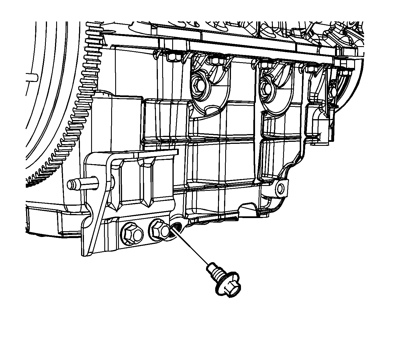
- Place a suitable drain pan under the oil pan drain plug.
- Remove the oil pan drain plug and drain the engine oil from the crankcase.
- Reinstall the oil pan drain plug and tighten.
- Remove the right front fender liner. Refer to Front Fender Liner Replacement.
- Remove the starter. Refer to Starter Motor Replacement.
- Remove the oil cooler. Refer to Engine Oil Cooler Replacement.
- Remove the oil filter adapter. Refer to Oil Filter Adapter and Bypass Valve Assembly Replacement.
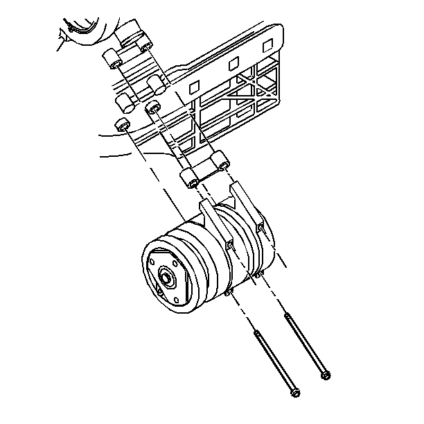
- Remove the air conditioning (A/C) compressor bolts and position the compressor aside.
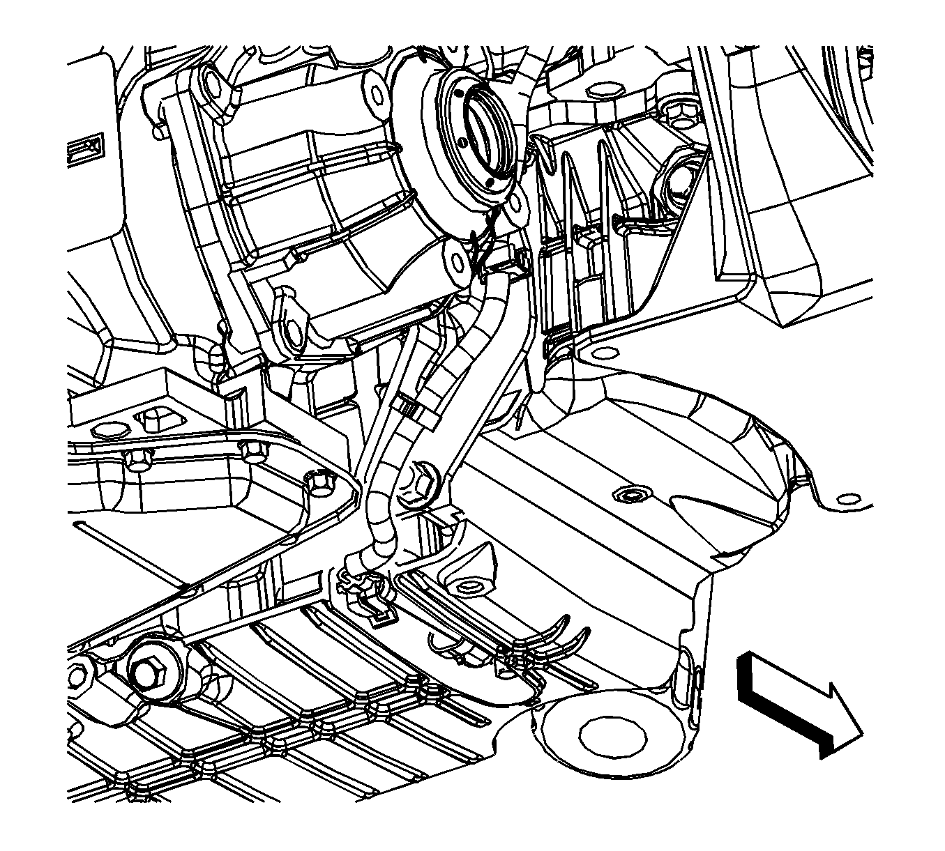
- Disconnect the oil level sensor electrical connector.
- Remove the catalytic converters. Refer to Catalytic Converter Replacement.
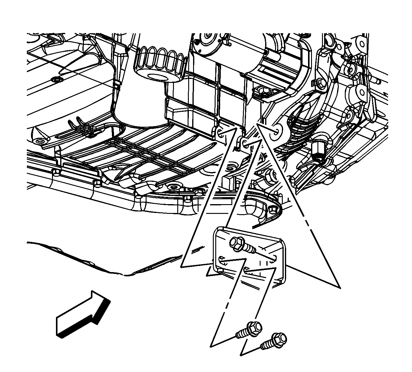
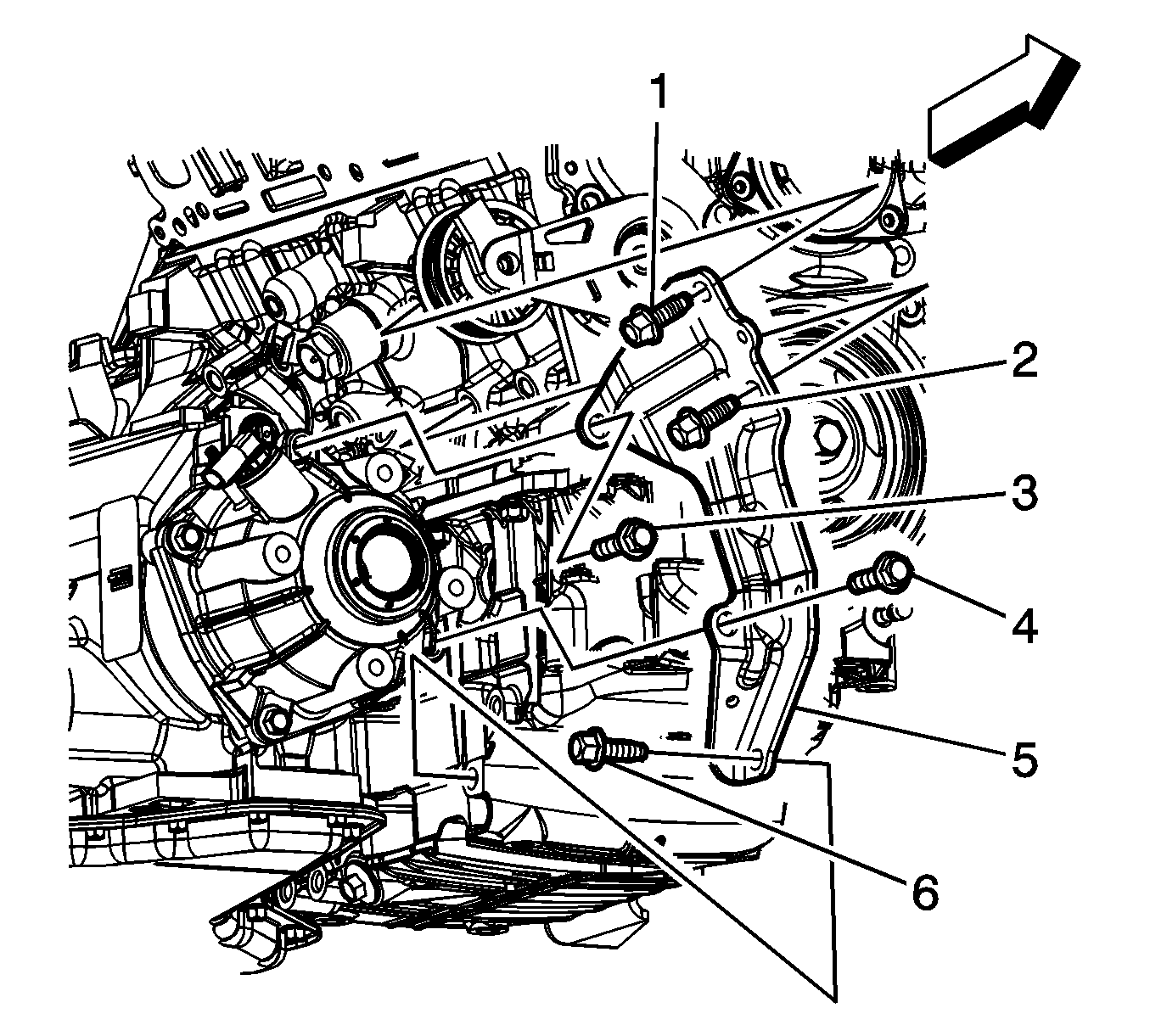
- Remove the transaxle brace to oil pan bolts.
- Remove the transaxle brace to transaxle bolt and remove the brace.
- Remove the transaxle brace to oil pan bolts, if equipped with regular production option (RPO) MT2.
- Remove the transaxle brace to transaxle bolt and remove the brace, if equipped with (RPO) MT2.
- Remove the transaxle brace to oil pan lower bolt (6), if equipped with (RPO) M15.
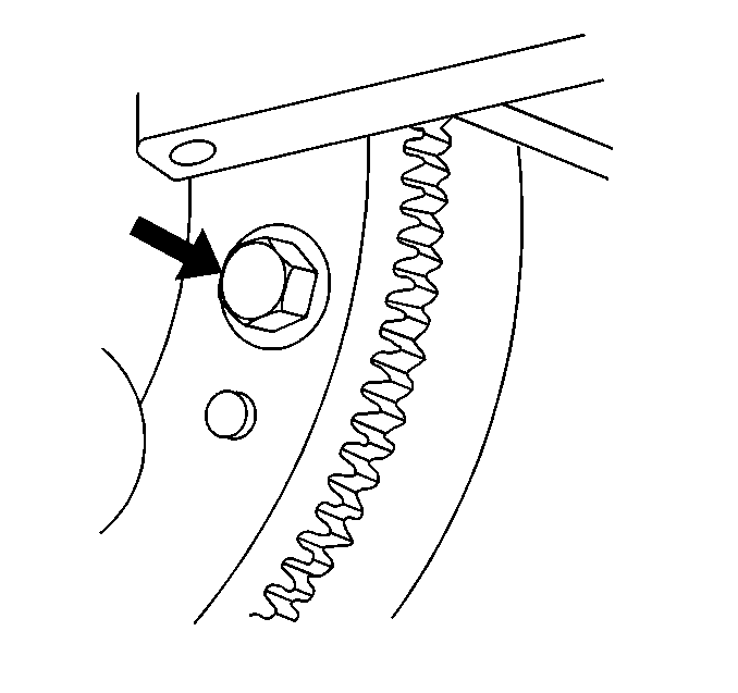
- Remove the flexplate to torque converter bolts.
- Lower the vehicle.
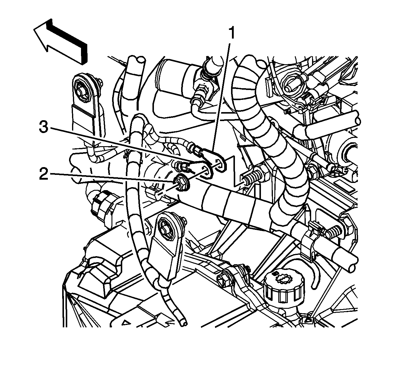
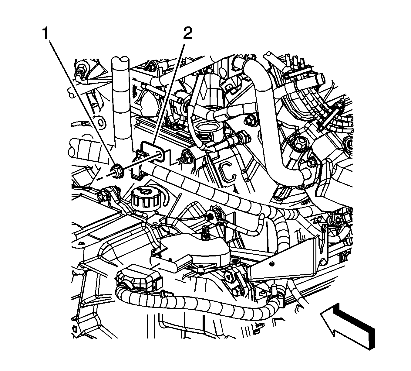
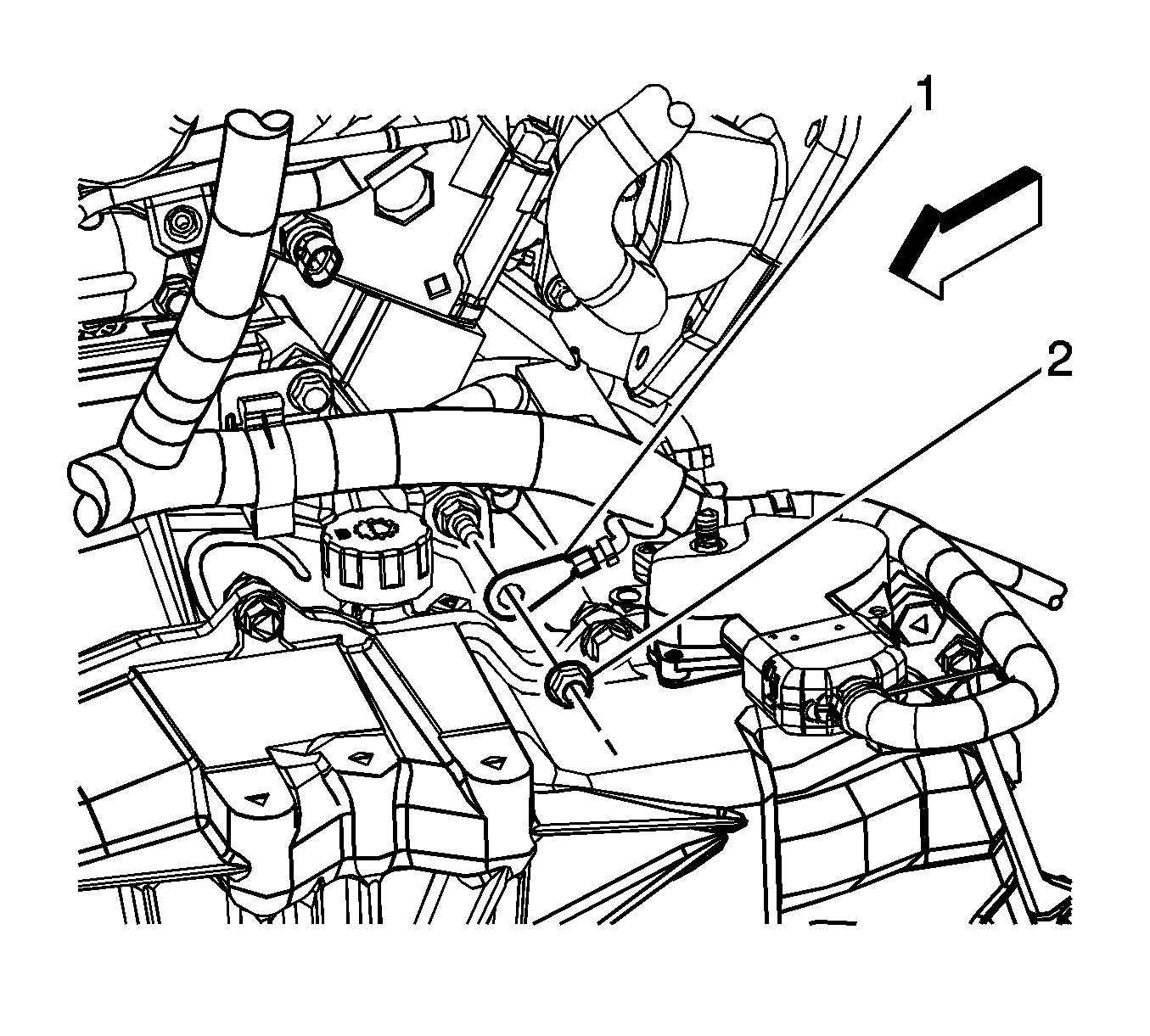
- Remove the engine harness ground nut (2) from the transaxle stud.
- Remove the engine wiring harness ground (3) and the negative battery cable ground (1) from the transaxle stud.
- Remove the engine wiring harness clip nut (1) from the transaxle stud.
- Remove the engine wiring harness clip (1) from the transaxle stud.
- Remove the engine wiring harness ground nut (2) from the transaxle stud.
- Remove the engine wiring harness ground (2) from the transaxle stud.
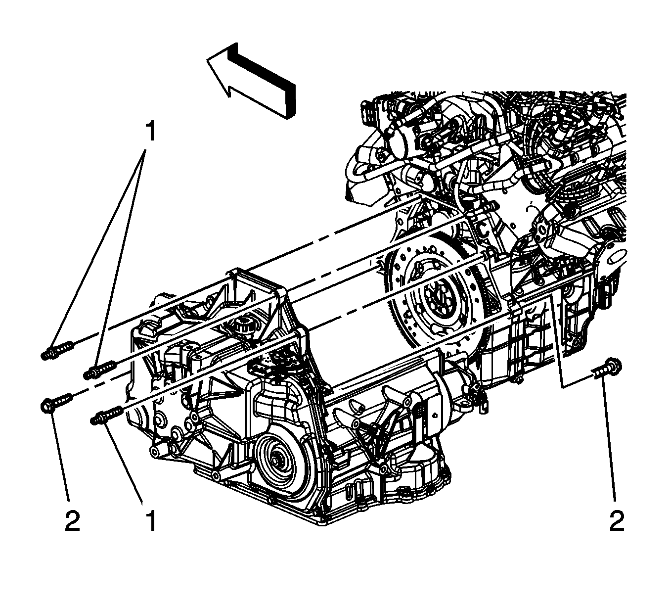
- Loosen, DO NOT REMOVE the transaxle studs (1) and bolts (2).
- Using the engine support fixture, raise the engine and transaxle slightly.
- Raise and support the vehicle.
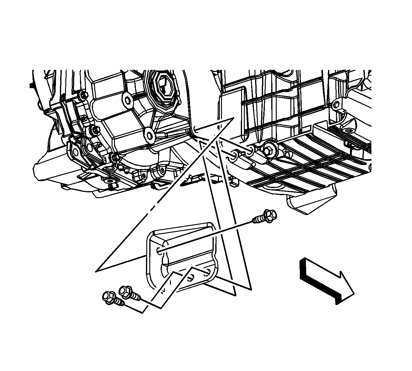
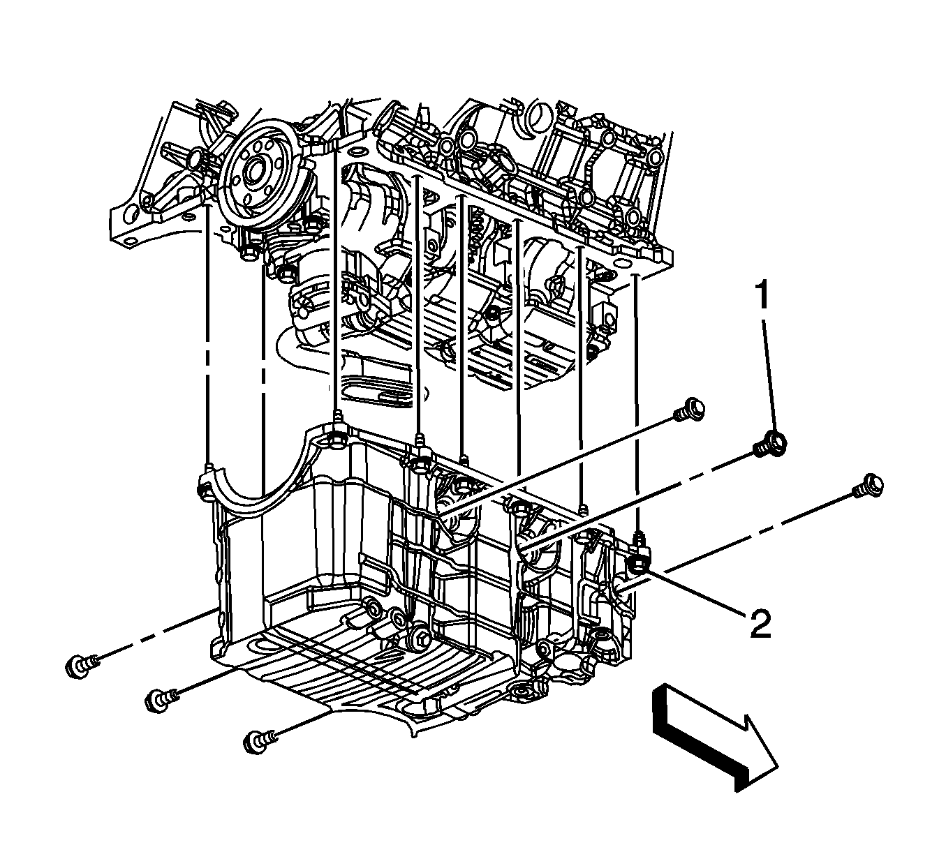
- Remove the oil pan bolts (1 and 2).
- Separate the engine and transaxle approximately 13 mm (1/2 in).
- Ensure that when removing the oil pan, the pan clears the boss (1) on the transaxle.
- Remove the oil pan, if the pan cannot be removed, lower the vehicle and perform steps 25 and 27 again until the pan can be removed.
- Remove and discard the oil pan gasket.
- Clean the oil pan sealing surfaces.
Notice: Refer to Component Fastener Tightening Notice in the Preface section.
Tighten
Tighten the oil pan drain plug to 25 N·m (18 lb ft).
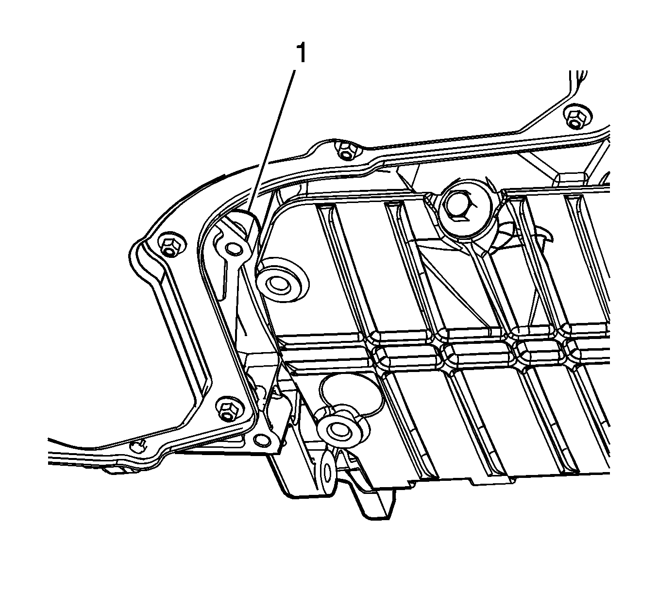
Installation Procedure
- Apply sealer to both sides of the crankshaft rear main bearing cap. Press the sealer into the gap using a putty knife. Refer to Adhesives, Fluids, Lubricants, and Sealers.
- Apply sealer to both sides of the front cover/block mating area. Refer to Adhesives, Fluids, Lubricants, and Sealers.
- Install a NEW oil pan gasket.
- Position the oil pan to the engine.
- Install the oil pan bolts (1 and 2).
- Lower the vehicle.
- Using the engine support fixture, lower the engine and transaxle.
- Tighten the transaxle studs (1) and bolts (2).
- Install the engine wiring harness ground (1) to the transaxle stud.
- Install the engine wiring harness ground nut (2) to the transaxle stud.
- Install the engine wiring harness clip (2) to the transaxle stud.
- Install the engine wiring harness clip nut (1) to the transaxle stud.
- Install the negative battery cable ground (1) and the engine wiring harness ground (3) to the transaxle stud.
- Install the engine harness ground nut (2) to the transaxle stud.
- Raise and support the vehicle.
- Install the flexplate-to-torque converter bolts.
- Install the transaxle brace to oil pan lower bolt (6), if equipped with (RPO) M15.
- Position the transaxle brace and install the transaxle brace to transaxle bolt until snug, if equipped with (RPO) MT2.
- Install the transaxle brace to oil pan bolts, if equipped with (RPO) MT2.
- Position the transaxle brace and install the transaxle brace to transaxle bolt until snug.
- Install the transaxle brace to oil pan bolts.
- Connect the oil level sensor electrical connector.
- Install the catalytic converters. Refer to Catalytic Converter Replacement.
- Position the A/C compressor and install the bolts.
- Install the right front fender liner. Refer to Front Fender Liner Replacement.
- Install the starter. Refer to Starter Motor Replacement.
- Install the oil filter adapter. Refer to Oil Filter Adapter and Bypass Valve Assembly Replacement.
- Install the oil cooler. Refer to Engine Oil Cooler Replacement.
- Ensure that the oil pan drain plug is tighten.
- Lower the vehicle.
- Remove the engine support fixture.
- Install the engine mount strut. Refer to Engine Mount Strut Replacement.
- Install the air cleaner inlet duct. Refer to Air Cleaner Inlet Duct Replacement.
- Install the drive belt. Refer to Drive Belt Replacement.
- Fill the crankcase.
- Connect the negative battery cable. Refer to Battery Negative Cable Disconnection and Connection.

Notice: Refer to Fastener Notice in the Preface section.
Tighten
| • | Tighten the bolts (1) to 50 N·m (37 lb ft). |
| • | Tighten the bolts (2) to 25 N·m (18 lb ft). |

Tighten
Tighten the bolts/studs to 90 N·m (66 lb ft).

Tighten
Tighten the nut to 25 N·m (18 lb ft).

Tighten
Tighten the nut to 25 N·m (18 lb ft).

Tighten
Tighten the nut to 25 N·m (18 lb ft).

Tighten
Tighten the bolts to 62 N·m (46 lb ft).

Tighten
Tighten the bolts to 50 N·m (37 lb ft).

Tighten
Tighten the bolts to 50 N·m (37 lb ft).

Tighten
Tighten the bolts to 50 N·m (37 lb ft).


Tighten
Tighten the bolts to 50 N·m (37 lb ft).
Tighten
Tighten the drain plug to 25 N·m (18 lb ft).
