For 1990-2009 cars only
Stabilizer Shaft Replacement Base Sedan
Removal Procedure
- Raise and support the vehicle. Refer to Lifting and Jacking the Vehicle .
- Scribe a line on the rear camber adjust bolts (both left and right).
- Remove the toe link. Refer to Toe Link Replacement .
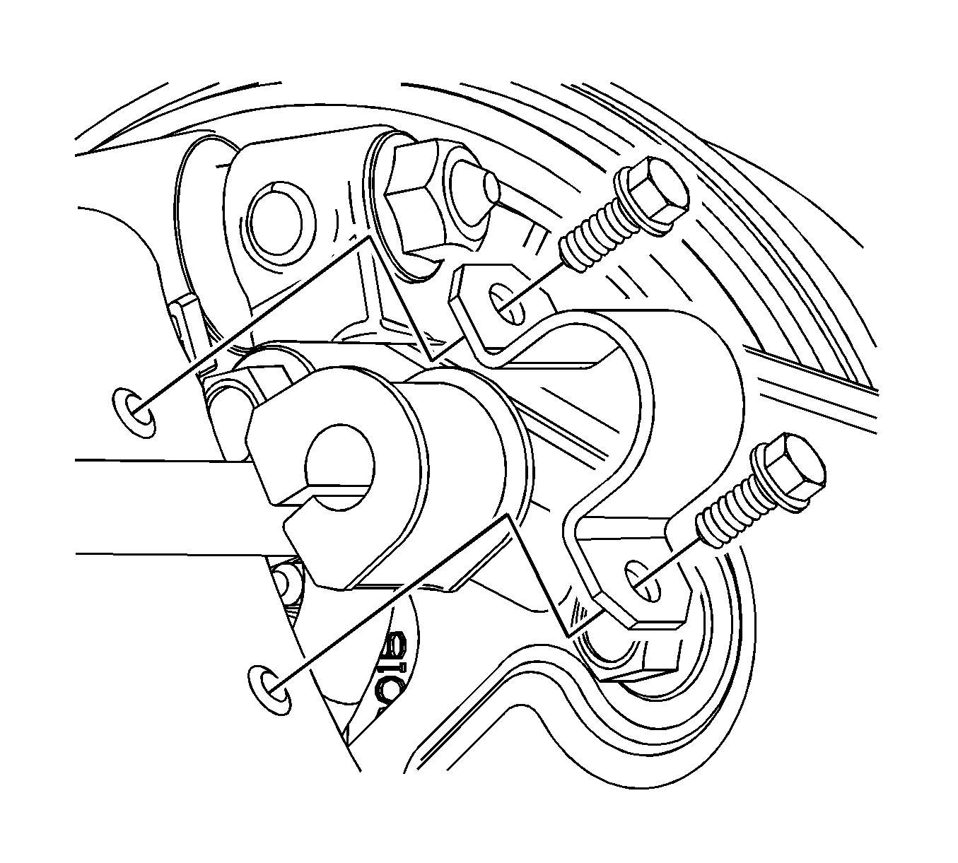
- Remove the stabilizer shaft bracket bolts.
- Remove the stabilizer shaft insulators from the stabilizer shaft.
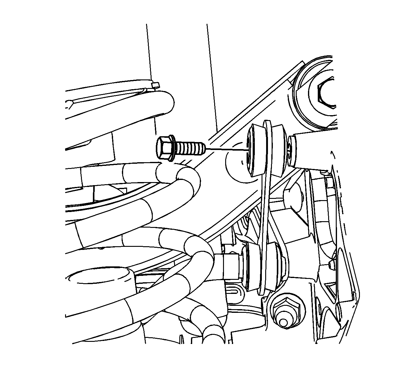
- Remove the stabilizer link to knuckle bolts.
- Remove the stabilizer shaft.


Installation Procedure
- Install the stabilizer shaft.
- Install the stabilizer shaft insulators.
- Install the stabilizer shaft brackets.
- Install the stabilizer shaft bracket bolts.
- Install the stabilizer shaft links to knuckle bolts.
- Install the toe link. Refer to Toe Link Replacement .
- Lower the vehicle.

Notice: Refer to Fastener Notice in the Preface section.
Tighten
Tighten the stabilizer shaft insulator bracket retaining bolts to 35 N·m (26 lb ft).

Tighten
Tighten the bolts to 55 N·m (41 lb ft).
Stabilizer Shaft Replacement Extended Sedan
Removal Procedure
- Raise and support the vehicle. Refer to Lifting and Jacking the Vehicle .
- Remove the rear tire and wheel assemblies. Refer to Tire and Wheel Removal and Installation .
- Remove the muffler assembly. Refer to Muffler Replacement .
- Disconnect the fuel pump module electrical connector from the underbody wiring harness.
- Disconnect the evaporative emission (EVAP) vent valve solenoid harness electrical connector from the underbody wiring harness.
- Suitably support the gas tank.
- Remove the front fuel tank strap bolts.
- Lower the fuel tank as necessary for access.
- Place a index mark on the rear camber adjusting bolts.
- Suitably support the rear control arms.
- Remove the right and left toe links. Refer to Toe Link Replacement .
- Remove the stabilizer shaft bracket bolts.
- Remove the stabilizer shaft insulators from the stabilizer shaft.
- Remove the stabilizer link to knuckle bolts.
- Remove the stabilizer shaft.


Installation Procedure
- Install the stabilizer shaft.
- Install the stabilizer shaft insulators.
- Install the stabilizer shaft brackets.
- Install the stabilizer shaft bracket bolts.
- Install the stabilizer shaft links to knuckle bolts.
- Install the right and left toe links. Line up index marks on the camber bolts. Refer to Toe Link Replacement .
- Remove the supports from the rear control arms.
- Raise the fuel tank into position.
- Install the front fuel tank strap bolts.
- Remove support from the fuel tank.
- Connect the EVAP vent valve solenoid harness electrical connector to the underbody wiring harness.
- Connect the fuel pump module electrical connector to the underbody wiring harness.
- Install the muffler assembly. Refer to Muffler Replacement .
- Install the rear tire and wheel assemblies. Refer to Tire and Wheel Removal and Installation .
- Lower the vehicle.

Notice: Refer to Fastener Notice in the Preface section.
Tighten
Tighten the stabilizer shaft insulator bracket retaining bolts to 35 N·m (26 lb ft).

Tighten
Tighten the bolts to 55 N·m (41 lb ft).
Tighten
Tighten the bolts to 20 N·m (15 lb ft).
