Brake Fluid Level Indicator Switch Replacement Without RPO LAT
Caution: Refer to Brake Fluid Irritant Caution in the Preface section.
Notice: Refer to Brake Fluid Effects on Paint and Electrical Components Notice in the Preface section.
Removal Procedure
- Disconnect the brake fluid level indicator switch electrical connector.
- Remove and discard the brake fluid from the master cylinder reservoir.
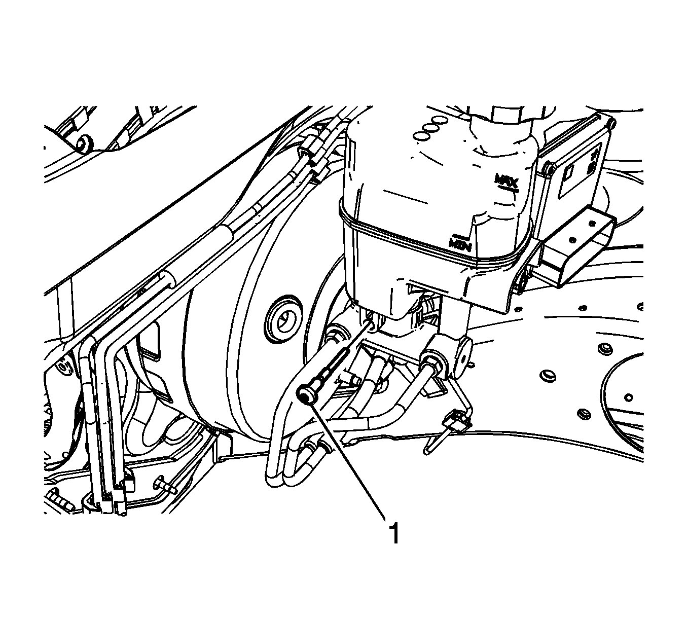
- Remove the master cylinder reservoir bolt (1).
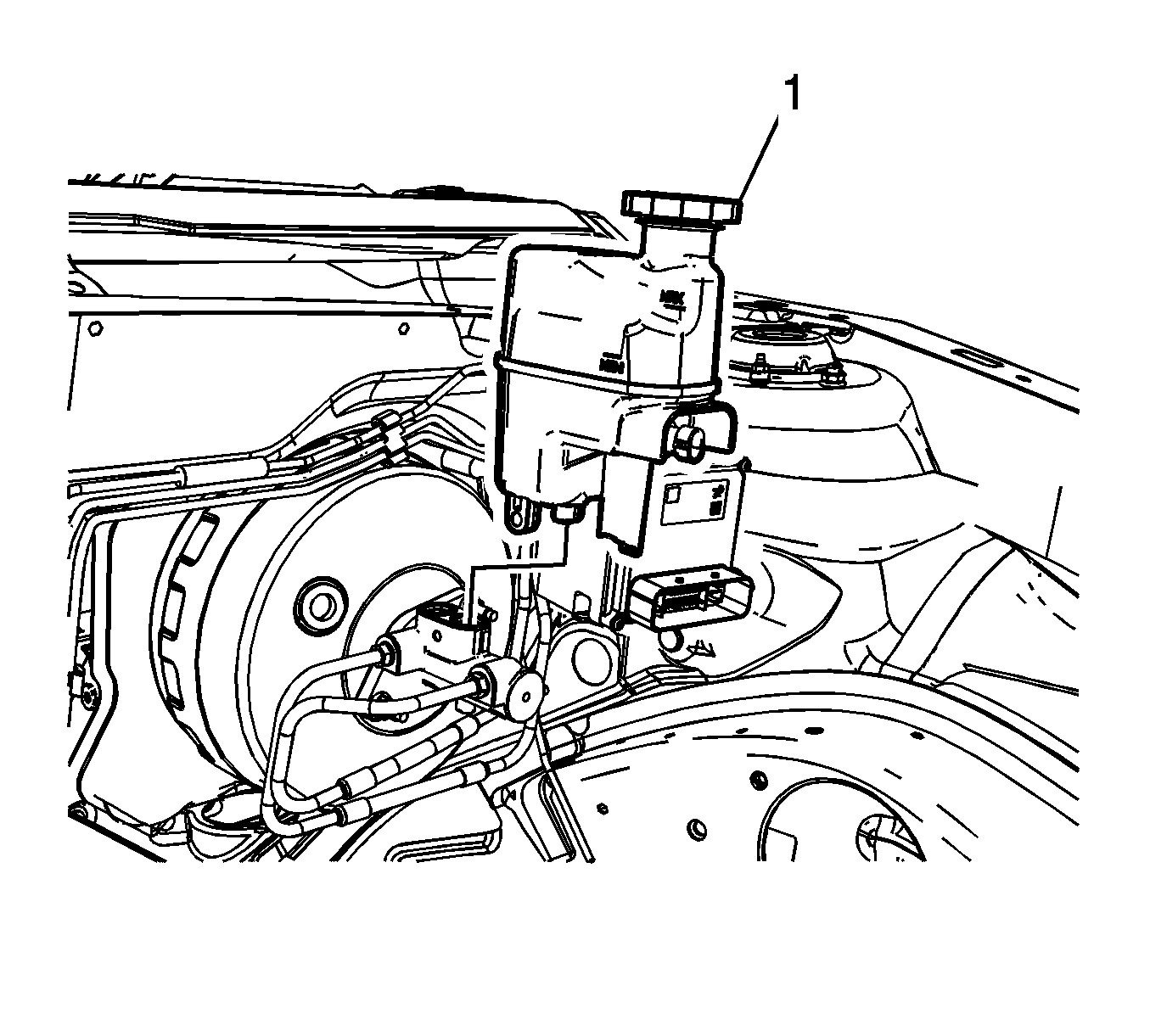
- Remove the reservoir (1) from the master cylinder.
- Remove the fluid level indicator switch (1) from the master cylinder.
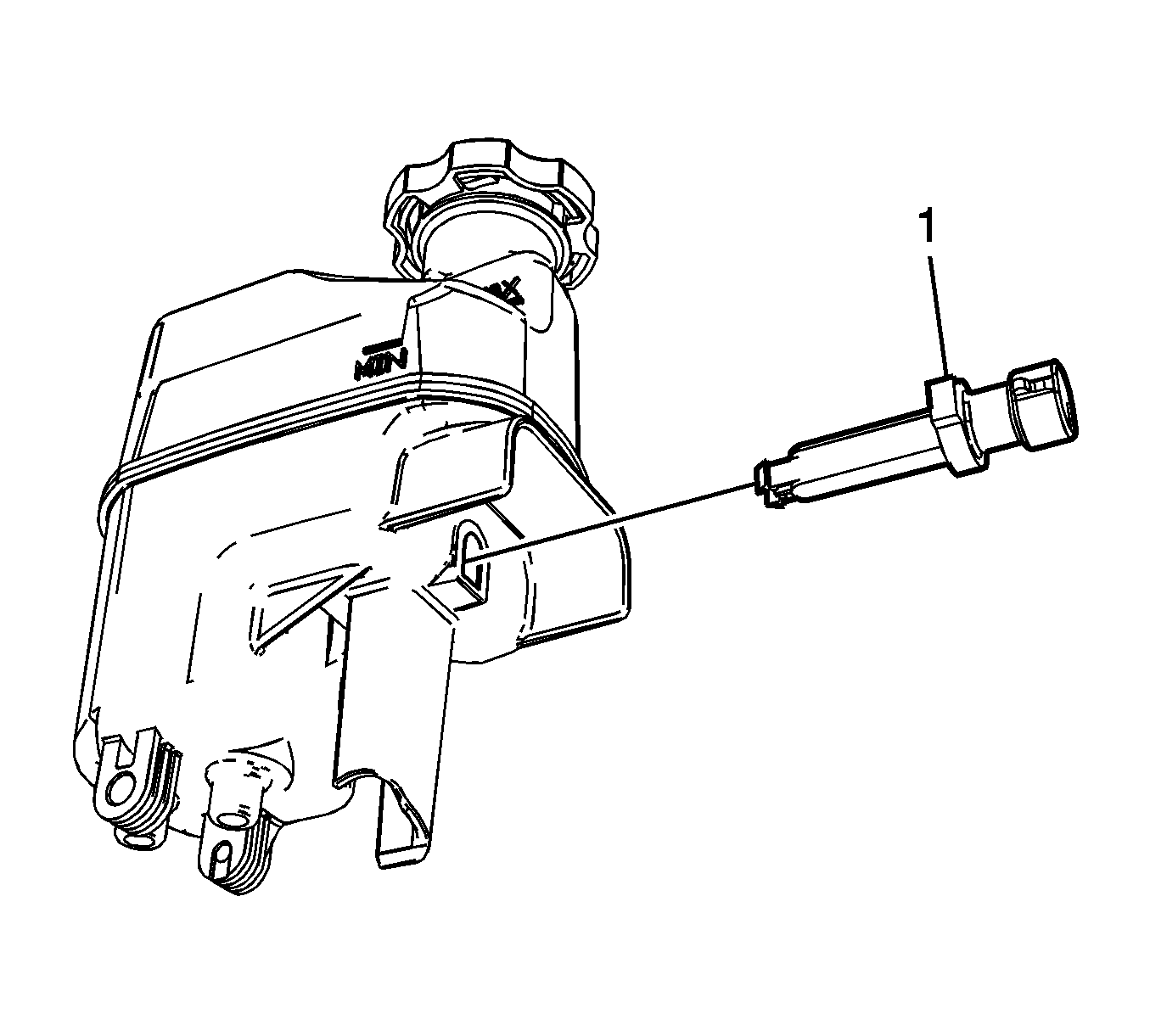
Compress the locking tabs on the switch from the underside of the master cylinder reservoir.
Installation Procedure
- Clean the reservoir with denatured alcohol.
- Dry the reservoir with filtered, non-lubricated compressed air.
- Install the fluid level indicator switch (1) to the master cylinder.
- Install the reservoir (1) to the master cylinder.
- Install the master cylinder reservoir bolt (1).
- Connect the brake fluid level indicator switch electrical connector.
- Fill the master cylinder reservoir. Refer to Master Cylinder Reservoir Filling.

Ensure the locking tabs on the switch are fully engaged to the master cylinder reservoir.

Notice: Refer to Fastener Notice in the Preface section.

Tighten
Tighten the bolt to 8 N·m (71 lb in).
Brake Fluid Level Indicator Switch Replacement With RPO LAT
Caution: Refer to Brake Fluid Irritant Caution in the Preface section.
Notice: Refer to Brake Fluid Effects on Paint and Electrical Components Notice in the Preface section.
Removal Procedure
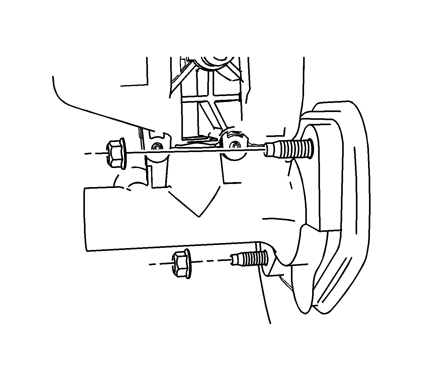
- Remove the brake master cylinder mounting nuts from the booster and position the master cylinder to gain access to the brake fluid level sensor but do not disconnect the brake lines. Refer to Master Cylinder Replacement .
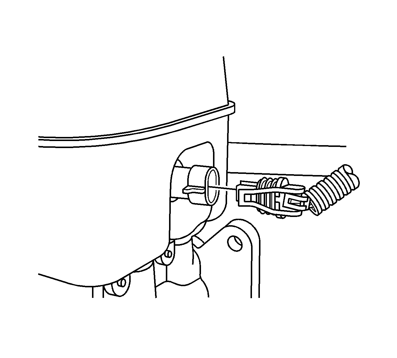
- Disconnect the electrical connector from the brake fluid level sensor.
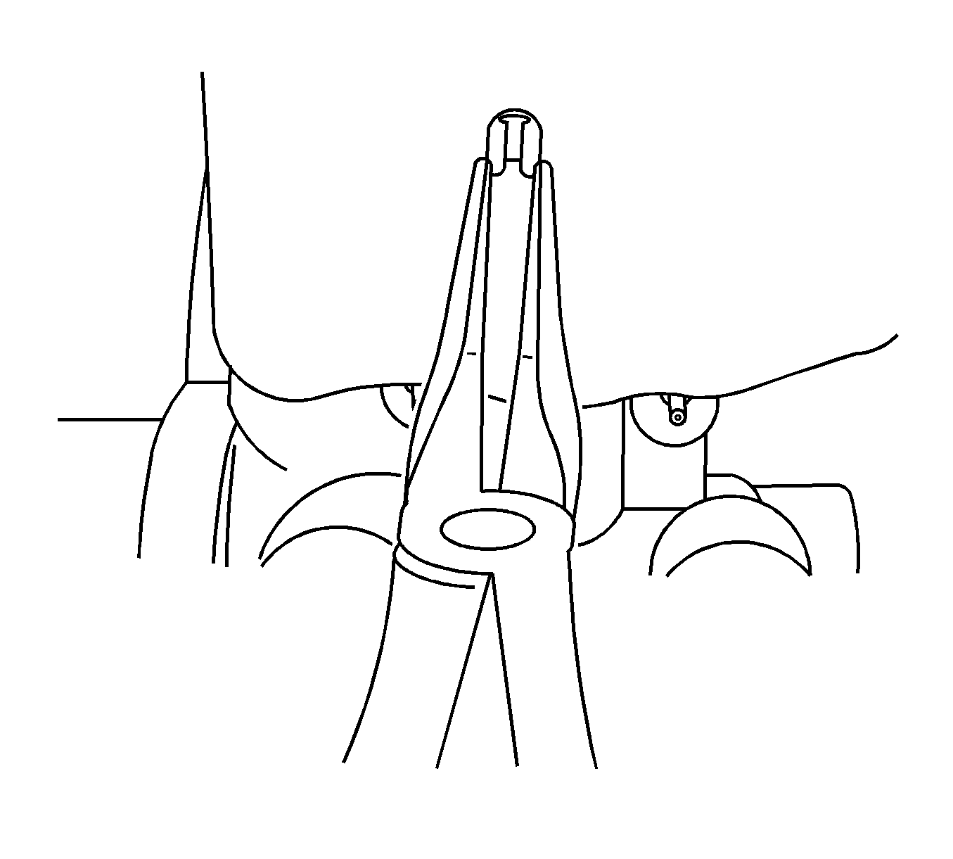
- Using needle nose pliers carefully depress the retaining tabs on the end of the brake fluid level sensor.
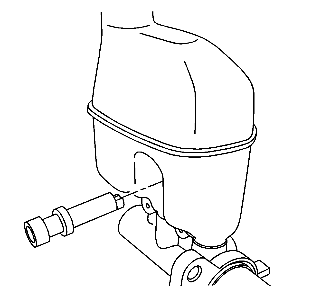
- Remove the brake fluid level sensor from the master cylinder.
Installation Procedure
- Align the brake fluid level sensor to the master cylinder reservoir.
- Press the brake fluid level sensor into the master cylinder reservoir, ensure the retaining tabs click into place.
- Connect the electrical connector to the brake fluid level sensor.
- Install the brake master cylinder to the booster assembly. Refer to Master Cylinder Replacement .


Important: Ensure the gasket on the outside barrel of the master cylinder is positioned properly and is free of cuts and tears.
