Tools Required
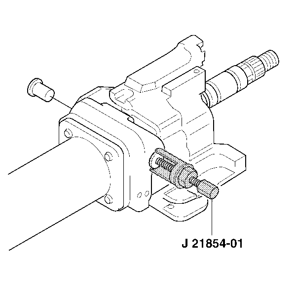
J 21854-01 Pivot Pin Remover
Removal Procedure
- Disable the SIR system. Refer to SIR Disabling and Enabling in SIR.
- Remove the turn signal and multifunction switch assembly. Refer to Turn Signal Multifunction Switch Replacement .
- Remove the steering column tilt head components. Refer to Steering Column Tilt Head Replacement .
- If column shift, remove the shift lever. Refer to Shift Lever Replacement .
- Remove the tilt spring assembly. Refer to Steering Column Tilt Spring Replacement .
- If column shift, remove the linear shift assembly. Refer to Linear Shift Assembly Replacement .
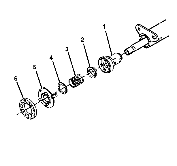
- Remove the steering shaft seal (6).
- Remove the sensor retainer (5).
- Remove the lower spring retainer (4).
- Remove the lower bearing spring (3).
- Remove the lower bearing seat (2).
- Remove the adapter and bearing assembly (1).
- Remove the 2 pivot pins from the steering column support assembly with J 21854-01 .
- Install the tilt lever and tilt the column to the upright position.
- Remove the upper tilt head assembly with the steering shaft assembly.
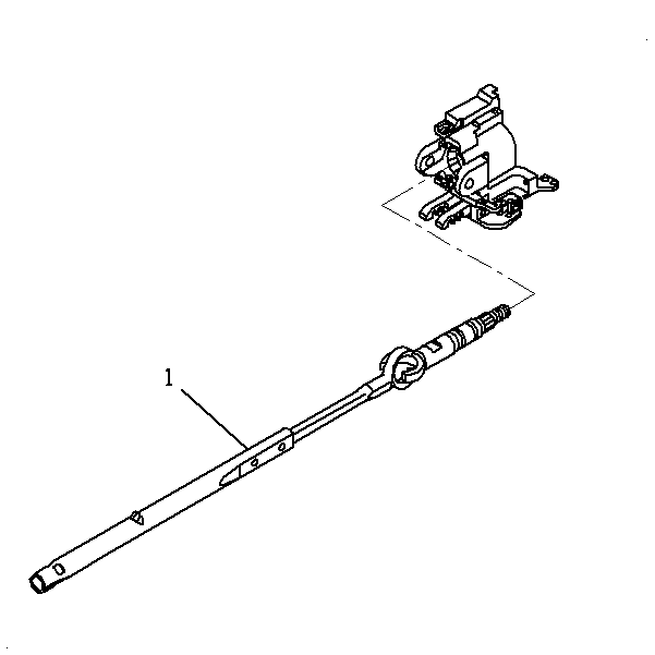
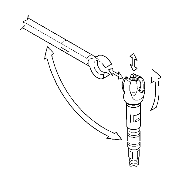
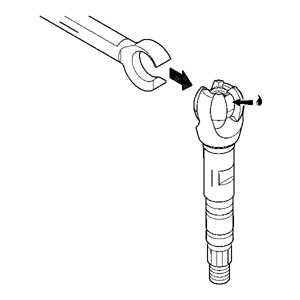
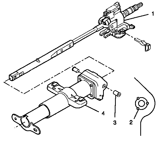
- Remove the steering shaft assembly (1).
- Tilt the race and upper shaft assembly 90 degrees to the lower steering shaft assembly and disengage.
- Remove the 4 TORX® head screws (2) and discard from the steering column support assembly (1).
Caution: Refer to SIR Caution in the Preface section.
Important: Mark the race and upper shaft assembly and the lower steering shaft assembly to ensure proper assembly. Failure to assemble properly will cause the steering wheel to be turned 180 degrees.
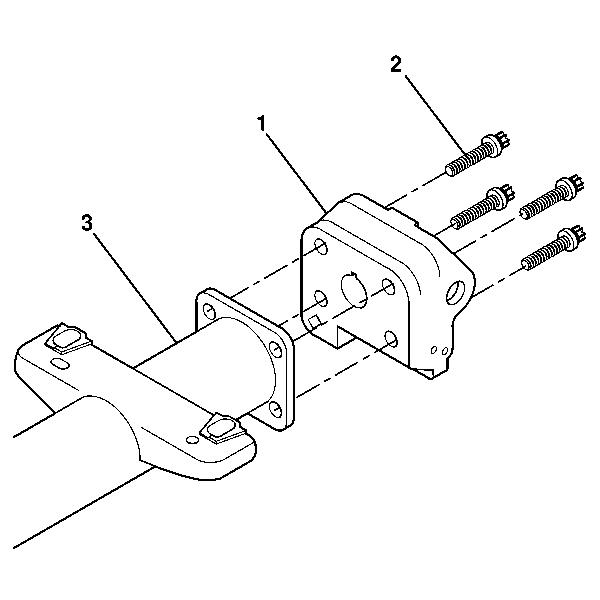
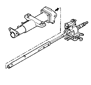
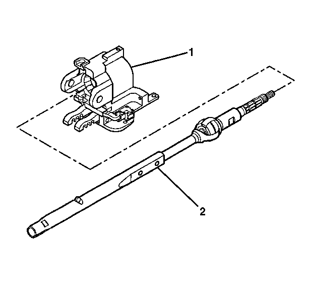
Remove the steering column support assembly (1) from the steering column jacket (3).
Installation Procedure
- Install the steering column support assembly (1) to the steering column jacket assembly (3).
- Install the 4 TORX® screws (2).
- Lubricate the exposed centering sphere with GM P/N 12345718 (Canadian P/N 10953516).
- Install the lower steering shaft assembly to the race and upper shaft assembly
- Install the steering shaft assembly (2) into the steering column tilt head assembly (1).
- Install the steering column tilt head assembly (1) to the steering column jacket assembly (4).
- Lubricate the 2 pivot pins (3) with GM P/N 12346293 (Canadian P/N 992723).
- Install the 2 pivot pins (3).
- Stake the pivot pin locations (2).
- Install the adapter and bearing assembly (1).
- Install the lower bearing seat (2).
- Install the lower bearing spring (3).
- Install the lower spring retainer (4).
- Install the sensor retainer (5).
- Install the steering shaft seal (6).
- If column shift, install the linear shift assembly. Refer to Linear Shift Assembly Replacement .
- Install the tilt spring. Refer to Steering Column Tilt Spring Replacement .
- If column shift, install the shift lever. Refer to Shift Lever Replacement .
- Install the steering column tilt head components. Do not install the trim covers until the turn signal and multifuction switch assembly has been installed. Refer to Steering Column Tilt Head Replacement .
- Install the turn signal and multifunction switch assembly. Refer to Turn Signal Multifunction Switch Replacement .
- Enable the SIR system. Refer to SIR Disabling and Enabling in SIR.
Important: Once the steering column support and the pivot pins have been staked 3 times, replace the steering column support.
Notice: Refer to Fastener Notice in the Preface section.
Tighten
Tighten the screws to 17 N·m (13 lb ft).
Important: Use the alignment marks from the disassemble procedure to install the lower steering shaft and the race and upper shaft assembly. Failure to assemble properly will cause the steering wheel to be turned 180 degrees.
Important: Once the steering column support and the pivot pins have been staked 3 times, replace the steering column support.
Caution: Improper routing of the wire harness assembly may damage the inflatable restraint steering wheel module coil. This may result in a malfunction of the coil, which may cause personal injury.
