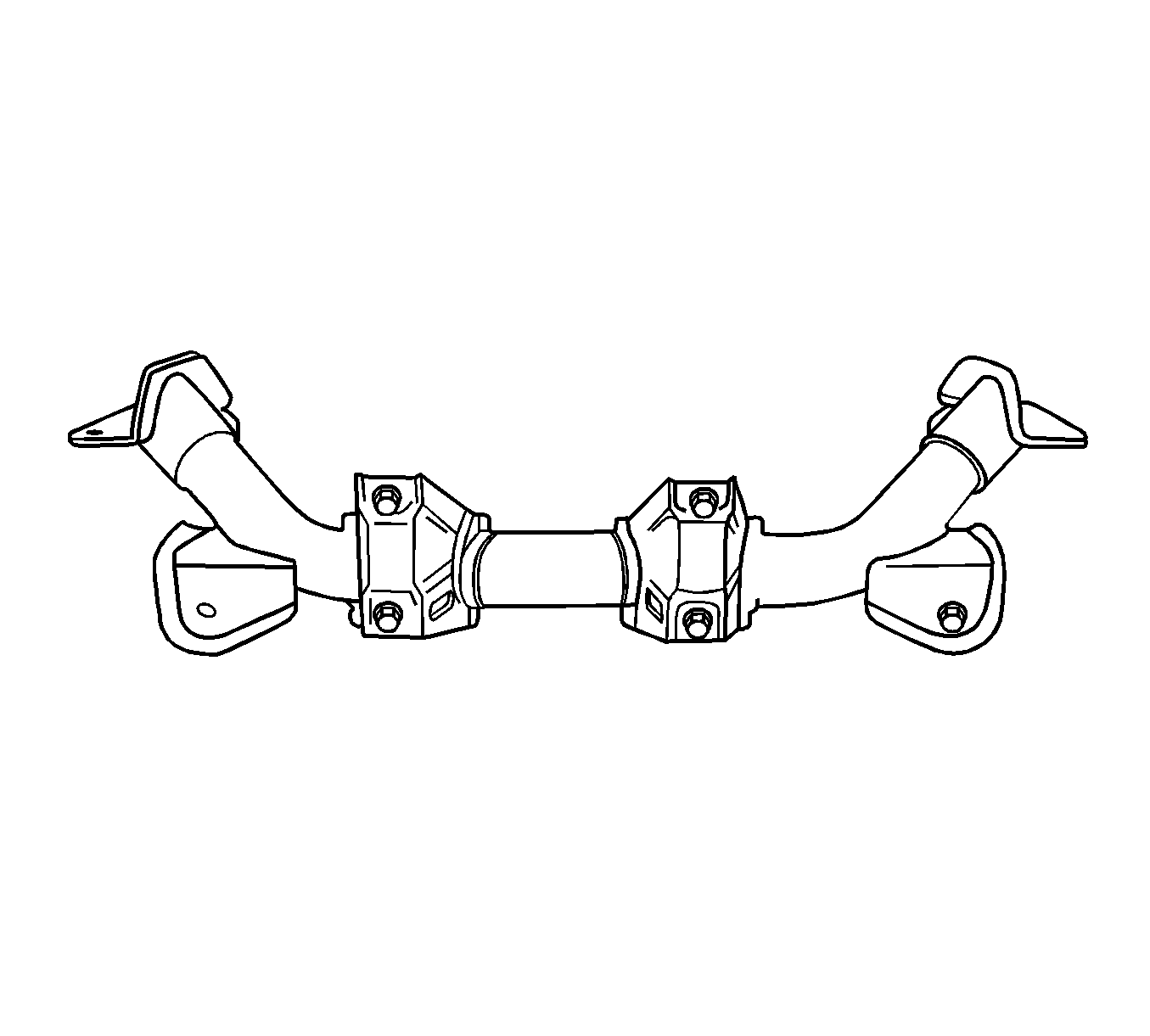
For 1990-2009 cars only
Removal Procedure
- Raise the vehicle. Refer to Lifting and Jacking the Vehicle.
- Remove the wheel. Refer to Tire and Wheel Removal and Installation.
- Remove the stabilizer bar and the stabilizer bar ball pin subassembly. Refer to Stabilizer Shaft Replacement.
- Remove the swing arm and the ball pin assembly. Refer to Lower Control Arm Replacement.
- Remove the steering gear mounting bracket bolt, and remove the gasket and the steering gear mounting bracket.
- Remove the nut connecting the fore axle welded unit to the front crossbeam. Carefully support the fore axle welded unit to avoid falling down.
- Remove the fore axle welded unit.

Installation Procedure
- Support the fore axle welded unit and install the bolt connecting the fore axle welded unit to the front crossbeam.
- Install the steering gear mounting bracket and gasket, and tighten the steering gear mounting bracket bolts to the specified torque.
- Install the swing arm and the ball pin assembly. Refer to Lower Control Arm Replacement.
- Install the wheel and lower the vehicle.
Caution: Refer to Fastener Caution in the Preface section.

Tighten
Tighten the fore axle welded unit to the front crossbeam connecting bolt to 68-97 N·m.
Tighten
Tighten the steering gear mounting bracket bolts to 31-48 N·m.
