Oil Temperature, Oil Pressure, and Voltmeter Gage Replacement CSV SWBHSV VXR8
Removal Procedure
- Disconnect the battery negative cable from the battery. Refer to Battery Negative Cable Disconnection and Connection.
- Remove the SIC from the I/P. Refer to Secondary Driver Information Display Replacement.
- Remove the ESC switch from the SIC housing. Refer to Electronic Suspension Switch Replacement.
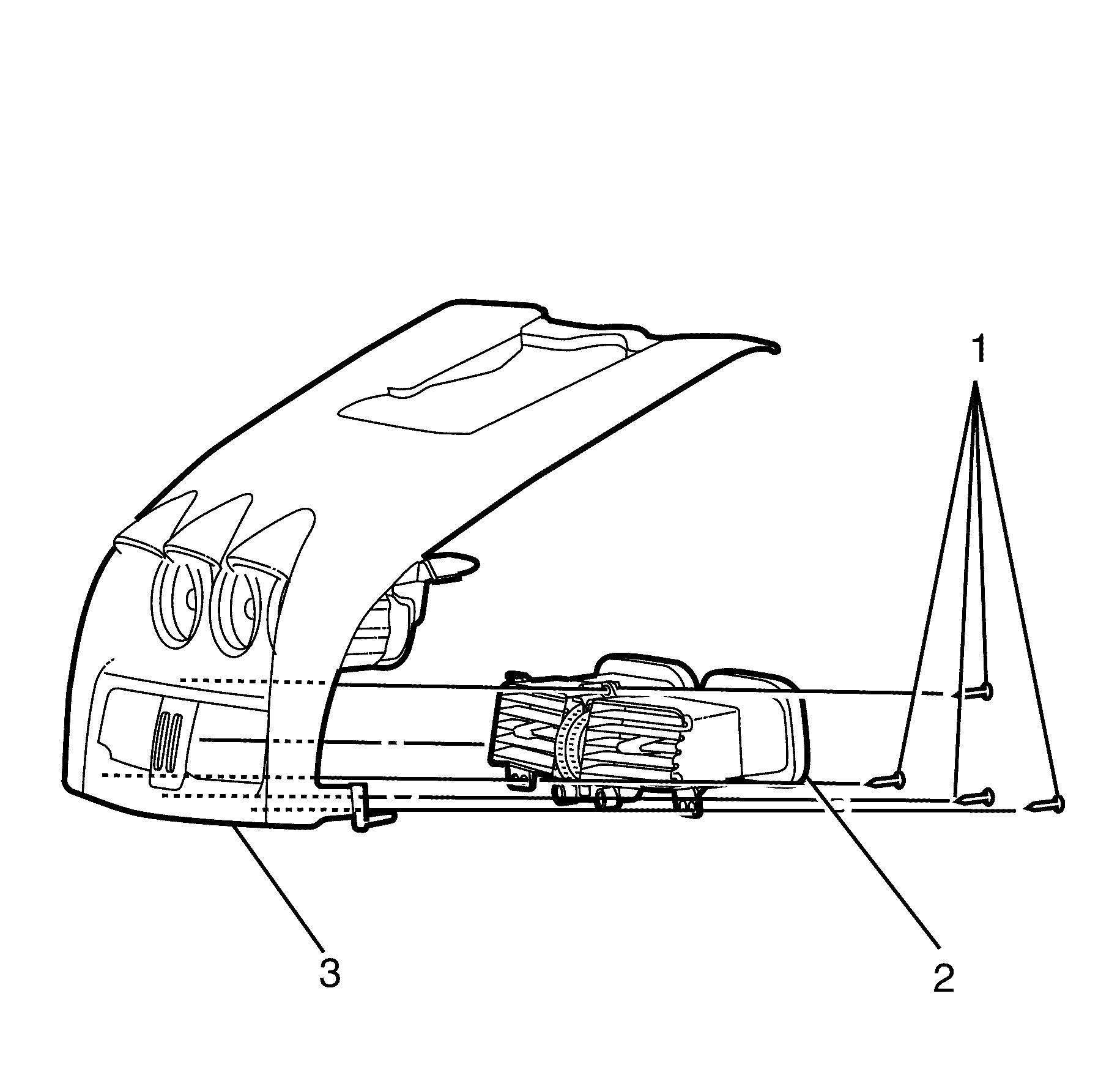
- Remove the vent retention screws (1) and disengage the vent assemblies (2) from the back of the SIC housing (3).
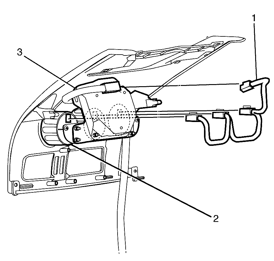
- Disconnect the electrical harness (1) from the SIC gauges (2) and the SIC module (3).
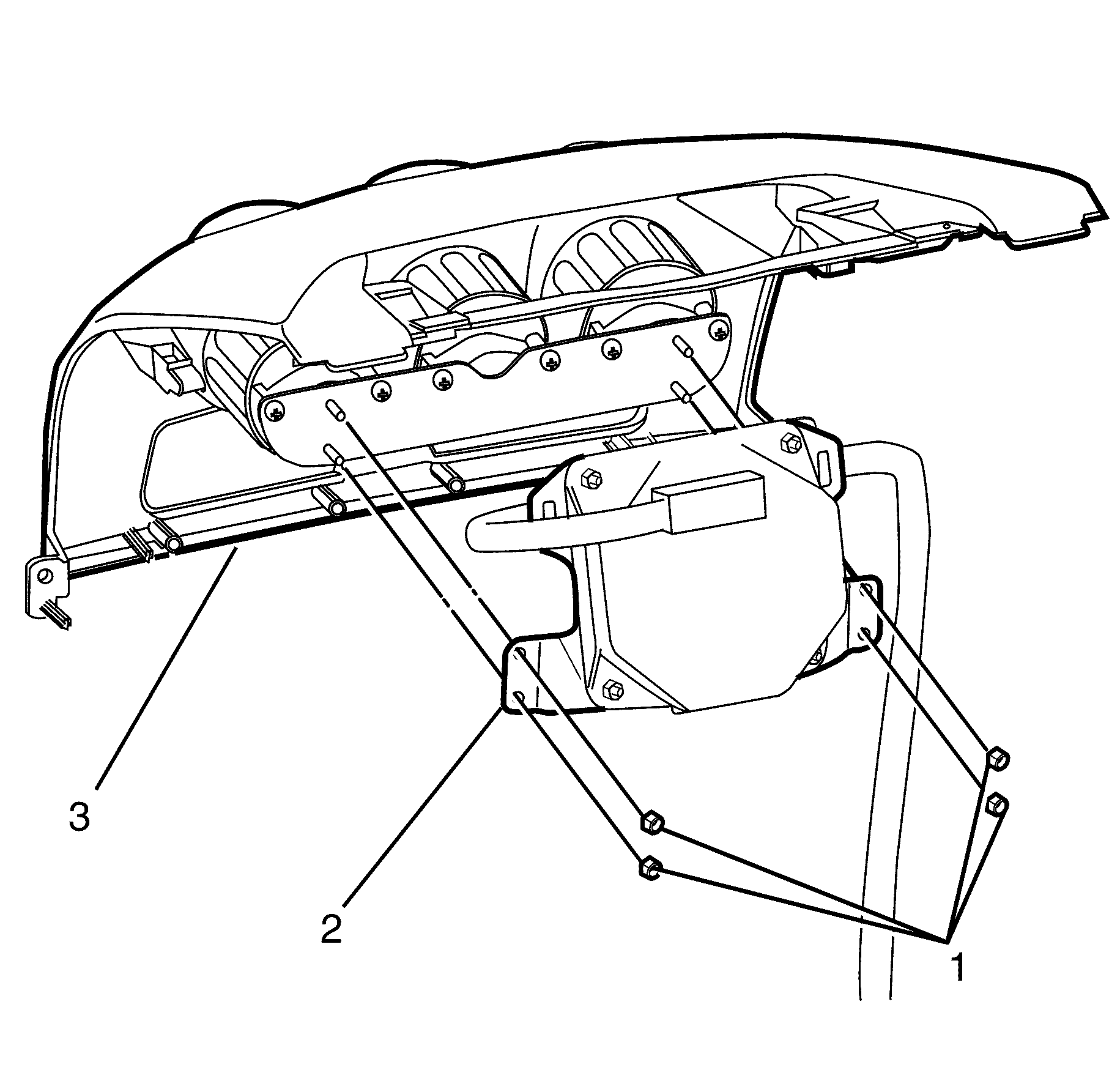
- Remove the SIC module to gauge alignment plate retaining nuts (1) from the back of the SIC module (2).
- Remove the SIC module from the SIC housing (3).
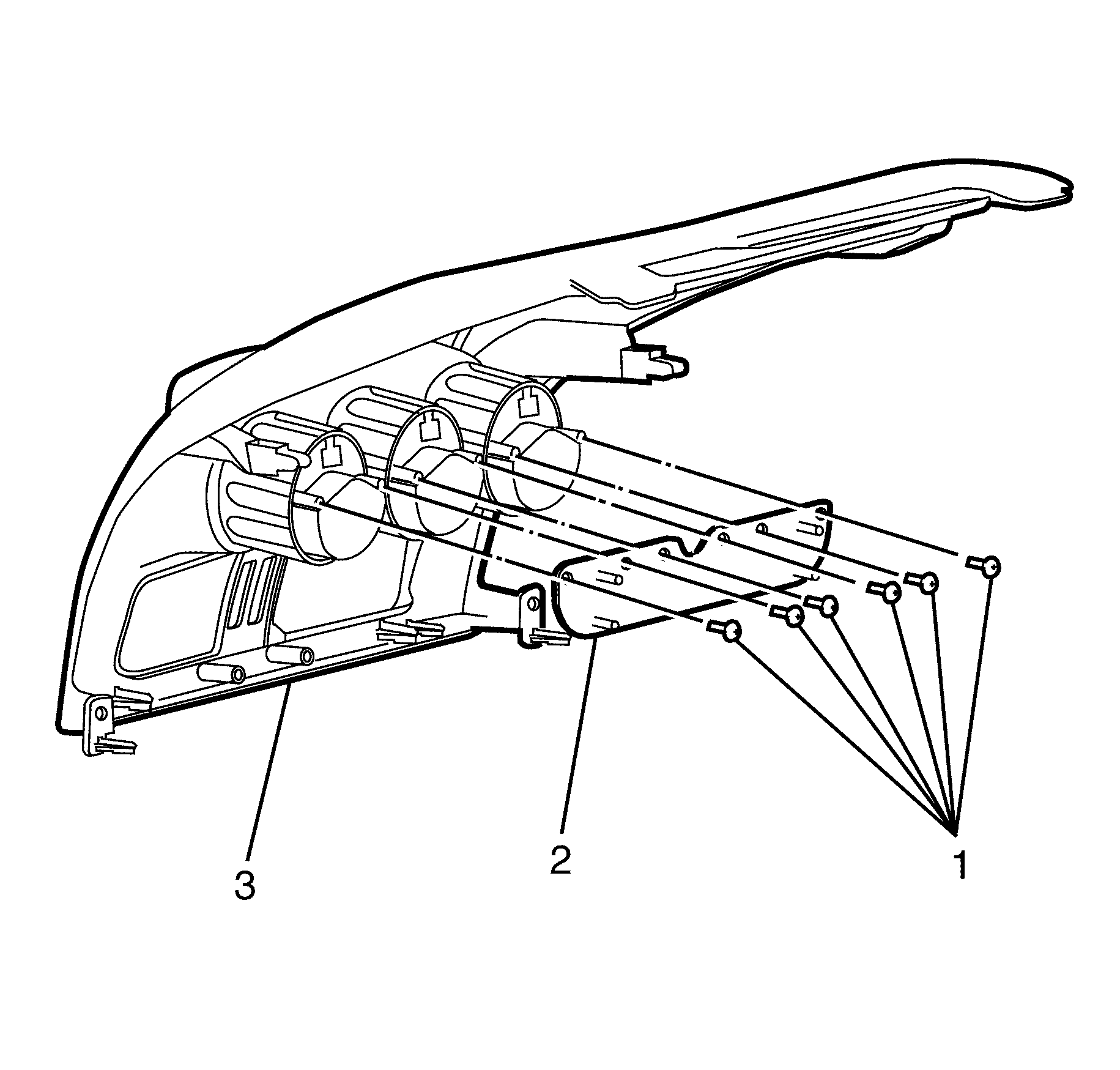
- Remove the gauge alignment plate retaining screws (1) from the gauge alignment plate (2).
- Remove the gauge alignment plate (2) from the SIC housing (3).
- Unscrew and remove the rear housing of the gauge assembly (1).
- Push the gauge body (3) out through the front of the SIC housing (2).
- Replace as necessary.
Important: This procedure is only applicable with vehicles equipped with secondary information centre (SIC).
Important: The faulty gauge can be removed independently from the SIC housing without removing the remaining functional gauges.
Important: Not all vehicles are equipped with Electronic Suspension Control (ESC). If vehicle is not fitted with ESC proceed to step 4.
Installation Procedure
- Install the gauge (3) into the SIC housing (2).
- Install the rear body of the gauge (1) in a clockwise direction until tight.
- Install the gauge alignment plate (2) to the SIC housing (3).
- Install the gauge alignment plate retaining screws (1).
- Install the SIC module (2) to the SIC housing (3).
- Connect the electrical harness (1) to the SIC module (3) and the SIC gauges (2).
- Install the ESC switch into the SIC housing. Refer to Electronic Suspension Switch Replacement.
- Install the SIC housing to the I/P. Refer to Secondary Driver Information Display Replacement.
- Connect the battery negative cable to the battery. Refer to Battery Negative Cable Disconnection and Connection.
- Turn on the Engine.
- Test the system.
- Perform the Diagnostic System Check - Vehicle.

Important: Make sure the gauge is installed correctly and aligned.

Notice: Refer to Fastener Notice in the Preface section.
Tighten
Tighten the screws (1) to 2 Nm (18 lb in).

Install the SIC Module (2) to SIC housing (3) retainer nuts (1).
Tighten
Tighten the nuts (1) to 2 Nm (18 lb in).

Important: Not all vehicles are equipped with ESC. If vehicle is not fitted with ESC, proceed to step 8.
