For 1990-2009 cars only
Removal Procedure
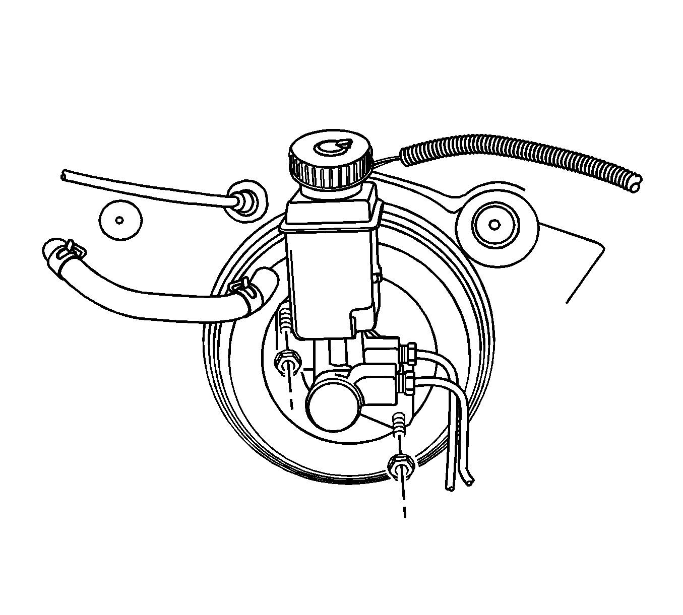
- Remove the master cylinder. Refer to Master Cylinder Replacement.
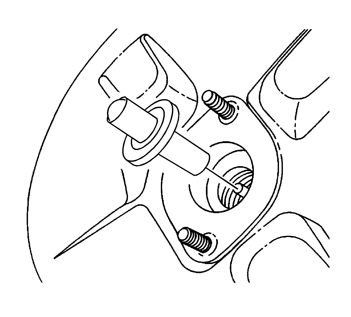
- Remove the shaft and the rubber O-ring.
- Spread the clip on the vacuum hose connection to the brake booster and move the clip away from the booster.
- Remove the vacuum hose from the booster.
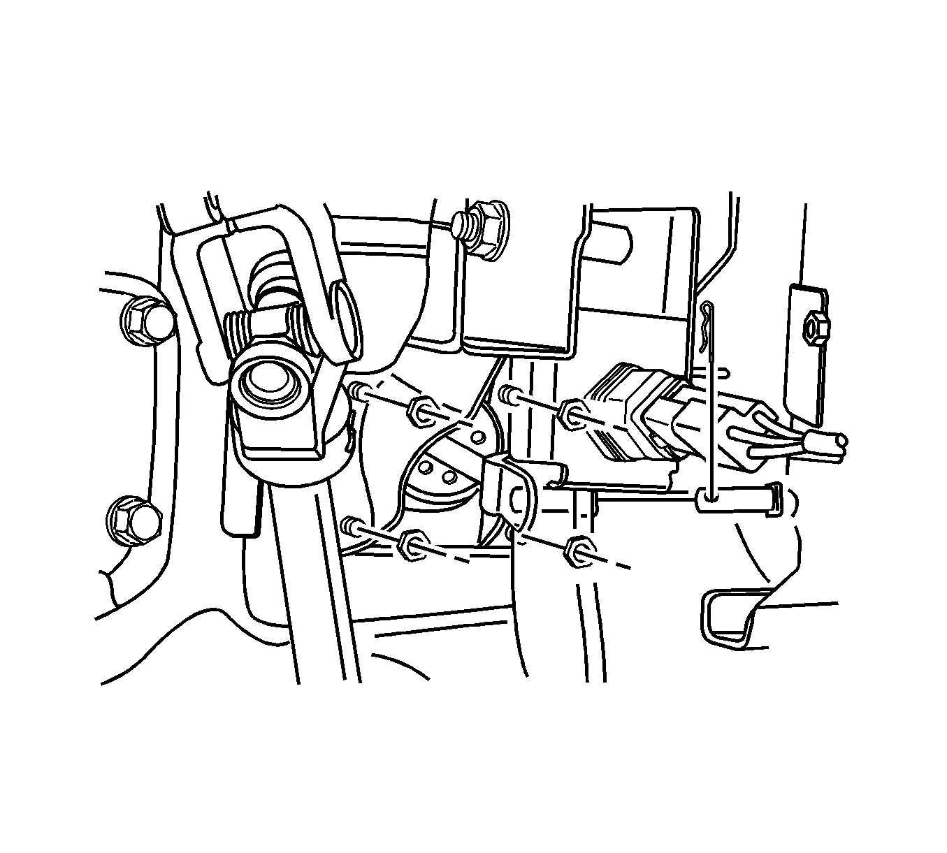
- Disconnect the stop lamp switch. Refer to Stop Lamp Switch Replacement.
- Remove the brake pedal spring.
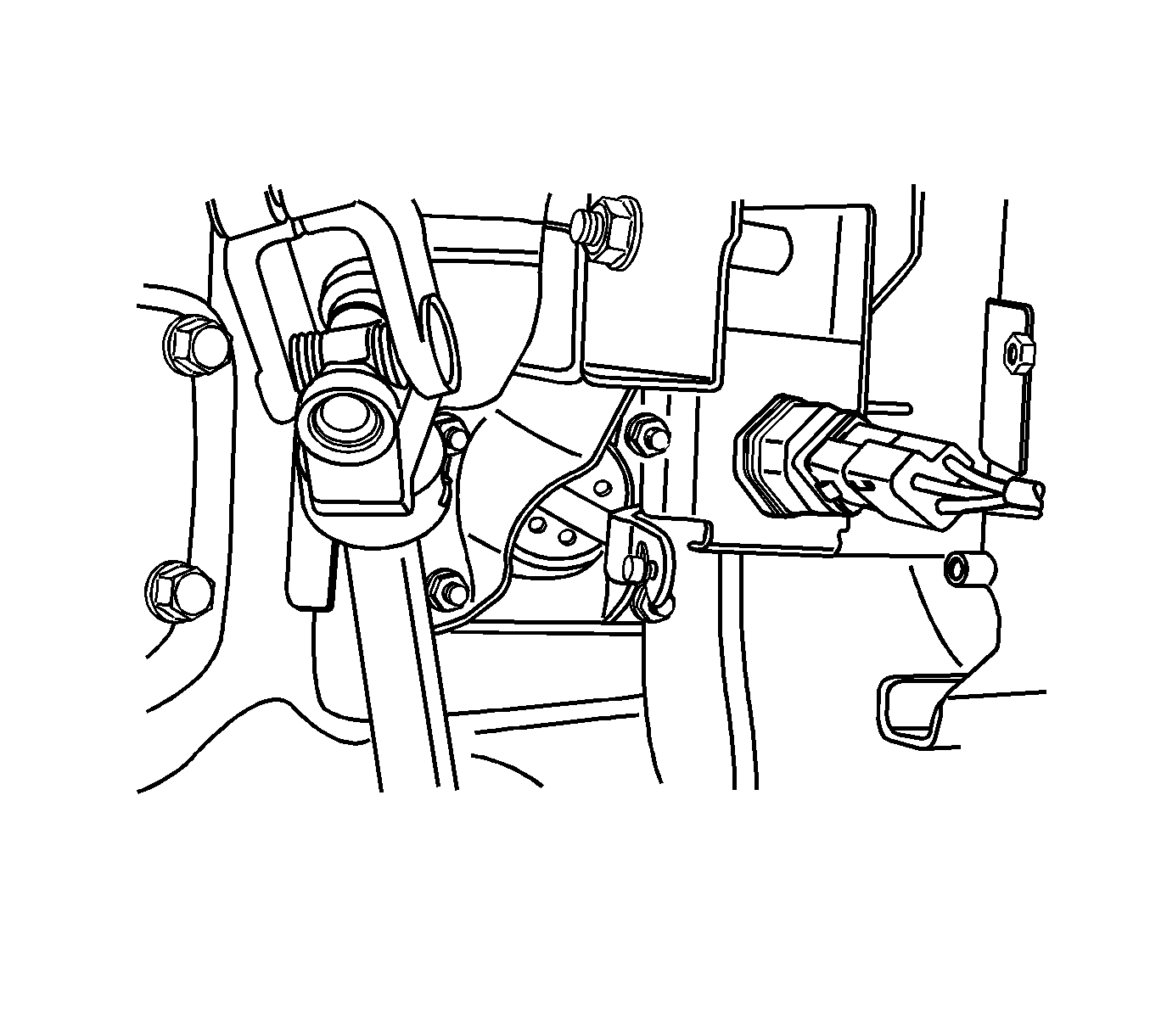
- Remove the clip and the pushrod pin from the pedal bracket assembly.
- Remove the booster mounting nuts from the studs protruding from the dash panel and remove the booster.
- Remove the rubber boot.
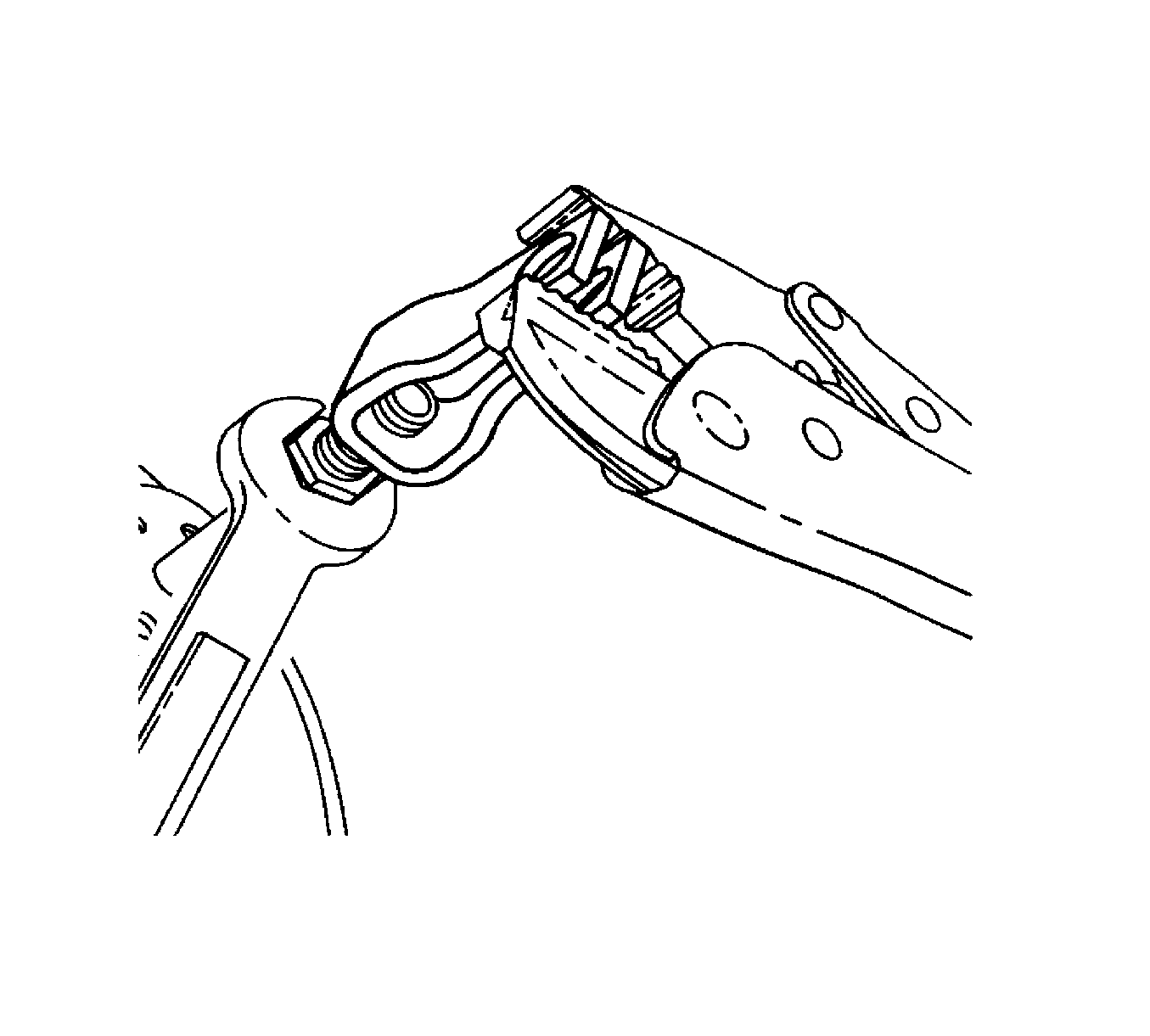
- Holding the hex nut, twist off the pushrod clevis.
- Remove the hex nut from the pushrod.
Installation Procedure
- Inspect the pushrod and the pushrod clevis for damage and proper fit.
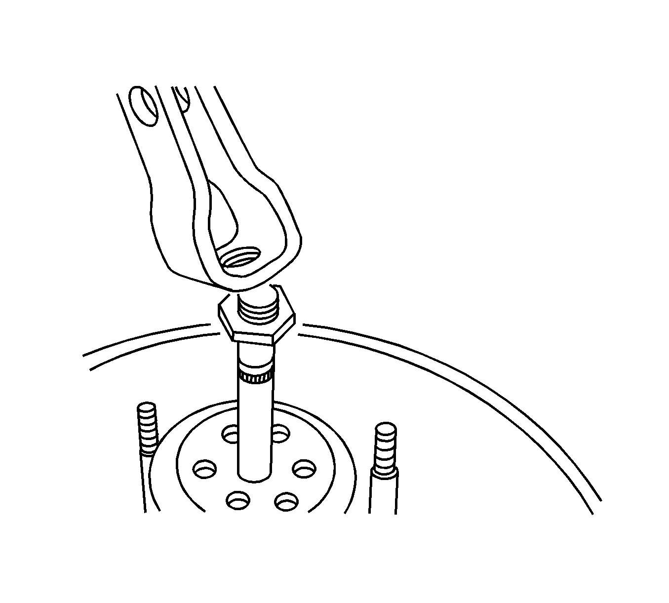
- Install the hex nut and the pushrod clevis on the booster shaft.
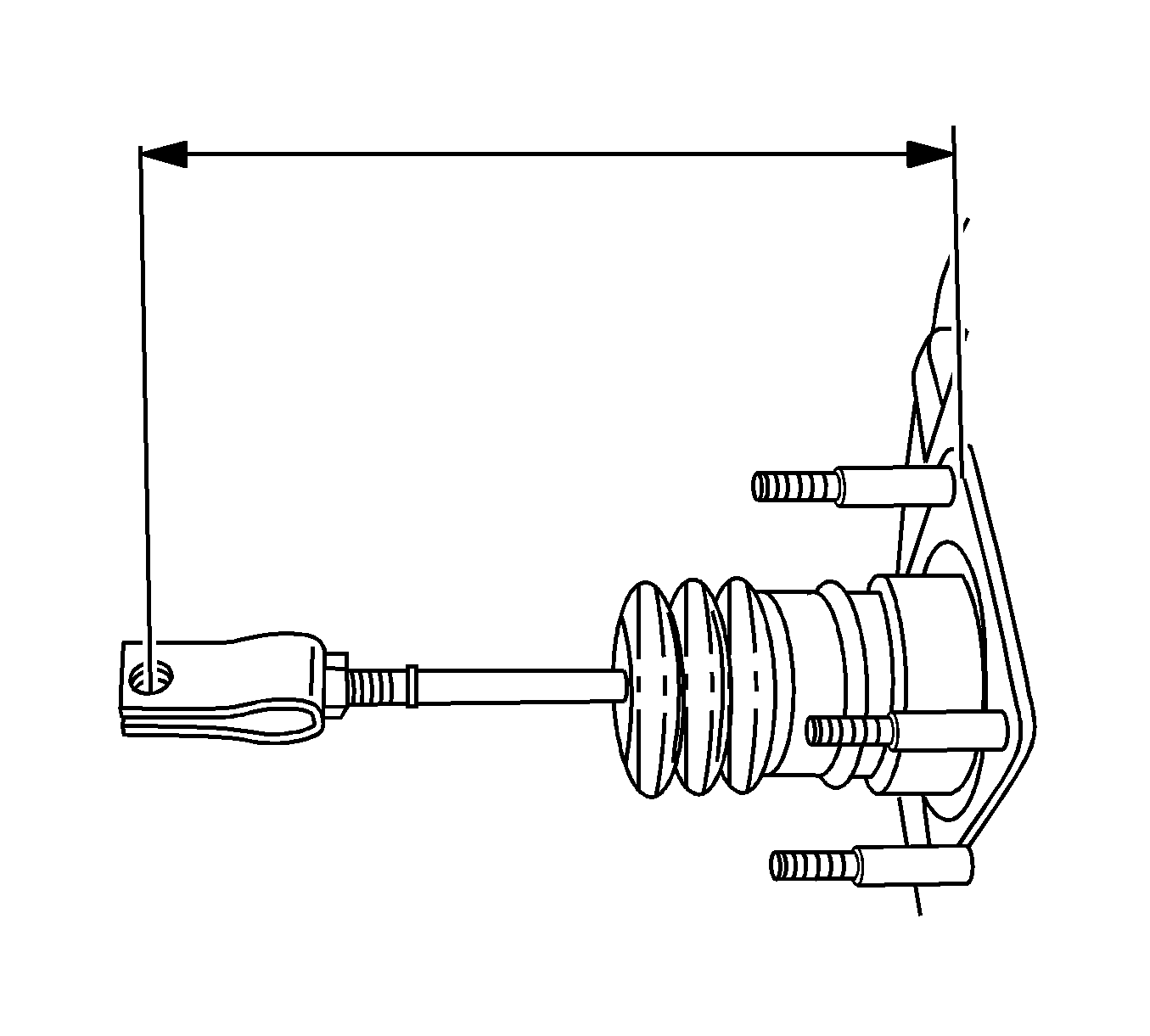
- Measure the distance from the booster to the center of the fork pin bore.
- Install the rubber boot to the booster.
- Install the booster hex nut and the pushrod clevis and tighten to 18 N·m (13 lb ft).
- Install the booster and the mounting nuts to the dash panel and tighten to 22 N·m (16 lb ft).
- Attach the shaft and the rubber O-ring.
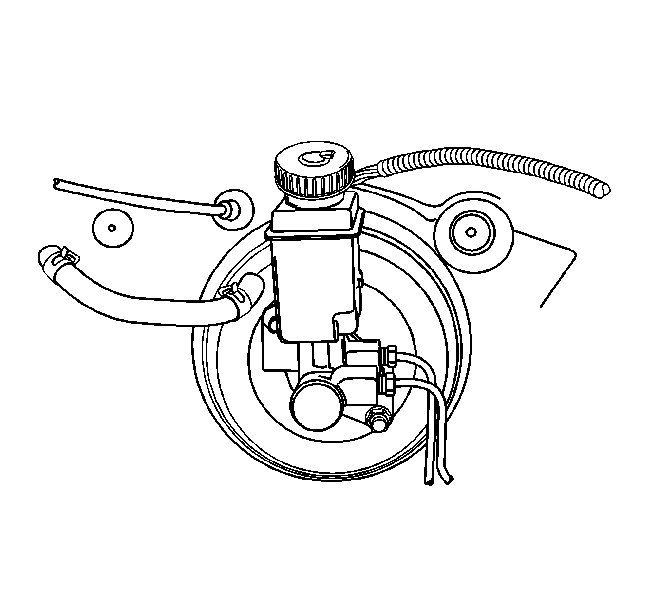
- Connect the master cylinder to the booster. Refer to Master Cylinder Replacement.
- Connect the brake line fittings to the hydraulic modulator, if applicable, and tighten.
- Install the vacuum hose and the clip to the booster.
- Install the hose clamps on the vacuum hose, and snap the vacuum hose in the revolving clip.
- Ensure the vacuum hose connections are tight at each end.
- Install the pushrod pin to the brake pedal bracket assembly and connect the clip and the spring.
- Install the stop lamp switch. Refer to Stop Lamp Switch Replacement.
Specification
The distance from the booster to the center of the fork pin bore should be 120 mm (4.7 in).
Caution: Refer to Fastener Caution in the Preface section.

| • | brake line fittings to 16 N·m (12 lb ft) |
| • | master cylinder attaching nuts to 24 N·m (18 lb ft). |

