Removal Procedure
- Relieve the fuel system pressure. Refer to Fuel Pressure Relief .
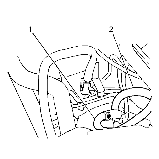
- Disconnect the EVAP purge hose (1) from the EVAP purge pipe in the engine compartment.
- Disconnect the EVAP air inlet hose (2) from the EVAP air inlet pipe in the engine compartment.
- Raise and suitably support the vehicle. Refer to Lifting and Jacking the Vehicle in General Information.
- Remove the fuel tank. Refer to Fuel Tank Replacement .
- Disconnect the left rear wheel hydraulic brake line. Refer to Brake Fluid and Brake Fluid Handling in Hydraulic Brakes.
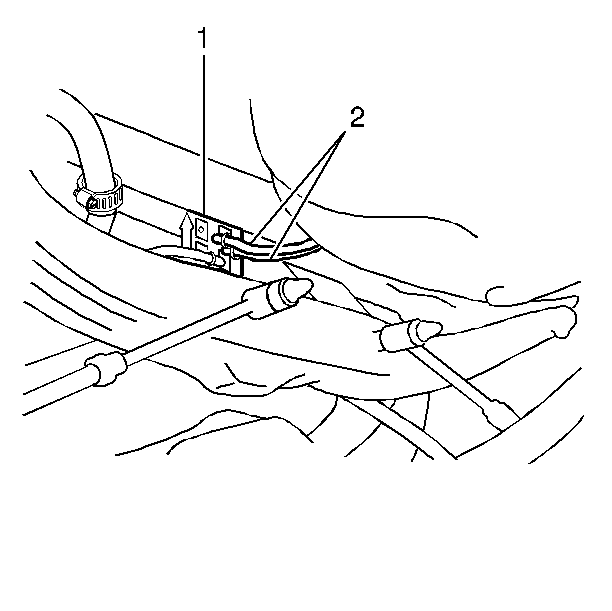
- Disconnect the EVAP canister purge hose (2) from the EVAP purge pipe.
- Disconnect the EVAP canister air inlet hose (2) from the EVAP air inlet pipe.
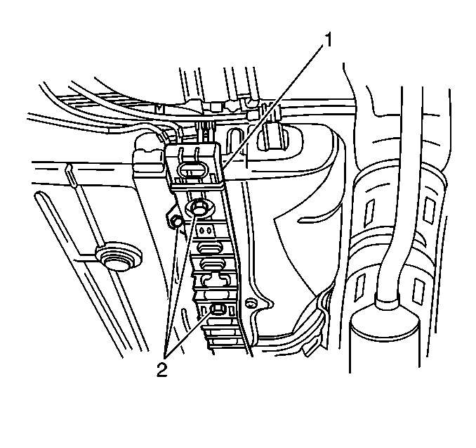
- Remove the four nuts (2) and the one bolt from the EVAP/fuel pipe protector (1).
- Remove the EVAP/fuel pipe protector (1) from the vehicle underbody.
- Remove the two bolts from the two EVAP pipe support brackets at the rear of the vehicle.
- Remove the one bolt from the EVAP pipe front bulkhead support.
- Slide the ends of the two EVAP pipes out of the EVAP bracket (1) located at the center of the underbody near the EVAP canister.
- Remove the two EVAP pipes from the vehicle underbody.


Installation Procedure
- Install the two EVAP pipes to the vehicle underbody.
- Insert the ends of the two EVAP pipes into the EVAP bracket (1) located at the center of the underbody near the EVAP canister.
- Install the EVAP/fuel pipe protector (1) to the vehicle underbody.
- Install the four nuts (2) and the one bolt to the EVAP/fuel pipe protector (1).
- Secure the EVAP pipe front bulkhead support with the one bolt.
- Secure the two EVAP pipe support brackets at the rear of the vehicle with two bolts.
- Connect the EVAP canister purge hose (2) to the EVAP purge pipe.
- Connect the EVAP canister air inlet hose (2) to the EVAP air inlet pipe.
- Connect the left rear wheel hydraulic brake line and bleed the brake system. Refer to Rear Brake Hose Replacement in Hydraulic Brakes.
- Install the fuel tank. Refer to Fuel Tank Replacement .
- Lower the vehicle.
- Connect the EVAP purge hose (1) to the EVAP purge pipe in the engine compartment.
- Connect the EVAP air inlet hose (2) to the EVAP air inlet pipe in the engine compartment.
- Connect the negative battery cable.
- Turn ON the ignition in order to pressurize the fuel system.
- Turn OFF the ignition.
- Check for any fuel leaks.


Notice: Use the correct fastener in the correct location. Replacement fasteners must be the correct part number for that application. Fasteners requiring replacement or fasteners requiring the use of thread locking compound or sealant are identified in the service procedure. Do not use paints, lubricants, or corrosion inhibitors on fasteners or fastener joint surfaces unless specified. These coatings affect fastener torque and joint clamping force and may damage the fastener. Use the correct tightening sequence and specifications when installing fasteners in order to avoid damage to parts and systems.
Tighten
Tighten the four nuts and the bolt to 1.2-2.0 N·m
(11-18 lb in).
Tighten
Tighten the front bulkhead support bolt to 6 N·m (53 lb in).
Tighten
Tighten the two rear support bracket bolts to 6 N·m (53 lb in).


Tighten
Tighten the negative battery cable terminal retainer to 15 N·m
(11 lb ft).
