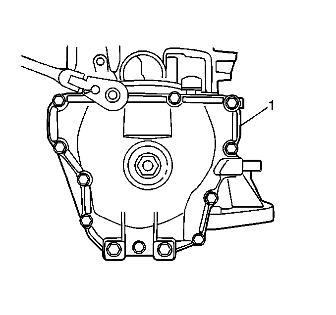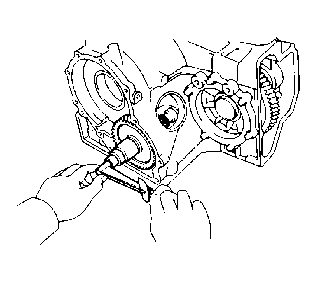
- Use a torque wrench in
order to measure the total preload.
The total preload should be within the following range:
| • | The total preload with a new bearing should be 0.3-0.4 N·m
(2.5-3.9 lb in). |
| • | The total preload with a reused bearing should be 0.1-0.2 N·m
(1.2-1.9 lb in). |
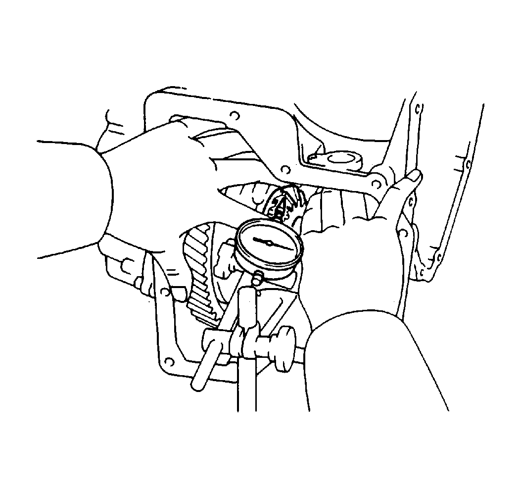
- Use J 8001
and J 25025-1
in order to measure the backlash of the side gear.
The standard backlash is 0.05-0.20 mm (0.0020-0.0079 in).
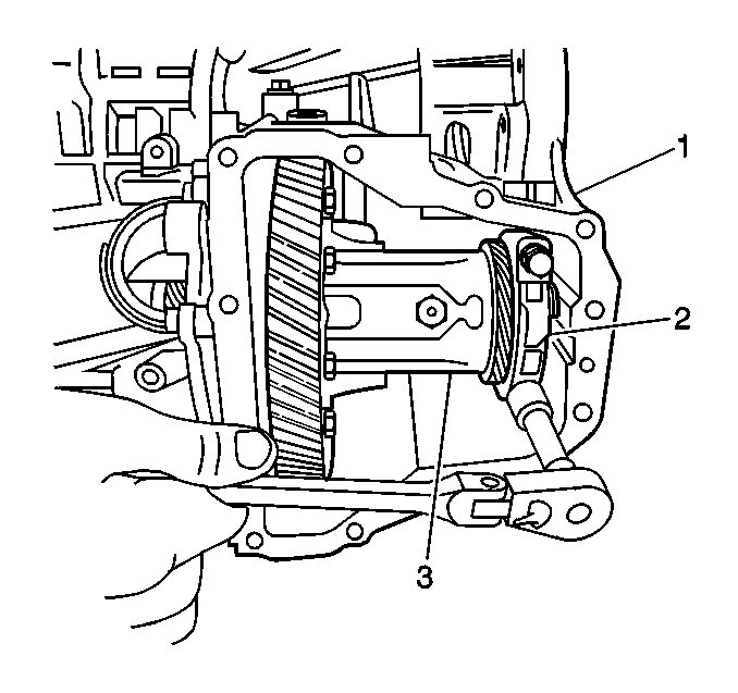
- Remove the right side
bearing cap (1) .
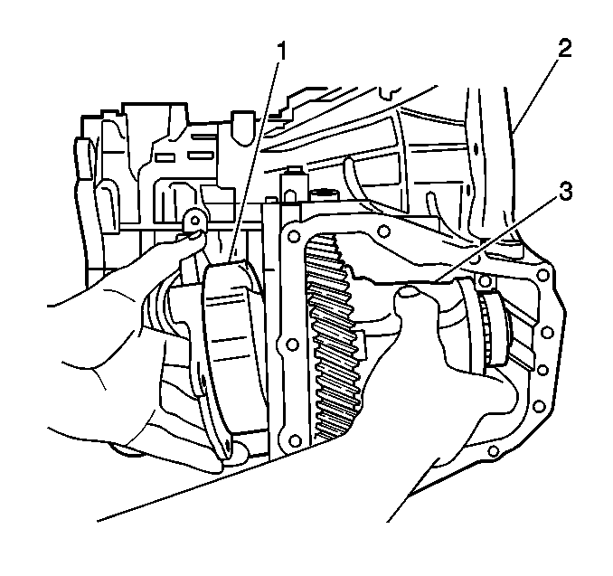
- Remove the 6 bolts
- Tap the left bearing retainer loose with a plastic hammer.
- Remove the retainer (1) .
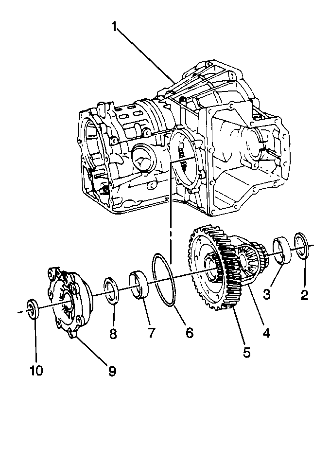
- Remove the O-ring (6)
from the retainer (9).
- Replace the oil seal (10), the shim (8), or the
outer race (7) if necessary.
- Set the retainer (9) to one side.
- Remove the following components from the differential case (1):
| • | The differential carrier (4) and ring gear (5) assembly |
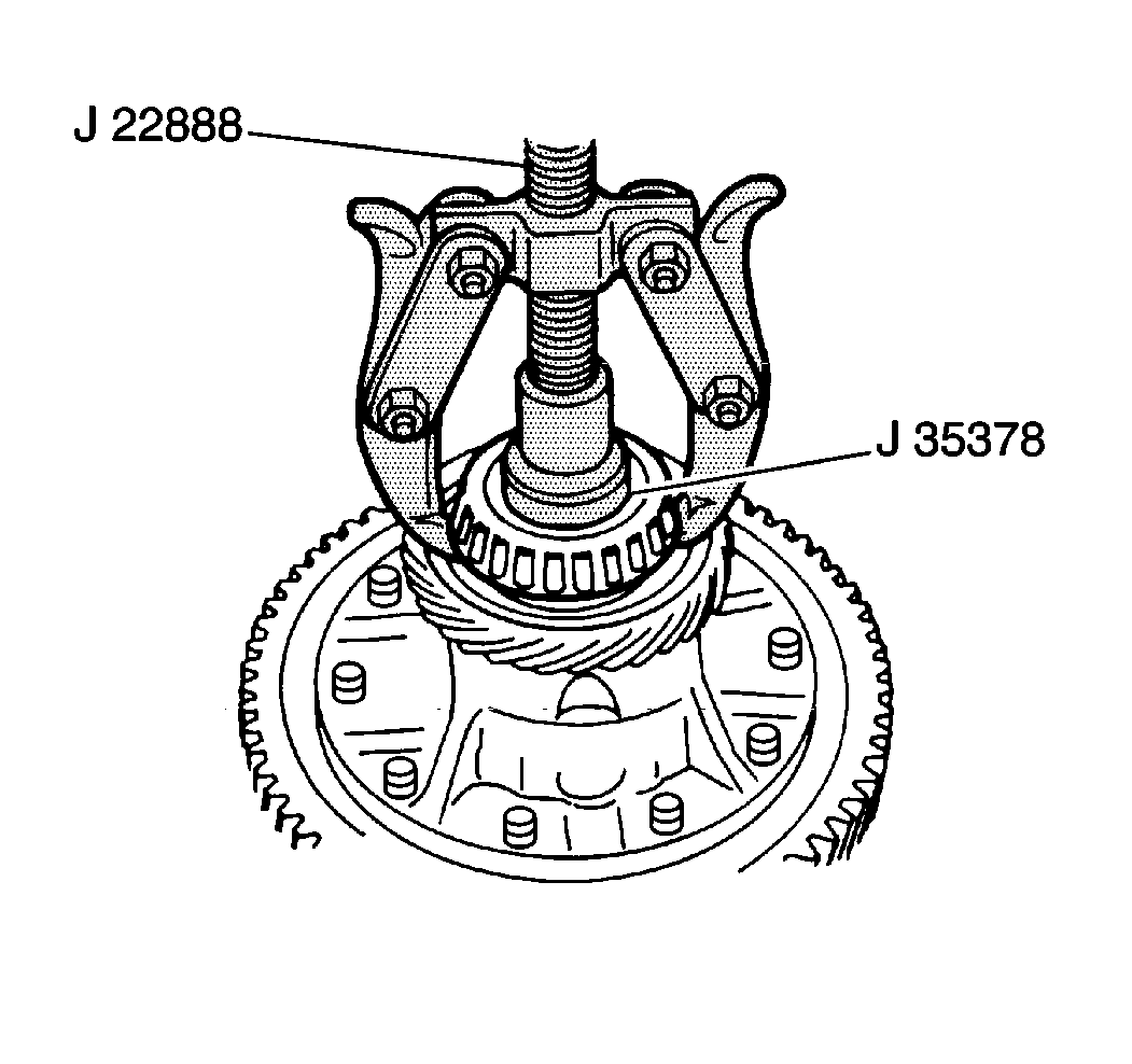
- Use J 22888-D
and J 35378
in order to remove the side bearing from the differential carrier.
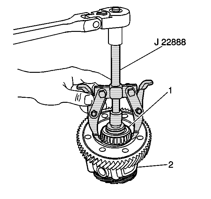
- Use J 22888-D
and J 35378
in order to remove the front bearing (1) from the differential
carrier (2).
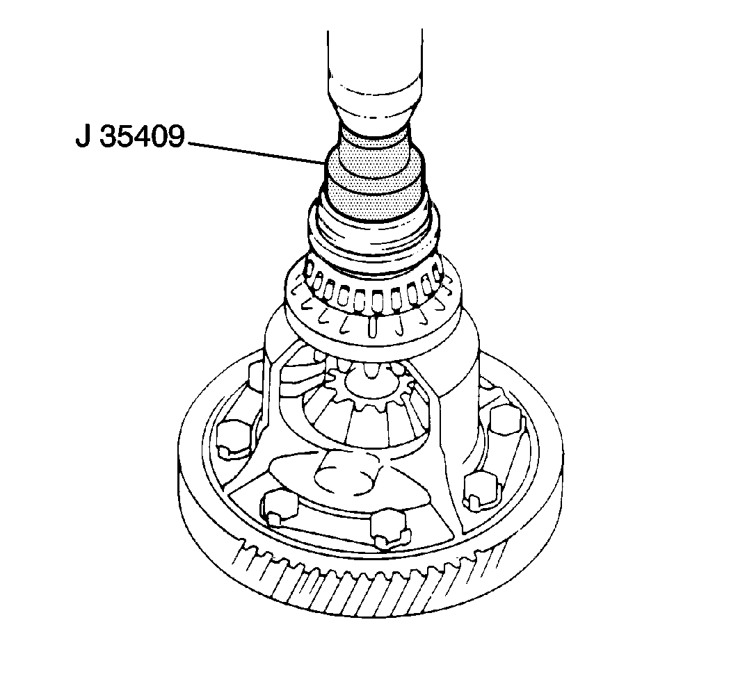
- Use the J 35409
in order to install the front bearing
and the side bearing to the differential carrier.
- Align the marks on the ring gear and the differential carrier.
- Remove the following components:
- Tap on the ring gear in order to remove it from the case.
- Loosely install the new set bolts and the plates.
Notice: Use the correct fastener in the correct location. Replacement fasteners
must be the correct part number for that application. Fasteners requiring
replacement or fasteners requiring the use of thread locking compound or sealant
are identified in the service procedure. Do not use paints, lubricants, or
corrosion inhibitors on fasteners or fastener joint surfaces unless specified.
These coatings affect fastener torque and joint clamping force and may damage
the fastener. Use the correct tightening sequence and specifications when
installing fasteners in order to avoid damage to parts and systems.
- Tighten the sets
bolts uniformly, a little at a time.
Tighten
Tighten the set bolts to 97 N·m (71 lb ft).
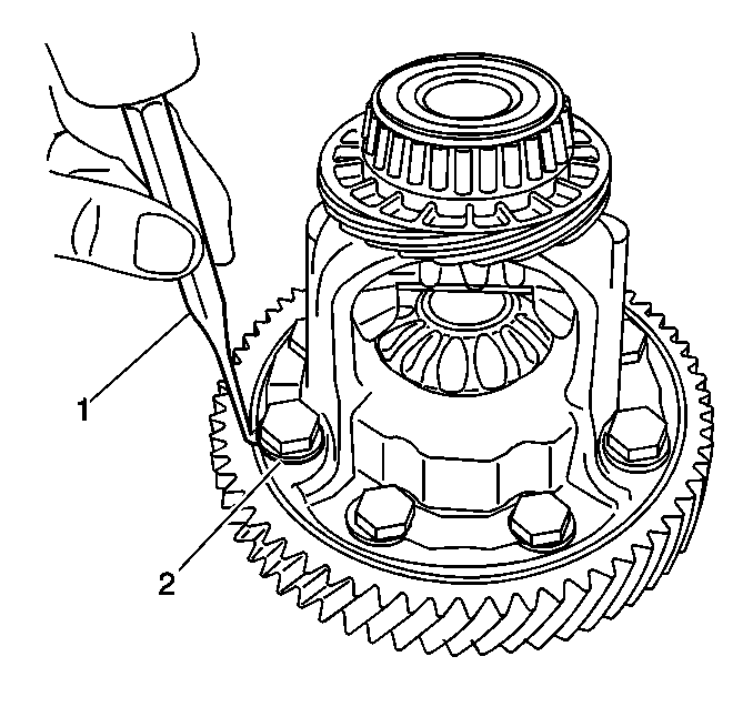
Important: Stake one claw (2) flush with the flat surface of the nut.
For the claw that contacts the protruding part of the nut, stake only
the half that is on the tightening side.
- Use a hammer and a drift punch in order to stake the locking plates.
- Hold one pinion and the one side gear toward the case
Measure the backlash of the other side gear.
| • | The standard backlash is 0.05-0.20 mm (0.0020-0.0079 in). |
| • | If the backlash is not within the specifications, install the
correct thrust washer to the side gears. |
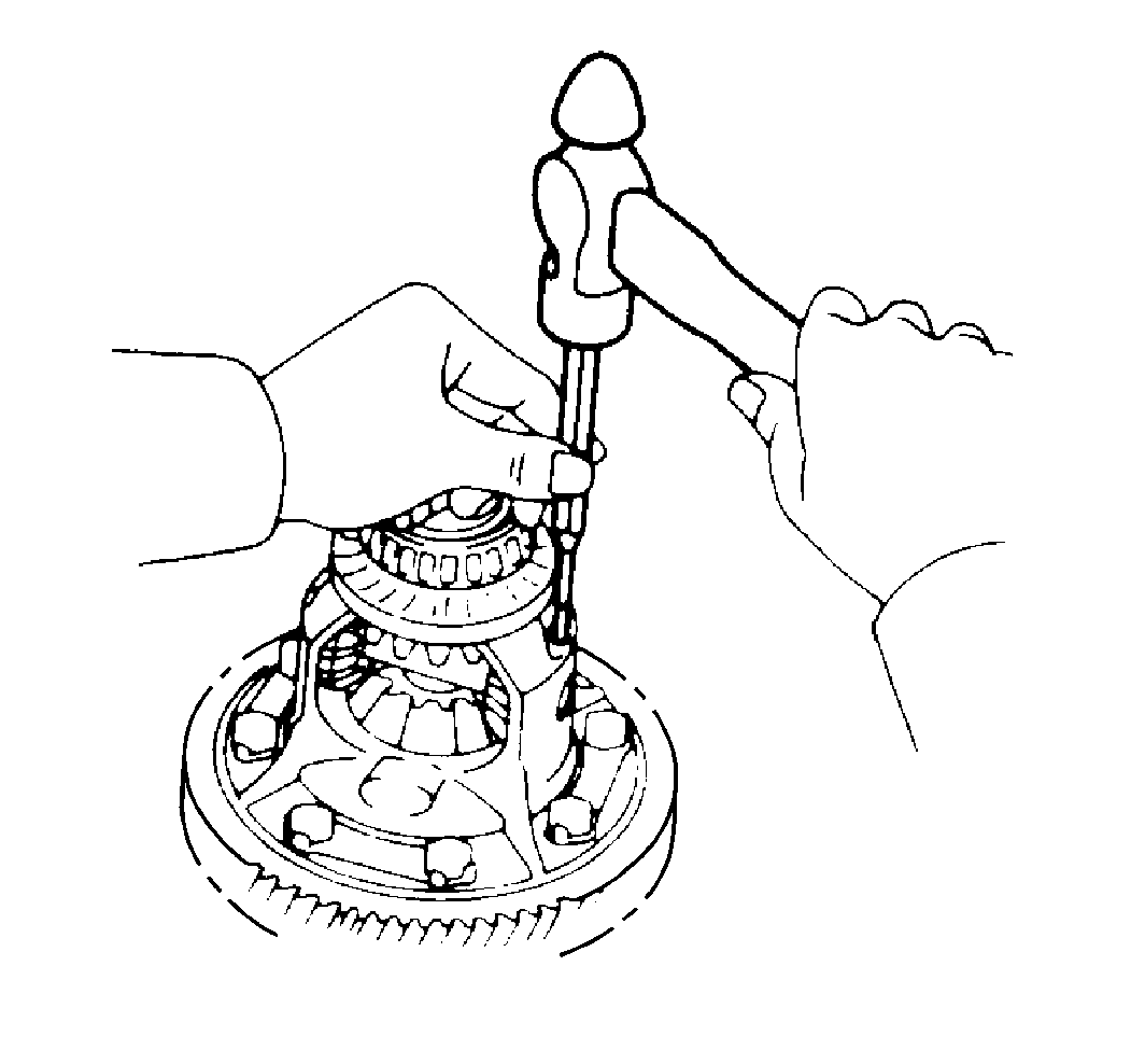
- Drive out the pinion shaft
lock pin from the side on which the ring gear is installed.
- Remove the pinion shaft from the case.
- Remove the following components:
