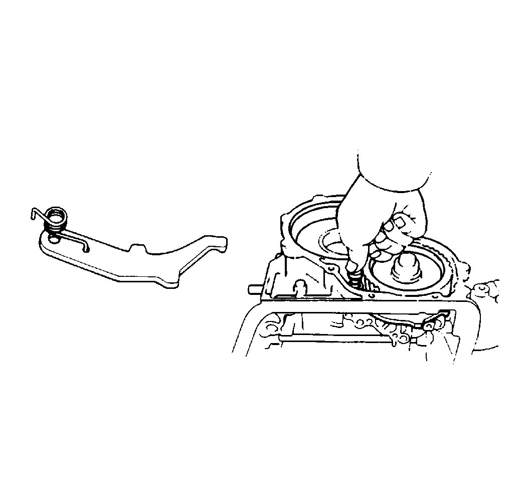
- Install the parking pawl
onto the case.
Hook the spring ends to the case and to the pawl.
- Install the pin into the hole of the case through the spring and
the pawl.
- Install the parking lock rod.
Notice: Use the correct fastener in the correct location. Replacement fasteners
must be the correct part number for that application. Fasteners requiring
replacement or fasteners requiring the use of thread locking compound or sealant
are identified in the service procedure. Do not use paints, lubricants, or
corrosion inhibitors on fasteners or fastener joint surfaces unless specified.
These coatings affect fastener torque and joint clamping force and may damage
the fastener. Use the correct tightening sequence and specifications when
installing fasteners in order to avoid damage to parts and systems.
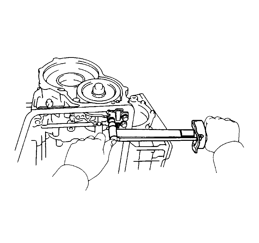
- Install the parking
lock pawl bracket.
Tighten
Tighten the bracket to 10 N·m (88 lb in).
- Inspect the operation of the parking lock pawl.
Verify that the counter driven gear locks when the manual valve lever
is in the P range.
- Install the governor sleeve and the keeper.
- Install the manual shaft and the seal. Install the spring clip
over the seal.
- Stake the new sleeve.
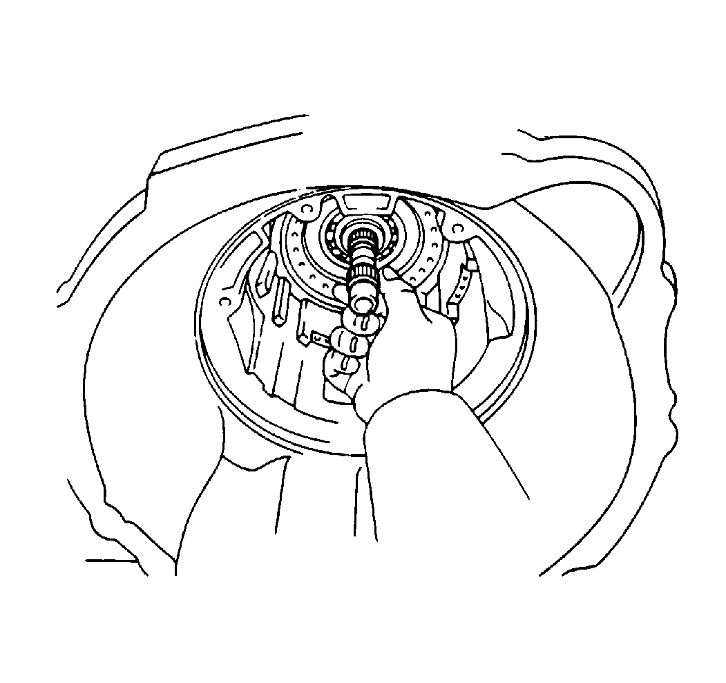
- Inspect the intermediate
shaft end play.
Specification
Thrust play should be 0.49-1.51 mm (0.0193-0.0594 in).
- If the thrust play is not within the specifications, inspect
the installation of the intermediate shaft. Verify that the intermediate shaft
turns smoothly.
- Install the first and reverse brake piston in the case. Install
the seals and the springs.
- Install the intermediate shaft.
- Apply J 36850
or equivalent.
- Install the transaxle rear cover and secure with bolts.
Tighten
Tighten the transaxle rear cover bolts to 25 N·m (18 lb ft).
- Install 6 discs and 6 plates alternately, beginning
with a disc.
- Install the outer flange.
Place the flat end of the outer flange toward the piston side.
- Align all of the plates and install the snap ring into the groove.
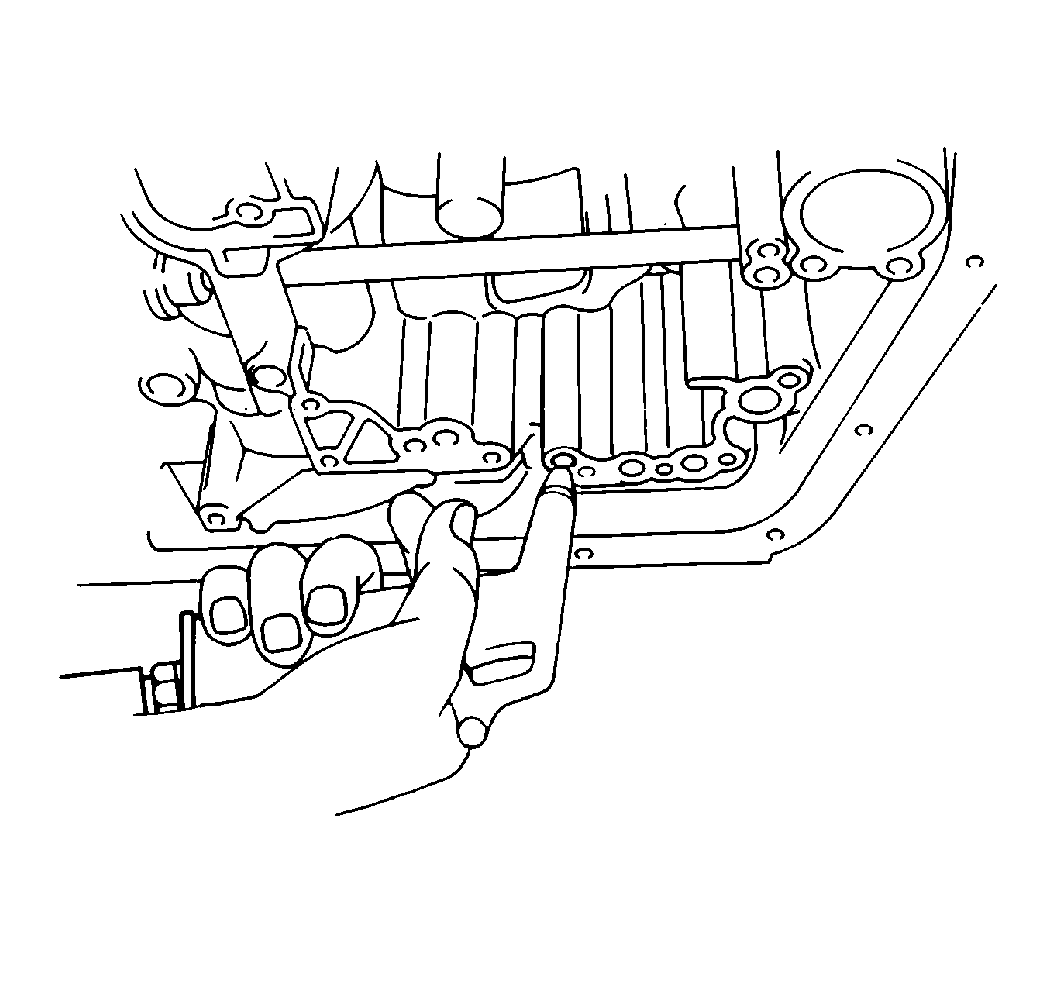
- Inspect the operation
of the first and reverse brake piston by applying compressed air into the
oil passage of the case. Verify that the piston moves.
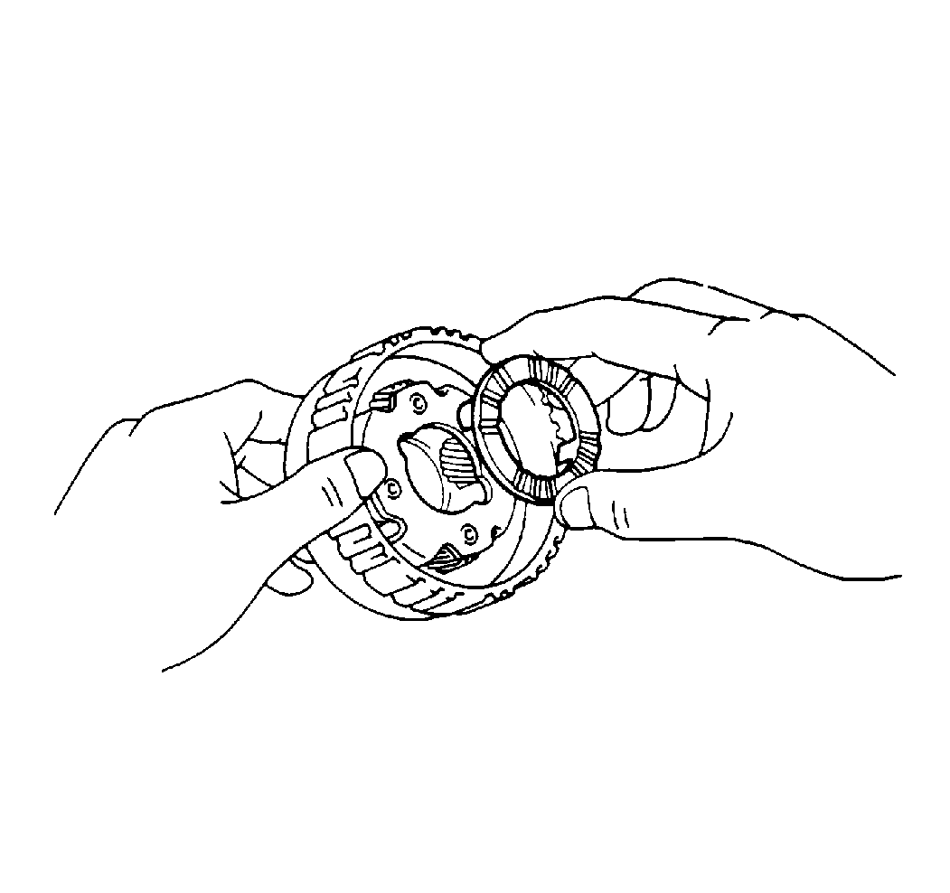
Important: Match the different lug shapes to the openings on the carrier.
- Coat the No. 2 planetary carrier thrust washer with the petroleum
jelly. Install the washer onto the planetary carrier.
- Install the ring gear into the case.
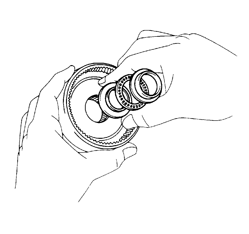
- Coat the races and the
bearings with petroleum jelly. Install the races and the bearings onto the
ring gear.
- Align the flukes of the discs in the first and reverse brake piston.
- Align the spline of the planetary carrier with the flukes of the
discs. Install the planetary gear into the first and reverse brake discs.
- With the shiny side facing upward, install the No. 2 one-way
clutch into the case.
- Install the one-way clutch onto the inner race while turning the
planetary gear clockwise.
- Coat the thrust washer with petroleum jelly.
- Install the thrust washer onto the planetary gear.
- Turn the planetary carrier:
| • | The carrier should turn freely when turned clockwise. |
| • | The carrier should lock when turned counterclockwise. |
- Install the snap ring with the end gap installed in the groove.
- Install the second coast brake band guide with the tip touching
the case.
- Install the second brake piston into the case. Install the flange
with the flat end facing outward.
- Install the clutch assembly.
Install the discs and the plates alternately, beginning with a disc.
- Install the piston return spring assembly. Position each of the
springs over the protrusions in the case.
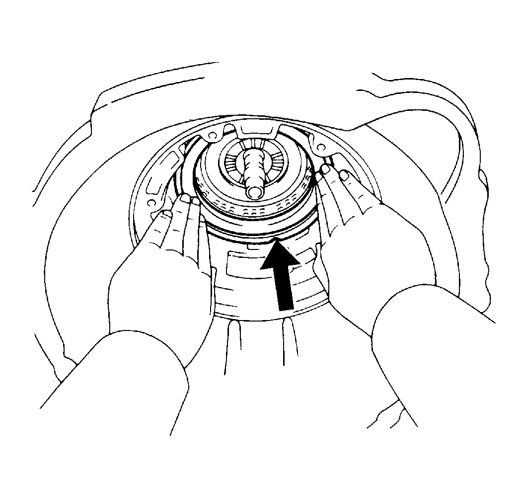
- Install the second brake
drum into the case, aligning the groove of the drum with the bolt.
- Place the snap ring into the case so that the end gap fits into
the groove.
- While compressing the piston return springs over the drum with
a hammer handle, install the snap ring into the groove.
- Inspect the operation of the second brake by applying compressed
air into the oil passage of the case. Verify that the piston moves.
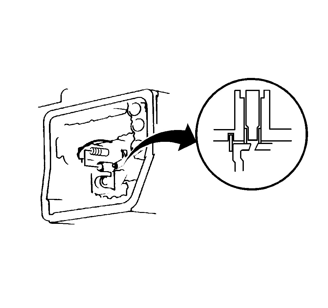
- Install the second brake
drum gasket until the gasket makes contact with the second brake drum.
- Install the No. 1 one-way clutch and second brake hub.
- Align the flukes of the discs in the second brake piston.
- Align the spline of the second brake hub with the flukes of the
discs, and install the hub to the second brake discs.
- Install the sun gear and the sun gear input drum. While turning
the sun gear clockwise, install the sun gear into the one-way clutch.
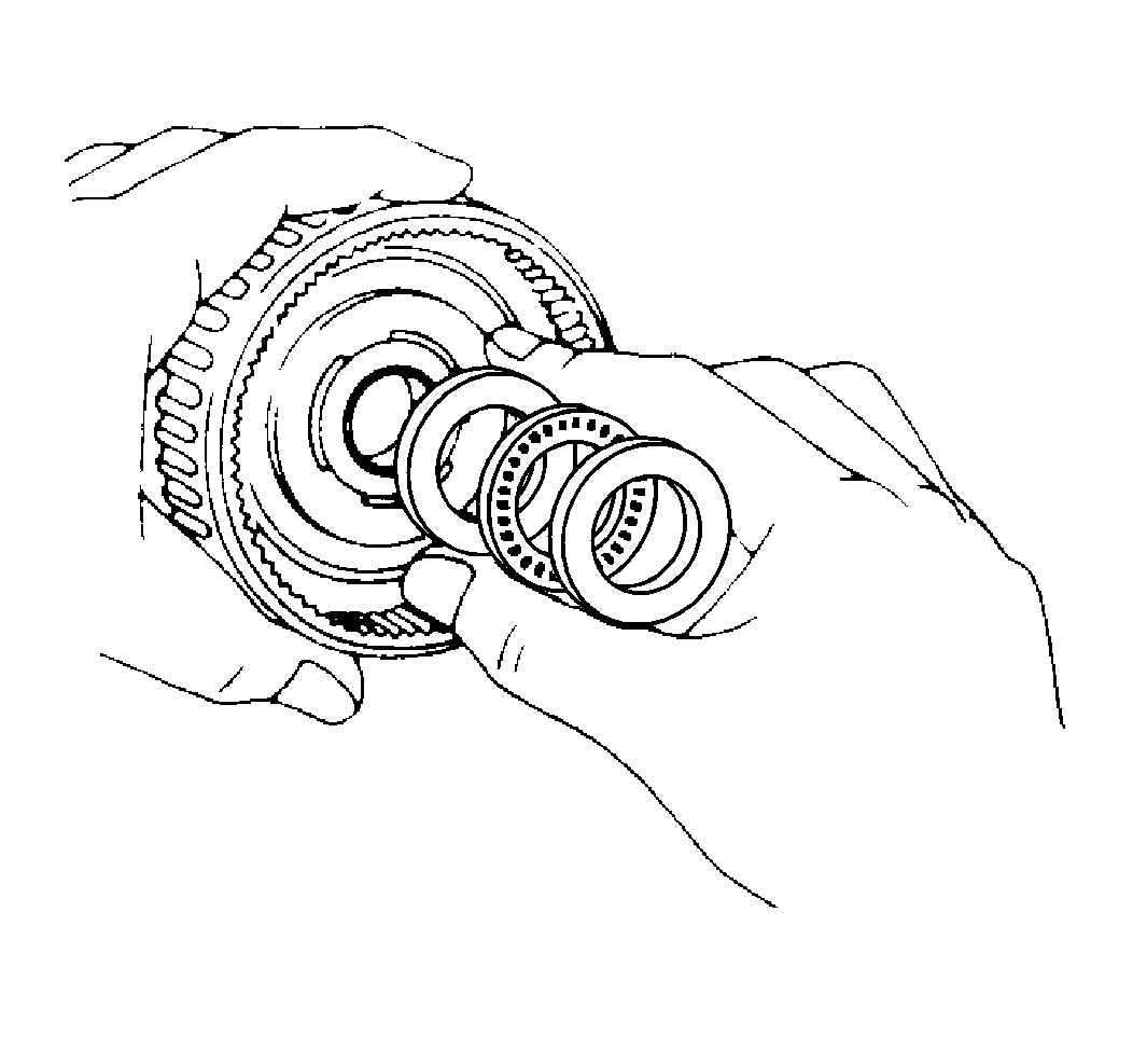
- Install the front planetary
gear and the ring.
- Coat the race and the bearing with petroleum jelly.
Install the race and the bearing onto the front planetary gear.
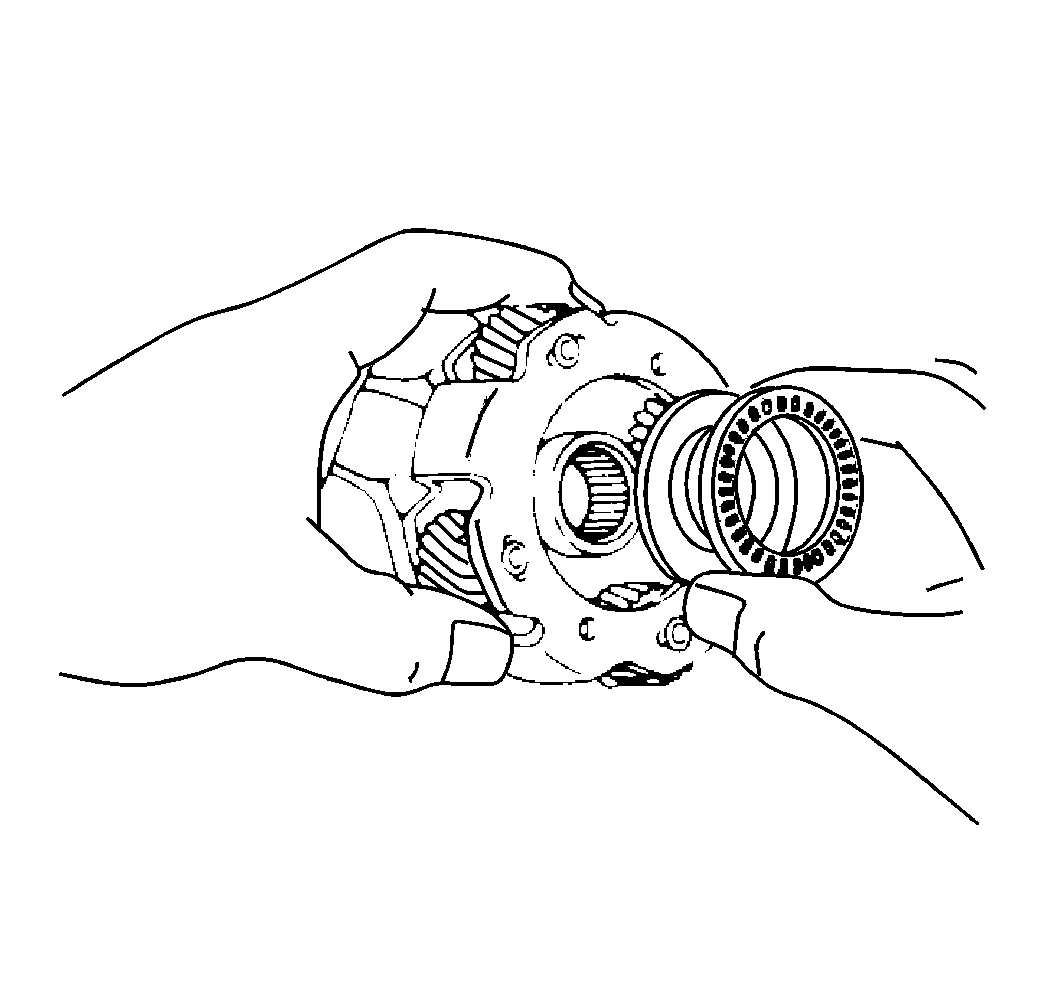
- Install the front planetary
gear into the case.
- Install the race and the bearing.
- Install the intermediate shaft oil seal ring.
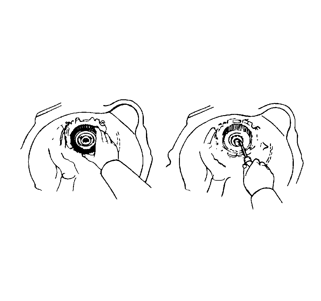
- Install the ring gear.
- Verify that the planetary gear and the other parts are installed
correctly into the case. The end of the bushing with the ring gear flange
should be flush with a shoulder of the intermediate shaft.
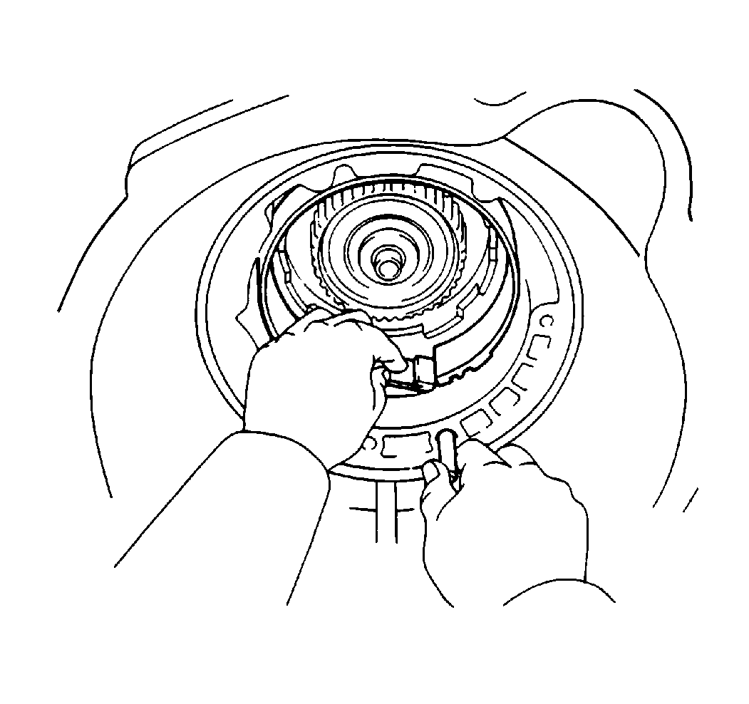
- Install the second coast
brake band by installing the pin through the hole on the oil pump mounting
bolt.
- Install the forward clutch into the case.
- Coat the races and the bearings with petroleum jelly. Install
the races and the bearings onto both sides of the clutch drum.
- Align the flukes of the disc in the forward clutch. Hold the sun
gear input drum and rotate the input shaft. This action will mesh the hub
with the discs of the forward clutch.
- Align the centers of the input shaft and the intermediate shaft.
Push and rotate the input shaft in order to mesh the hub and the disc.
- Verify that the flukes of the discs are meshed with the hub correctly.
If correct, the protrusion of the input shaft drum will enter deeper than
the tip of the sun gear input drum.
- Install the direct clutch into the case.
- Coat the clutch drum thrust washer with petroleum jelly.
- Install the clutch drum thrust washer onto the drum.
Place the oil groove upward.
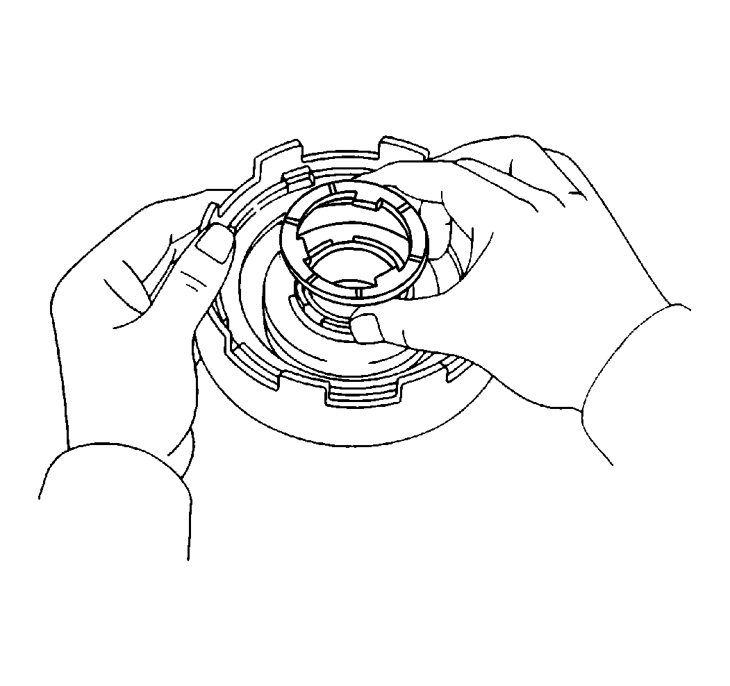
- Align the flukes of the
discs in the direct clutch.
- Hold the input shaft and put the direct clutch drum through in
the second coast brake band.
- While you are turning the clutch drum, mesh the flukes of the
direct clutch with the hub.
Verify that the flukes are meshed incorrectly. If correct, the end of
the bushing with the direct clutch drum will be flush with the thrust bearing
on the forward clutch.
- Install the oil pump into the case.
- Measure the input shaft thrust play.
- If the input shaft thrust play is in excess of the standard, insert
one of the two different size shims.
- Coat the race with petroleum jelly.
- Install the race onto the stator shaft.
- Lightly coat the O-ring with GM P/N 1050169 lube.
- Install an O-ring around the oil pump body.
- Install the oil pump with the O-ring gasket through the input
shaft. Align the bolt holes of the oil pump body with the transaxle case.
Notice: Do not push excessively hard on the oil pump or the oil seal ring will
stick to the direct clutch drum.
- Holding the input shaft, lightly press the oil seal rings on the stator
shaft through the direct clutch drum.
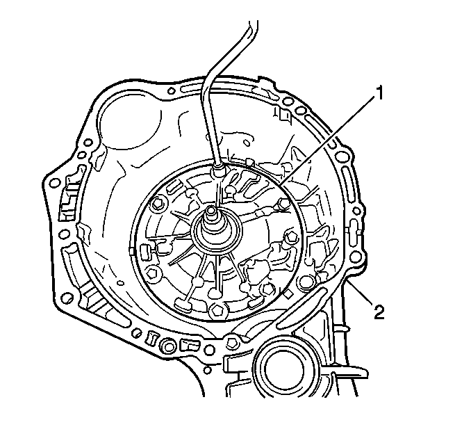
- Install the oil pump (1) retaining
bolts.
Tighten
Tighten the oil pump retaining bolts to 22 N·m (16 lb ft).
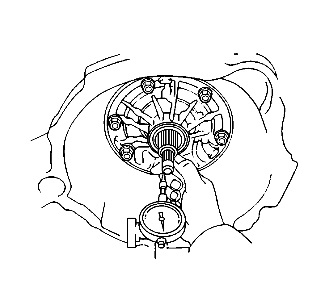
- Measure the thrust play
of the input shaft.
Measurement
The thrust play should be 0.3-0.9 mm (0.012-0.035 in).
- If necessary, install one of the following thicknesses of race
at the end of the stator shaft:
- Verify that the input shaft rotates freely.
- Inspect the second coast brake piston stroke.
- Install the brake piston (without the outer spring) into the bore.
Install the snap ring.
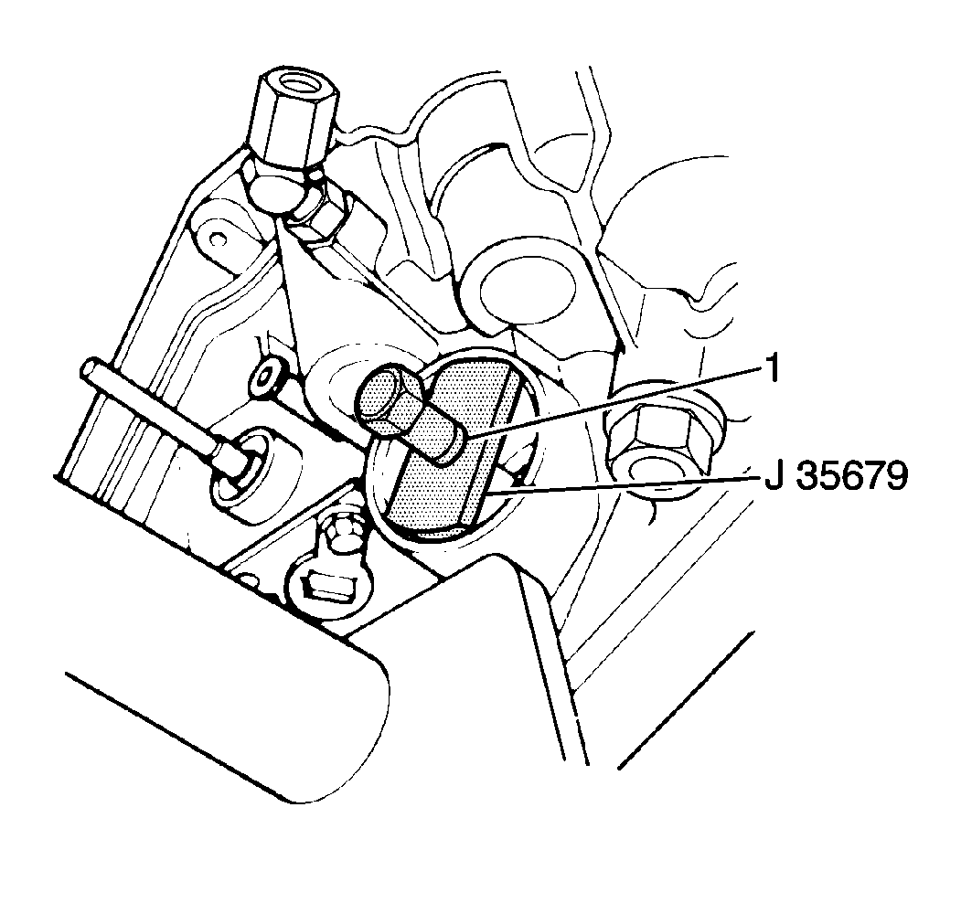
- Measure the brake apply
piston rod length using the following procedure:
| 77.1. | Install the J 35679
into the piston. |
| 77.2. | Observe the groove (1) on the plunger of the tool. |
| 77.3. | Firmly push the button of the tool. This pushes the brake apply
rod into the case. |
| 77.4. | If the groove is visible, the piston stroke is within the specified
range: 1.5-3.0 mm (0.059-0.118 in). |
| 77.5. | If the piston stroke exceeds the specified range, replace the
piston rod with a longer piston rod. |
| 77.6. | Select from the following piston rod lengths: |
| 77.7. | Measure the piston stroke again. |
If the piston stroke still exceeds the specified range, replace the
brake piston band.
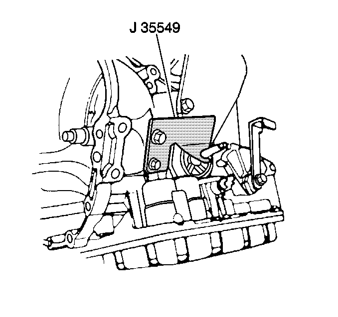
- Use the following procedure
in order to install the second coast brake piston:
| 78.1. | Remove the installed parts from the bore. |
| 78.2. | Install the outer spring with the piston. |
| 78.3. | Place the cover into the bore. |
| 78.4. | Use the J 35549
in order to install the snap ring while pressing the cover. |
- Inspect the operation of the second coast brake piston. Apply
compressed air into the hole with the case and verify that the piston rod
moves.
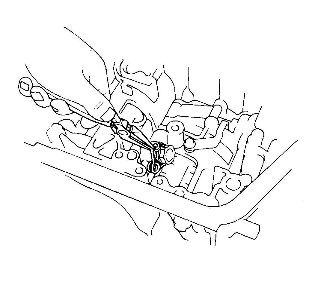
- Install the governor pressure
adapter into the case.
- Align the hole of the pressure adapter with the hole of the case.
- Install the torsion spring.
- Do not let the adapter slide. If the adapter slides, the spring
will fall out when pulled by hand.
- Install the manual valve lever and the manual valve shaft.
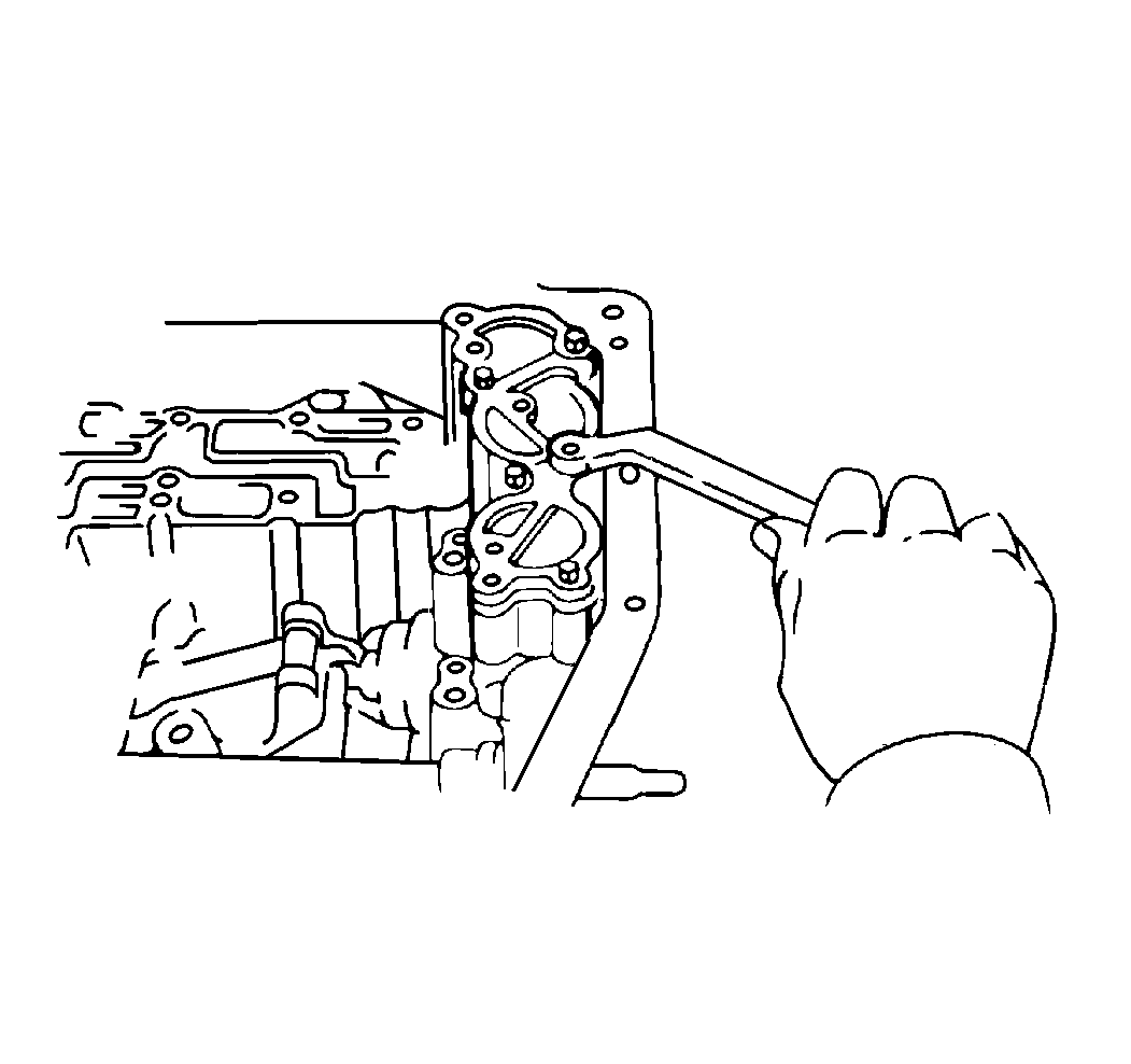
- Install the accumulator
springs and pistons into the bore. Place the cover with the gasket.
Tighten the bolts at small intervals in sequence.
For bolt lengths, refer to
Accumulator Spring Specifications
.
- Install the governor apply gasket.
- Install the governor oil strainer.
- Install the throttle cable by pushing the cable through the case.
Seat the cable fully.
Do NOT damage the O-ring.
- Place the valve body onto the transaxle.
While holding the cam down with your hand, slip the cable end into the
slot and lower the valve body into place.
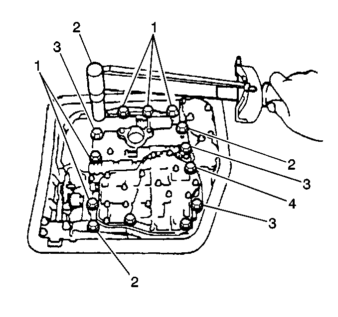
- Install the 14 bolts
into the valve body. Refer to
Valve Body Installation
.
The following are bolt lengths for the 14 valve body bolts as
shown in the figure:
Tighten
Tighten the valve body bolts to 10 N·m (89 lb in).
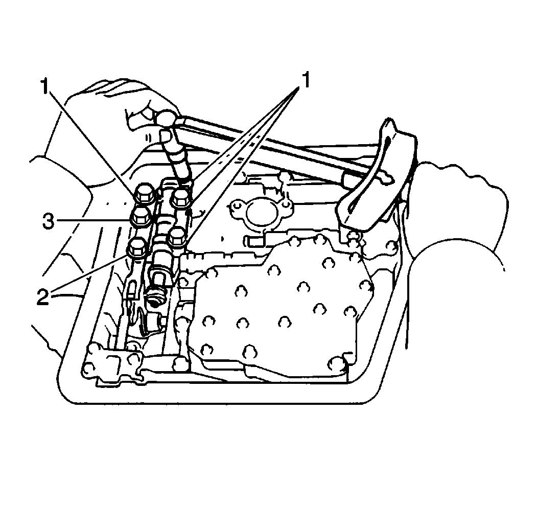
- Install the manual valve
onto the valve body.
Refer to
Valve Body Installation
.
The following are the lengths of the manual bolts as shown in the figure:
Tighten
Tighten the manual bolts to 10 N·m (89 lb in).
- Install the detent spring.
Tighten
Tighten the detent spring bolt to 10 N·m (89 lb in).
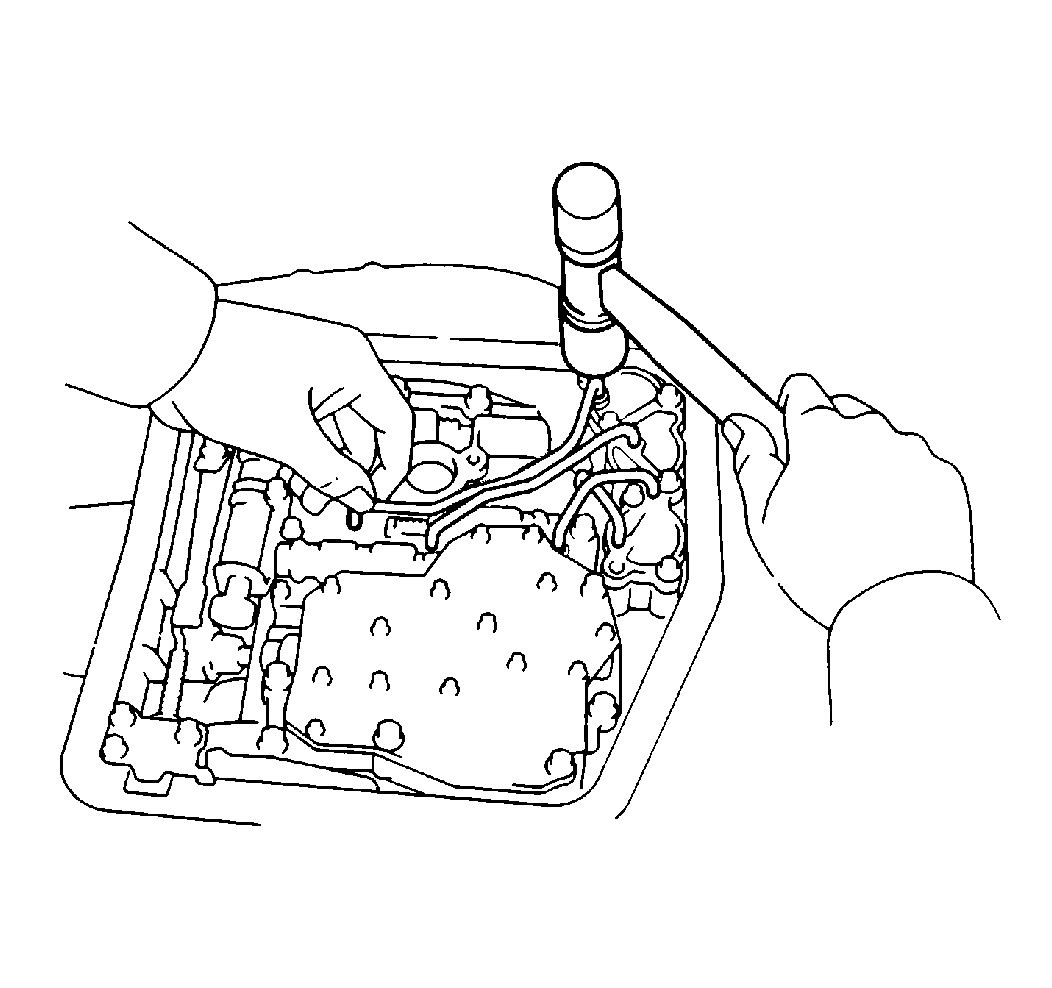
Important: Do not bend or damage the tube.
- Install the oil tubes.
- Install the tube retainer.
Tighten
Tighten the tube retainer bolts to 10 N·m (89 lb in).
- Install the oil strainer.
Tighten
Tighten the oil strainer bolts to 10 N·m (89 lb in).
Important: Place the magnet in a pan so that the magnet does not interfere with
the tubes.
- Install the magnet into place.
- Install the oil pan with a gasket.
Tighten
Tighten the oil pan bolts to 5.0 N·m (44 lb in).
- Use the following procedure in order to install the governor body.
| 98.1. | Install the governor body adapter. |
| 98.2. | Install the governor body with the plate washer. |
| 98.3. | Install the thrust washer onto the governor body. |
| 98.4. | Install the cover over a new O-ring. |
| 98.5. | Install the cover bracket with two bolts. |
- Install the throttle cable retaining plate.
- Install the tube and filler gage.
- Use the following procedure in order to install the PNP switch:
| 101.1. | Install a new seal gasket so that the lip faces inward. |
| 101.2. | Install a lock washer and a nut. |
Tighten
Tighten the nut to 7.0 N·m (62 lb in).
- Stake the nut with a lock washer.
- Install the manual shift lever.
- Use the following procedure in order to adjust the PNP switch:
| 104.1. | Connect an ohmmeter between the terminals. |
| 104.2. | Shift the lever to the N position. |
| 104.3. | Adjust the PNP switch to the point where there is continuity between
the terminals. |
| 104.4. | Lock the PNP switch with 2 bolts. |
Tighten
Tighten the PNP switch mounting bolts to 5.5 N·m (49 lb in).
- Use the following procedure in order to install the 2 oil
cooler pipes:
| 105.1. | Install the bracket onto the case. |
| 105.2. | Connect the pipes to the union. |
| 105.3. | Clamp the 2 pipes onto the bracket. |
Tighten
Tighten the union nuts to 34 N·m (25 lb ft).


