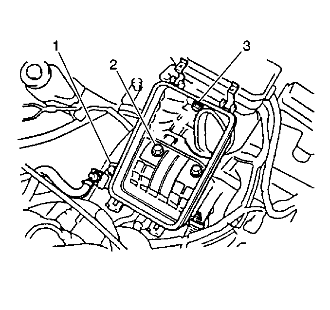
- Install the engine hoist.
- Remove the engine assembly from the J 36854
.
Notice: Apply the proper amount of the sealant to the fastener when assembling
this component. Excessive use of the sealant can prohibit the component from
being assembled properly or allow the fastener to loosen. A component or fastener
that is not assembled properly can loosen or fall off leading to extensive
engine damage.
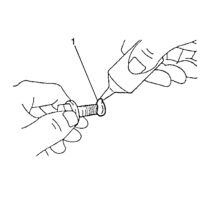
- Apply GM P/N 12345493,
or the equivalent, to the flywheel retaining bolt threads (1).
Notice: Use the correct fastener in the correct location. Replacement fasteners
must be the correct part number for that application. Fasteners requiring
replacement or fasteners requiring the use of thread locking compound or sealant
are identified in the service procedure. Do not use paints, lubricants, or
corrosion inhibitors on fasteners or fastener joint surfaces unless specified.
These coatings affect fastener torque and joint clamping force and may damage
the fastener. Use the correct tightening sequence and specifications when
installing fasteners in order to avoid damage to parts and systems.
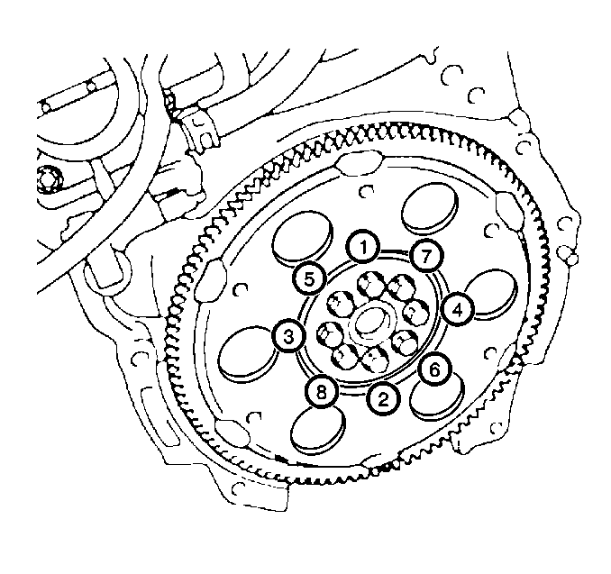
- For vehicles equipped with an Automatic Transmission, install the flywheel
retaining bolts (1-8) to the crankshaft.
Tighten
Tighten the eight flywheel retaining bolts in sequence for Automatic
Transmission to 83 N·m (61 lb ft).
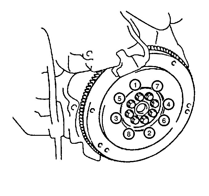
- For vehicles equipped
with a Manual Transmission, install the flywheel retaining bolts to the crankshaft.
Tighten
Tighten the eight flywheel retaining bolts in sequence for Manual Transmission
to 49 N·m (36 lb ft). After the proper torque
has been reached, use a J 36660-A
and tighten the flywheel bolts an additional 90 degrees.
- For vehicles equipped with manual transmission, install the following
items. Refer to
Clutch Assembly Replacement
in Clutch:
| • | The pressure plate assembly |
- Install the engine assembly. Lower the engine into the engine
compartment while ensuring clearance on all sides.
- Install the two upper transmission to engine mounting bolts.
- Install the four lower transmission to engine mounting bolts.
Tighten
Tighten the transmission to engine mounting bolts to 64 N·m
(47 lb ft).
- Install the right side engine mounting bracket.
Tighten
Tighten the engine mounting bracket bolts to 54 N·m (40 lb ft).
- Use the three engine mounting bracket bolts in order to secure
the right side engine mounting bracket.
Tighten
Tighten right-side engine mount-to-engine bracket bolts to 54 N·m
(40 lb ft).
- Install the right side engine mount.
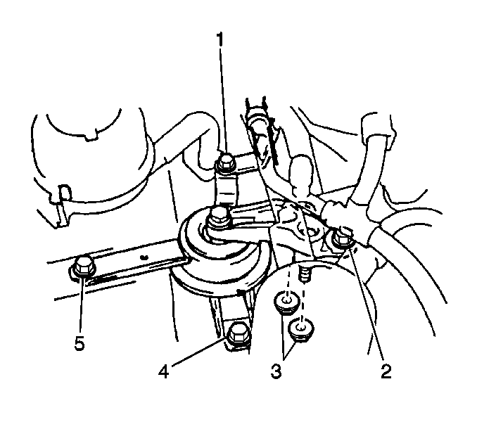
- Use the two nuts (3) and
the four bolts (1, 2, 4, 5) in order to secure the right
side mounting insulator.
Tighten
Tighten the right side engine mount bolts and nuts to 54 N·m
(40 lb ft).
- Remove the engine hoist.
Notice: Apply the proper amount of the sealant to the fastener when assembling
this component. Excessive use of the sealant can prohibit the component from
being assembled properly or allow the fastener to loosen. A component or fastener
that is not assembled properly can loosen or fall off leading to extensive
engine damage.
- Raise and support the vehicle.
- Install the four lower transmission to engine mounting bolts.
Tighten
Tighten the four lower transmission to engine mounting bolts to 67 N·m
(49 lb ft).
- Install the axle shaft heat shield.
- Use the one nut and two bolts in order to secure the axle shaft
heat shield.
Tighten
| • | Tighten the axle shaft heat shield nut to 18 N·m
(13 lb ft). |
| • | Tighten the axle shaft heat shield bolts to 18 N·m
(13 lb ft). |
- Install the right side drive axle. Refer to
Wheel Drive Shaft Replacement
in Wheel Drive Shafts.
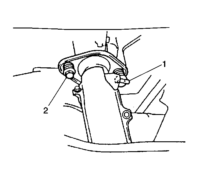
- Install the exhaust pipe
to the exhaust manifold.
- Use the two bolts and the springs (1, 2) in order to secure the
exhaust pipe to the exhaust manifold.
Tighten
Tighten the exhaust pipe flange bolts to 62 N·m (46 lb ft).
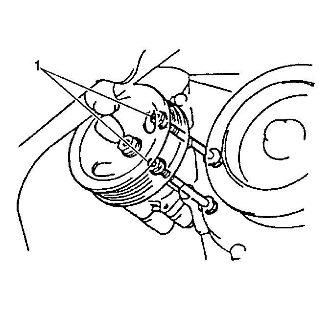
- Position the power steering
pump at the mounting location.
- Use the two bolts (1) and the nuts in order to secure the power
steering pump.
Tighten
Tighten the power steering pump mounting bolts to 37 N·m
(27 lb ft).
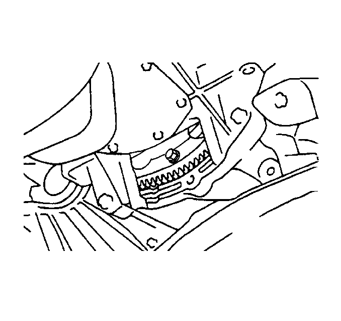
- If the vehicle is equipped
with an automatic transmission, install the six torque converter bolts.
Tighten
Tighten the six torque converter bolts to 35 N·m (26 lb ft).
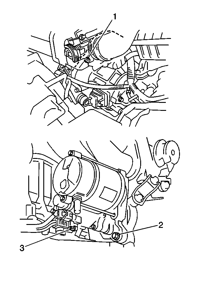
- Install the starter.
- Use the starter bolts (1, 2) in order to secure the starter.
Tighten
Tighten the starter bolts to 30 N·m (22 lb ft).
- Connect the starter motor electrical connections.
- Install the left side lower engine splash shield.
- Use the six bolts in order to secure the left side lower engine
splash shield.
Tighten
Tighten the left side engine splash shield bolts to 10 N·m
(89 lb in).
- Install the right side lower engine splash shield.
- Use the six bolts in order to secure the right side lower engine
splash shield.
Tighten
Tighten the right side engine splash shield bolts to 10 N·m
(89 lb in).
- Lower the vehicle.
- Install the upper starter bolt.
Tighten
Tighten the upper starter bolt to 30 N·m (22 lb ft).
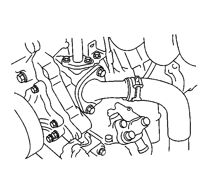
- Install the lower radiator
hose to the thermostat housing.
- Reroute the engine harness. Reposition the engine harness as necessary.
- Install the engine wiring harness brackets.
- Use the engine wiring harness bracket bolts in order to secure
the engine wiring harness.
- Install the following items:
| • | The oxygen sensor gasket |
- Use the two oxygen sensor nuts in order to secure the oxygen sensor.
Tighten
Tighten the oxygen sensor nuts to 44 N·m (32 lb ft).
- Connect the oxygen sensor connector.
- Connect all necessary electrical connectors.
- Connect all necessary hoses.
- Install the ground wire to the engine mount bracket.
- Use the one ground wire bolt in order to secure the ground wire
to the engine mount bracket.
Tighten
Tighten the one ground wire bolt to 15 N·m (11 lb ft).
- Install the upper generator mounting bolt.
Tighten
Tighten the upper generator mounting bolt to 23 N·m (17 lb ft).
- Remove the cap from the washer pump outlet.
- Connect the washer pump fluid line to the washer fluid tank.
- Connect the washer pump electrical connector.
- Install the washer fluid tank.
- Use the one washer fluid tank bolt in order to secure the washer
fluid tank.
Tighten
Tighten the washer fluid reservoir mounting bolt to 10 N·m
(89 lb in).
- Install the upper radiator hose.
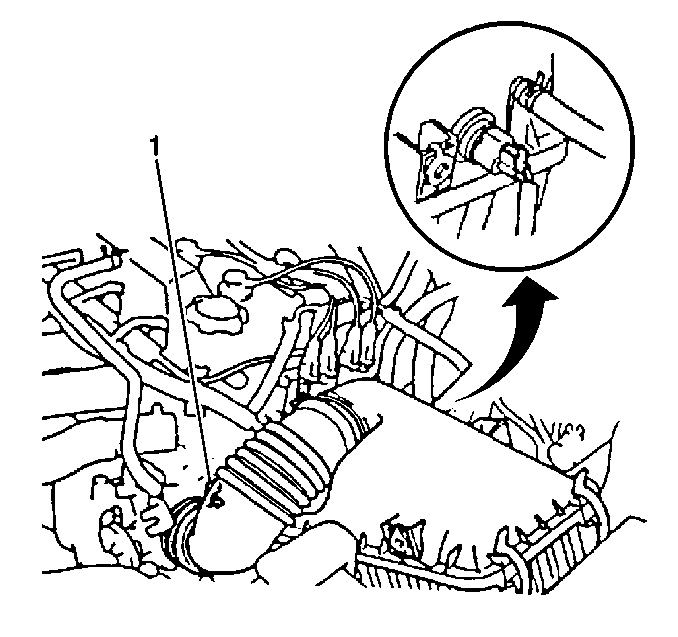
- Install the air cleaner
lower box.
- Use the three air cleaner lower box bolts in order to secure the
air cleaner lower box.
- Install the air filter.
- Install the vacuum switching valve (VSV) bracket to the air cleaner
case.
- Use the one VSV bracket bolt in order to secure the VSV bracket.
- Connect the two wiring harness retainer clips to the air cleaner
lower case.
- Install the air cleaner hose and cap assembly (1).
- Connect the intake air temperature (IAT) sensor.
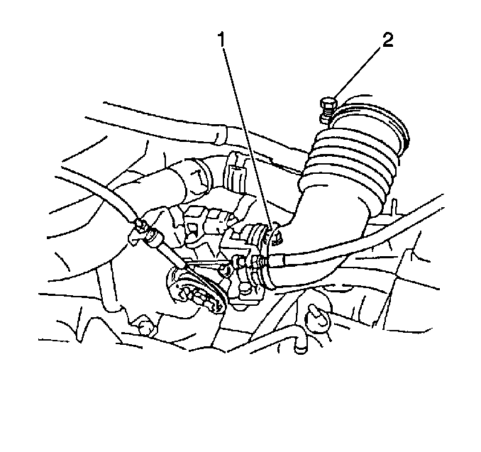
- For vehicles equipped
with automatic transmission, install the following components:
| • | The transmission TV cable to the accelerator cable bracket |
| • | The transmission TV cable to the throttle body |
- Install the accelerator cable to the accelerator cable bracket.
- Install the accelerator cable to the throttle body (1).
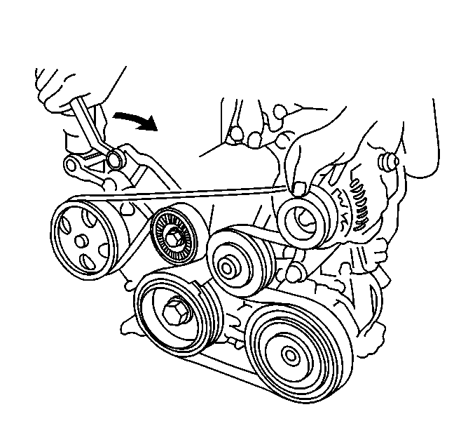
- Install the serpentine
drive belt. Refer to
Drive Belt Replacement
.
- If vehicle is equipped with A/C, install the A/C compressor. Refer
to
Air Conditioning Compressor Replacement
in Heating,
Ventilation and Air Conditioning.
- If vehicle is equipped with a manual transmission, install the
following components:
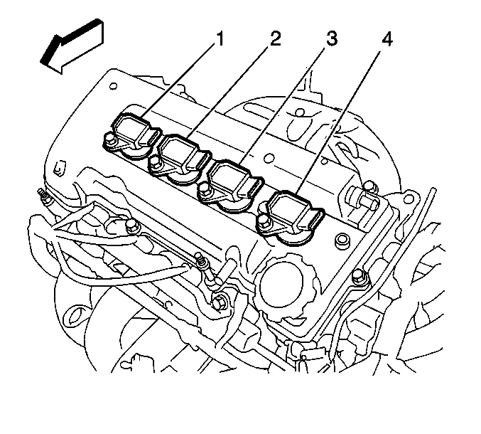
- Install the four ignition
coils (1, 2, 3, 4).
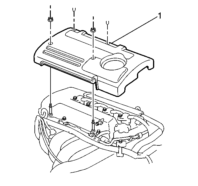
- Install the engine cover (1).
- Install the hood. Refer to
Hood Replacement
in Body and Accessories.
- Connect the windshield washer hose at the hood.
- Fill the engine oil.
- Fill the cooling system.
Caution: Unless directed otherwise, the ignition and start switch must be in the OFF or LOCK position, and all electrical loads must be OFF before servicing
any electrical component. Disconnect the negative battery cable to prevent an electrical spark should a tool or equipment come in contact with an exposed electrical terminal. Failure to follow these precautions may result in personal injury and/or damage to
the vehicle or its components.
- Connect the negative battery cable to the battery.
Tighten
Tighten the battery cable bolt to 15 N·m (11 lb ft).


