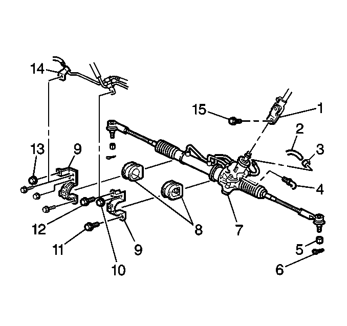
- Install the 2
insulators (8) to the steering gear.
- Place the steering gear in the vehicle using the following process:
| 2.1. | From the LH side of the vehicle, raise and move the steering gear
toward the RH side of the vehicle. |
| 2.2. | Move the steering gear toward the LH side of the vehicle. |
Notice: Use the correct fastener in the correct location. Replacement fasteners
must be the correct part number for that application. Fasteners requiring
replacement or fasteners requiring the use of thread locking compound or sealant
are identified in the service procedure. Do not use paints, lubricants, or
corrosion inhibitors on fasteners or fastener joint surfaces unless specified.
These coatings affect fastener torque and joint clamping force and may damage
the fastener. Use the correct tightening sequence and specifications when
installing fasteners in order to avoid damage to parts and systems.
- Install the following
components to the steering gear:
| • | The 2 steering gear clamps (9) |
| • | The 2 steering gear clamp bolts (11) |
| • | The 2 steering gear clamp nuts (10) |
Tighten
Tighten the steering gear clamp bolts and nuts to 71 N·m
(52 lb ft).
- Install the steering gear boot heat shield. Secure with 1 bolt
and 1 nut.
Tighten
Tighten the steering gear boot heat shield bolt and nut to 5.4 N·m
(48 lb in).
- Install the exhaust pipe and the gasket to the exhaust manifold.
Secure with the 2 exhaust pipe springs and the 2 exhaust pipe bolts.
Tighten
Tighten the exhaust pipe bolts to 62 N·m (46 lb ft).
- Install the rear transaxle mount bracket. Secure with 3 bolts.
Tighten
Tighten the bolts to 77 N·m (57 lb ft).
- Install the rear transaxle mount. Secure with the through bolt.
Tighten
Tighten the rear transaxle mount through bolt to 87 N·m
(64 lb ft).
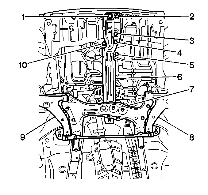
- Install the front suspension crossmember (7), the trans support (6),
the 2 control arms (8, 9), and the stabilizer shaft together
as a unit. Refer to
Front Suspension Crossmember Replacement
in Front Suspension.
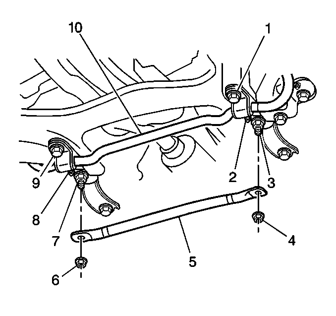
- Install the front suspension
brace (5). Secure with 2 nuts (4, 6).
Tighten
Tighten the nuts to 69 N·m (51 lb ft).
- Install the outer tie rod. Refer to
Rack and Pinion Outer Tie Rod End Replacement
.
- Install the front tire and wheel assemblies. Refer to
Tire and Wheel Removal and Installation
in Tires
and Wheels.
- Install the exhaust manifold pipe drive shaft heat shield. Secure
with 1 nut and 2 bolts.
Tighten
Tighten the nut and bolt to 5.4 N·m (48 lb in).
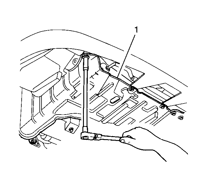
- Install the LH lower engine
splash shield. Secure with 6 bolts
Tighten
Tighten the engine splash shield bolts to 10 N·m (89 lb in).
- Install the RH lower engine splash shield (1). Secure with
6 bolts
Tighten
Tighten the engine splash shield bolts to 10 N·m (89 lb in).
- Lower the vehicle.
- Remove the Engine Support Fixture. Refer to
Engine Support Fixture
in Engine Mechanical - 1.8 L.
- Install the oxygen sensor gasket and the oxygen sensor. Refer
to
Heated Oxygen Sensor 1 Replacement
in Engine Controls.

Notice: The inlet and outlet hoses must not be twisted during installation.
Do not bend or distort the inlet or outlet hoses to make installation easier.
Failure to follow these procedures could result in component damage.
- Connect the steering gear outlet pipe (2) to the
steering gear. Secure with one nut.
Tighten
Tighten the nut to 13 N·m (108 lb in).
- Connect the steering gear inlet pipe (4) to the steering
gear. Secure with one nut.
Tighten
Tighten the nut to 13 N·m (108 lb in).
- Install the following components:
| 20.1. | The LH steering gear inlet and outlet pipe clip (14) |
| 20.2. | The RH steering gear outlet pipe clip bolt |
| 20.3. | The LH steering gear inlet and outlet pipe clip bolt (12) |
Tighten
Tighten the bolts to 5.4 N·m (48 lb in).
- Install the following components:
| • | The outlet pipe heat shield |
| • | The outlet pipe heat shield bolt |
Tighten
Tighten the bolt to 5.4 N·m (48 lb in).
- Install the steering shaft lower coupling bolt (15).
Tighten
Tighten the bolt to 35 N·m (26 lb ft).
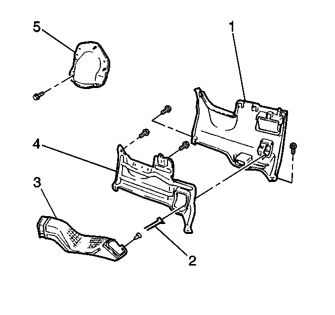
- Install the steering column
upper cover (5). Secure with 5 bolts.
Tighten
Tighten the bolts to 4.9 N·m (43 lb in).
Notice: When adding fluid or making a complete fluid change, always use the
proper power steering fluid. Failure to use the proper fluid will cause hose
and seal damage and fluid leaks.
- Fill the power steering fluid reservoir. Refer to
Checking and Adding Power Steering Fluid
.
Notice: If the power steering system has been serviced, an accurate fluid level
reading cannot be obtained unless air is bled from the steering system. The
air in the fluid may cause pump cavitation noise and may cause pump damage
over a period of time.
- Bleed the power steering system. Refer to
Power Steering System Bleeding
.
- Measure the wheel alignment. Adjust as necessary. Refer to
Wheel Alignment Measurement
in Wheel Alignment.


