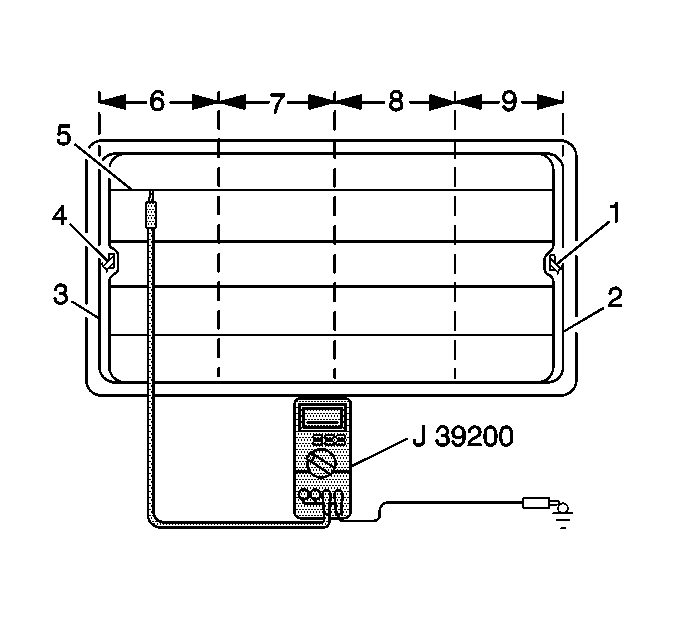
Tools Required
J 39200 Digital Multimeter
The optional rear window defogger system consists of the
following components:
| • | A rear window defogger switch |
| • | A rear window equipped with the following components imbedded
on the inside surface: |
| - | A number of horizontal ceramic silver compound element lines (5) |
| - | Two vertical bus bars (2,3) |
The feed terminal is soldered to the bus bar on the right side (1).
The ground terminal is soldered to the bus bar on the left side (4).
Testing Grid Lines
Use the following procedure in order to locate inoperative grid lines:

- Start the engine.
- Turn the rear window defogger system ON.
- Ground the negative lead of the J 39200
.
- Lightly touch the positive lead of the J 39200
to each grid line. The voltage will decrease as you move the
lead farther away from the feed bus bar.
- If the J 39200
reads a high voltage at both ends of the grid lines, inspect for the following
conditions:
| • | A loose terminal-to-bus bar connection |
| • | A loose ground wire-to-body connection |
- Test all the grid lines in at least two places in order to eliminate
the possibility of bridging a break. For best results, contact each grid line
a few millimeters on either side of the window centerline.
- If an abnormal meter reading is apparent on a specific grid line,
perform the following steps:
| 7.1. | Place the lead on the grid. |
| 7.2. | Move the lead along the grid until the voltage reading drops significantly.
This condition indicates a break in the continuity of the grid line. |
| 7.3. | Mark the grid line breaks on the outside of the window using a
wax pencil or a crayon. Refer to
Grid Line Repair
. |

