| • | J 22610 Service Boot Clamp Installer |
| • | J 35566 Seal Clamp Tool |
| • | J 22912-B Bearing Puller |
Disassembly Procedure
- Remove the wheel drive shaft. Refer to Wheel Drive Shaft Replacement .
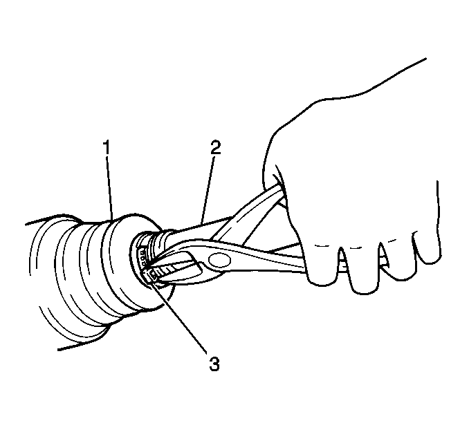
- Remove the outer joint boot clamps (3).
- Slide the outer joint boot (1) towards the center of the wheel drive shaft.
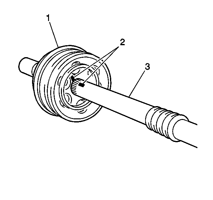
- Place index marks (2) on the outer joint and the wheel drive shaft.
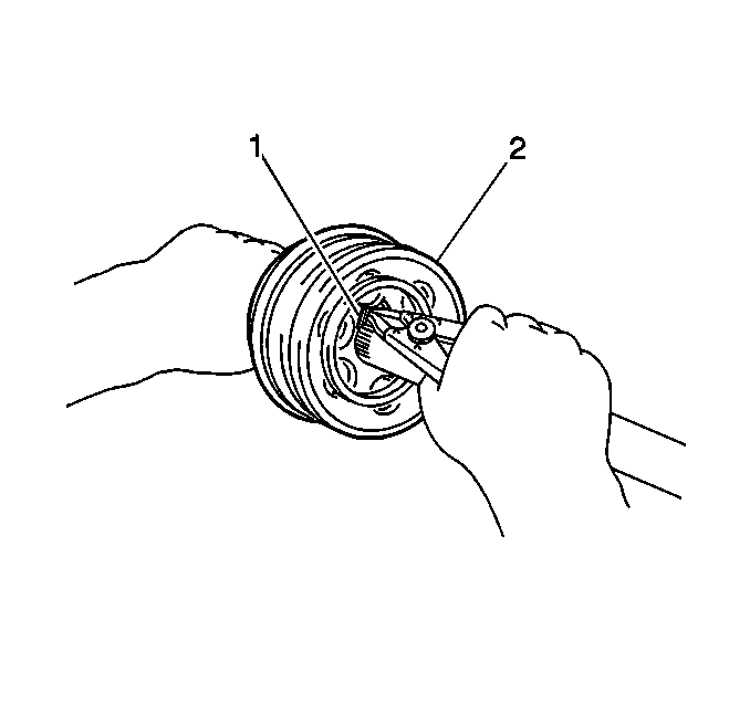
- Remove the outer joint (2) from the wheel drive shaft by expanding the snap ring (1) and pulling outward on the joint.
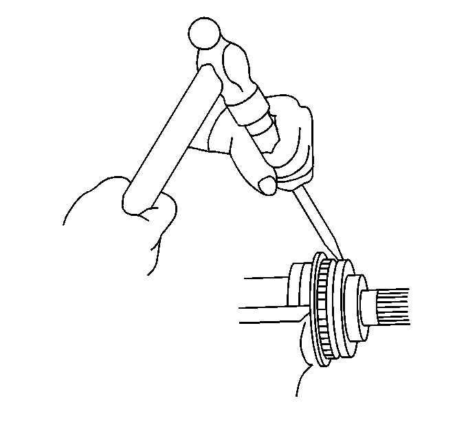
- Mount the wheel drive shaft in a soft jaw vise. Remove the outer joint seal.
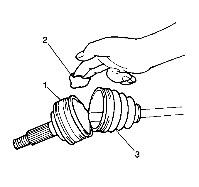
- Clean the outer boot with a clean, dry, solvent free cloth.
- Inspect the outer boot for tears damage or fatigue. Replace as necessary.
- Inspect the outer joint for excessive wear or damage. If any excessive wear, damage or abnormality is found, replace the outer joint as an assembly.
- Inspect the dynamic dampener on the right wheel drive shaft for damage or distortion. Replace as necessary.
Notice: When servicing the wheel drive shaft(s), place reference marks on all components to ensure that all components are reassembled in the correct position. If the components are not reassembled in the correct position, premature wear of the joint and/or excessive driveline vibrations may occur.
Notice: Do not clean the wheel drive shaft boot(s) in solvent. Cleaning the wheel drive shaft boot(s) in degreaser or other solvents can cause the boot(s) to deteriorate. Use only a clean, dry, solvent-free cloth to clean the wheel drive shaft boot(s).
Important: Do not disassemble the outer joint. If any abnormality is found in the joint, or in the joint components, replace the joint as an assembly.
Notice: When servicing the hub assembly, be careful not to damage the ABS components. If any of the ABS components are damaged, the ABS system may not function properly and the damaged component will need to be replaced.
Assembly Procedure
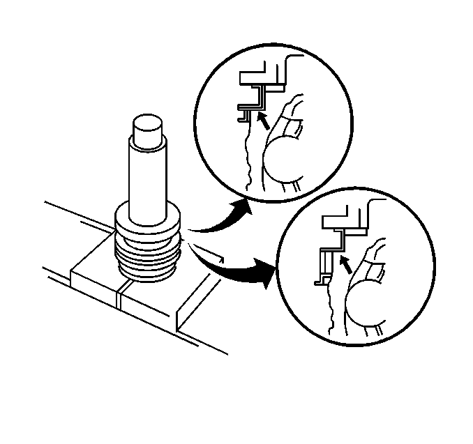
- Install the outer joint seal using a suitable sleeve and a press.
- If the damper was removed, install the damper to the wheel drive shaft before installing the outer joint.
- Install the damper assembly (right side wheel drive shaft only) to the wheel drive shaft.
- The damper should be located on the groove on the wheel drive shaft.
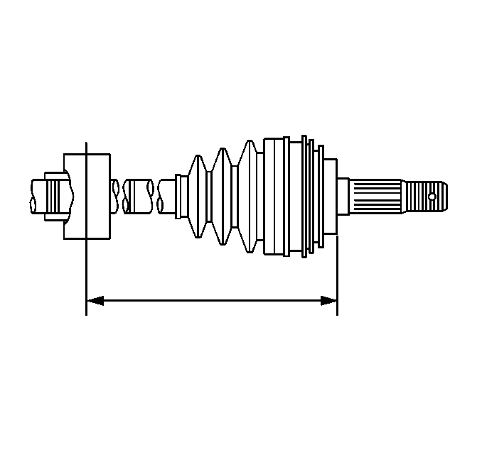
- The damper centerline should be 431.3 mm (16.980 in), plus or minus 3.0 mm (0.118 in) from the outer joint. Crimp the damper clamp using the J 22610 .
- Install the outer boot and clamps to the wheel drive shaft. Do not crimp the clamps at this time.
- Align the index marks (2) on the outer joint and the wheel drive shaft.
- Expand the snap ring (1) and slide the outer joint onto the wheel drive shaft.
- Pack the outer joint (1) with 165-185 grams (5.8-6.4 oz) of grease (green) supplied with outer joint boot kit.
- Install the outer joint large boot clamp using the J 22610 .
- Measure the wheel drive shaft length (1) to ensure that the boots are not stretched or excessively contracted when the wheel drive shaft is at standard length.
- Crimp the clamp (2) using the J 35566 .
- Check the boots for distortion or dents. Correct as necessary.
- Install the wheel drive shaft. Refer to Wheel Drive Shaft Replacement .
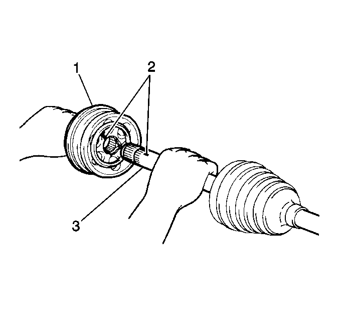

Important: Make sure the snap ring is securely seated in the groove in the wheel drive shaft.
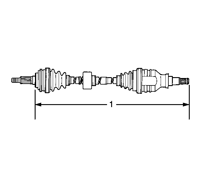
| • | Right wheel drive shaft standard length is 857.4 mm (33.756 in), plus or minus 5.0 mm (0.197 in). |
| • | Left wheel drive shaft standard length is 540.2 mm (21.268 in), plus or minus 5.0 mm (0.197 in). |
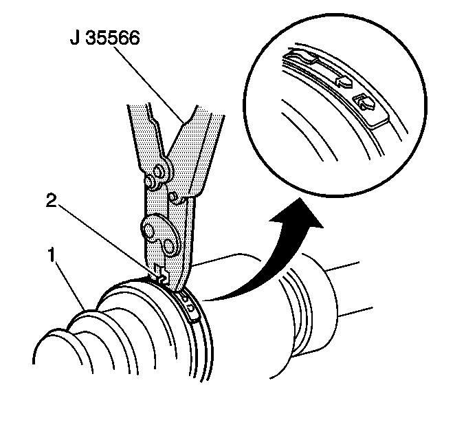
Important: Use the J 35566 to draw the closing hooks of the clamp together, so that the clamp locks into position.
