For 1990-2009 cars only
Removal Procedure
- Disable the SIR system. Refer to SIR Disabling and Enabling in SIR.
- Disconnect the negative battery cable. Refer to Battery Negative Cable Disconnection and Connection in Engine Electrical.
- Remove all related panels and components including the end gate. Refer to Endgate Replacement in Body Rear End.
- Repair as much of the damage as possible to factory specifications. Refer to the Rear Compartment section of Dimensions - Body .
- Loosen all mounting bolts that secure the body to the frame. Remove all of the bolts EXCEPT the 2 in the front tie bar and the 2 bolts under the front hinge pillar. Refer to Frame Cushion or Insulator Replacement in Frame and Underbody.
- Lift the rear of the body approximately 15 cm (6 in) off of the frame onto a wooden block as shown.
- Note the location and remove the sealers and anti-corrosion materials from the repair area, as necessary. Refer to Anti-Corrosion Treatment and Repair in Paint and Coatings.
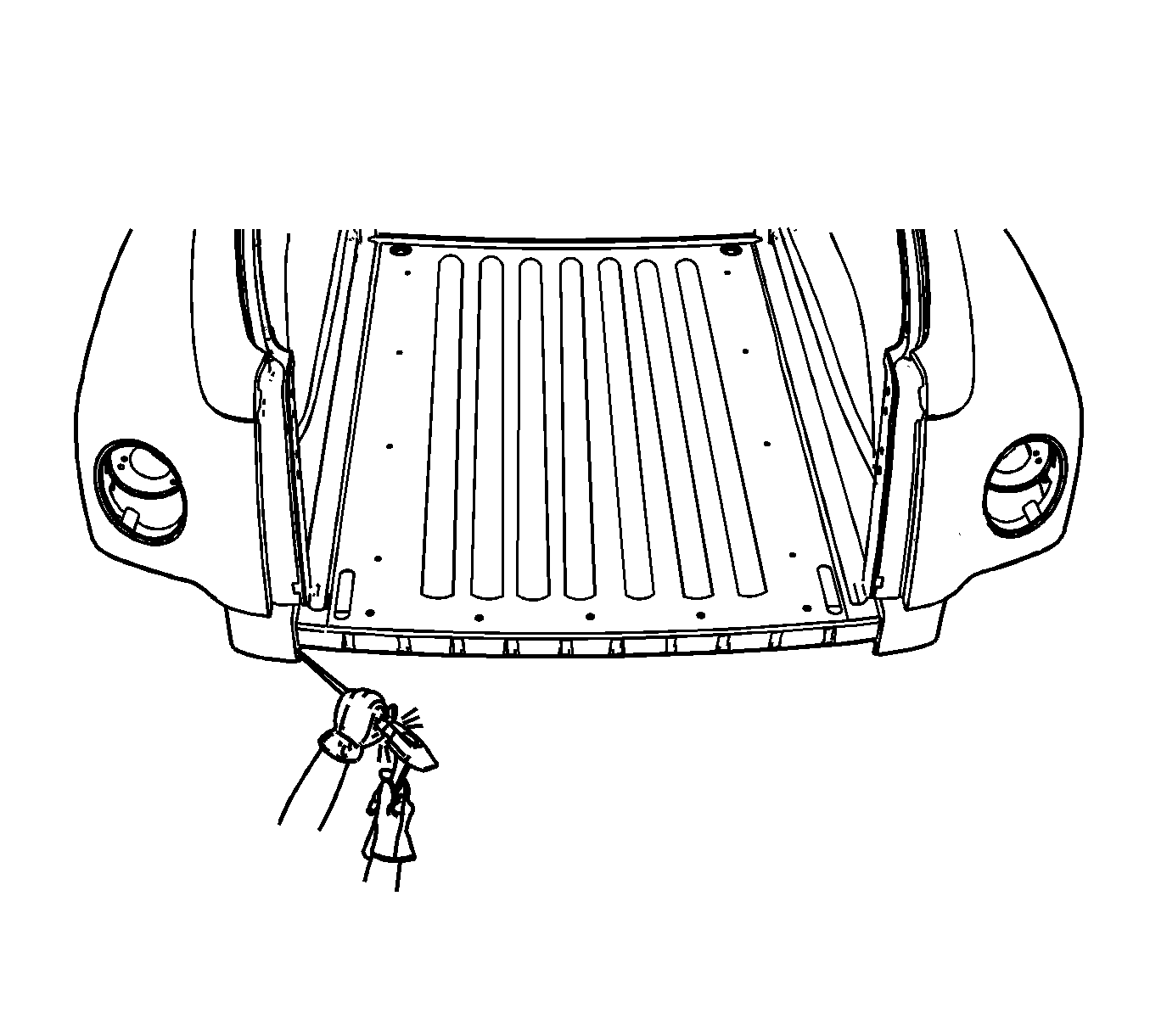
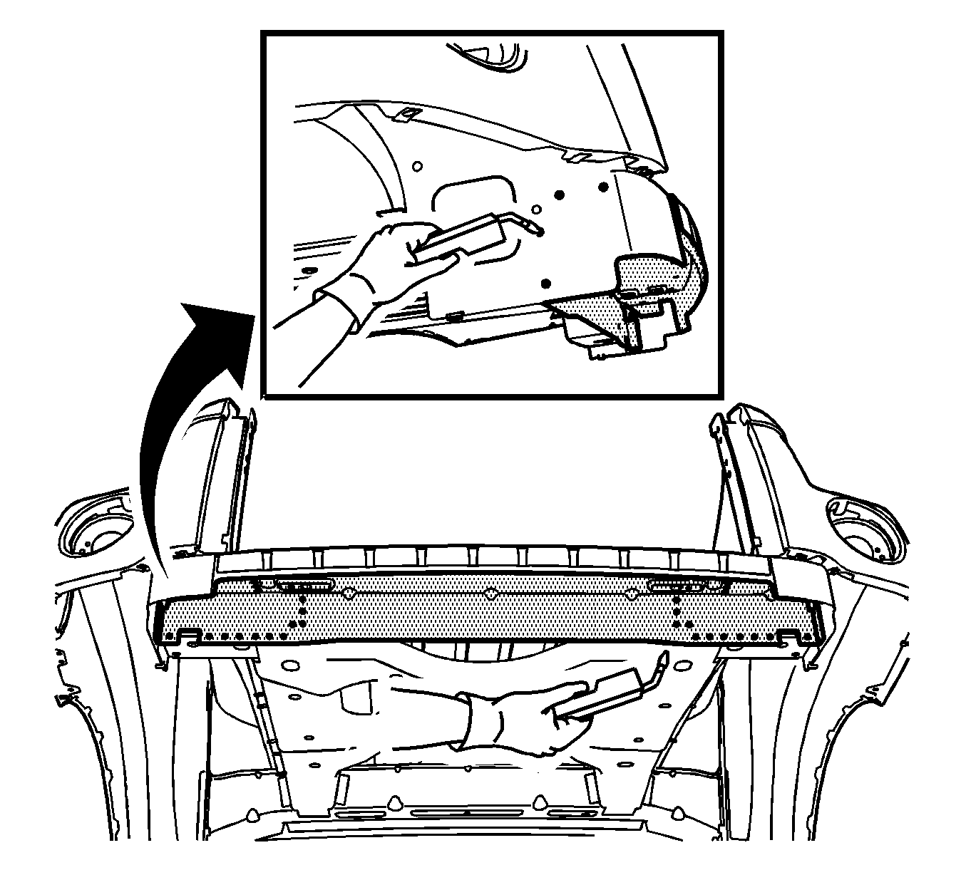
- Locate and drill out all of the factory welds in the underbody. Drill completely through all of the layers of metal.
- Locate and drill out all factory welds in the rear compartment floor. Drill completely through all of the layers of metal.
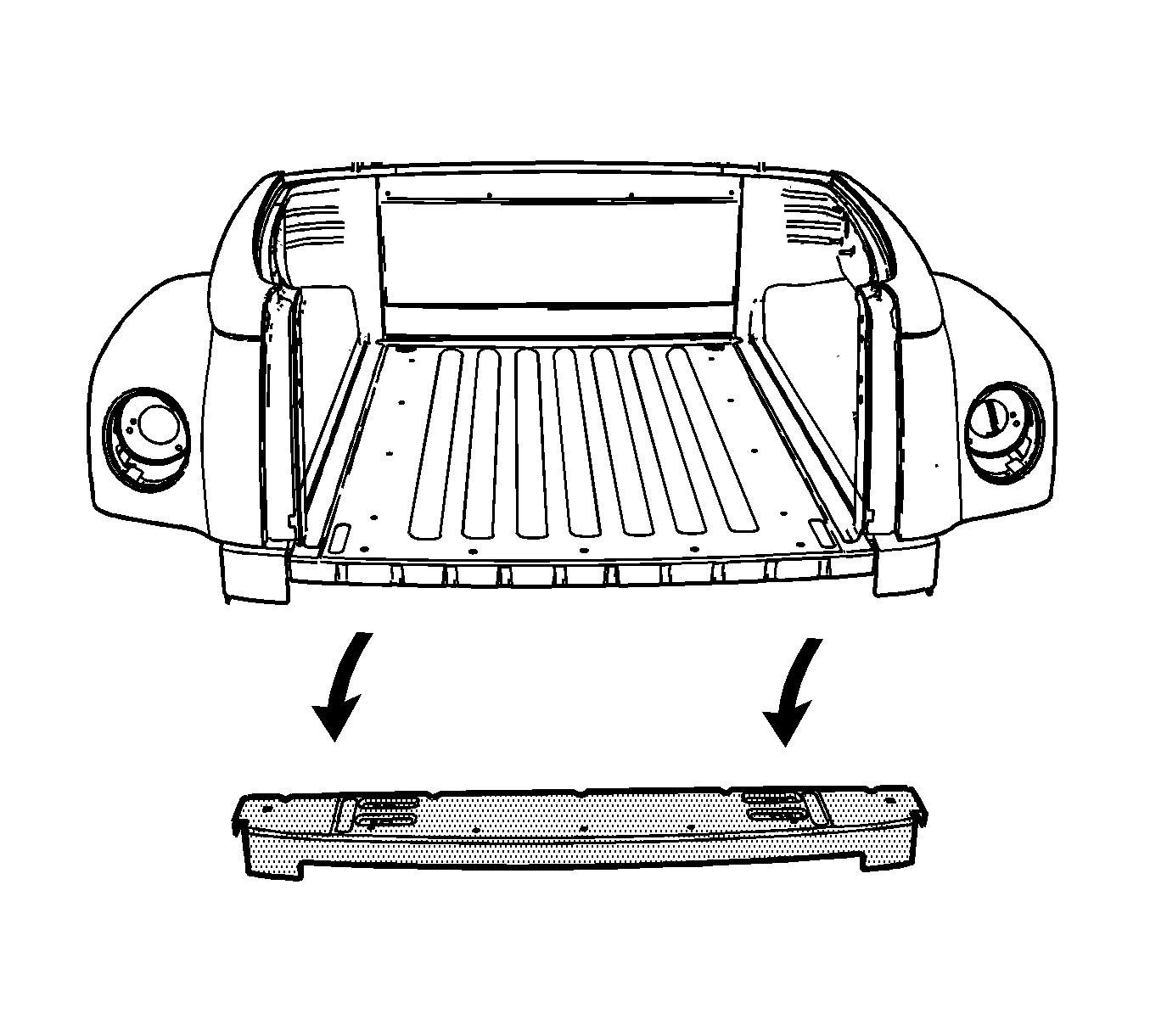
- Verify the existence of structural weld-through adhesive. Refer to Structure Adhesive Identification . If necessary use a chisel to separate the crossbar from the adjacent panels.
- Remove the damaged cross bar.
Caution: Refer to Approved Equipment for Collision Repair Caution in the Preface section.
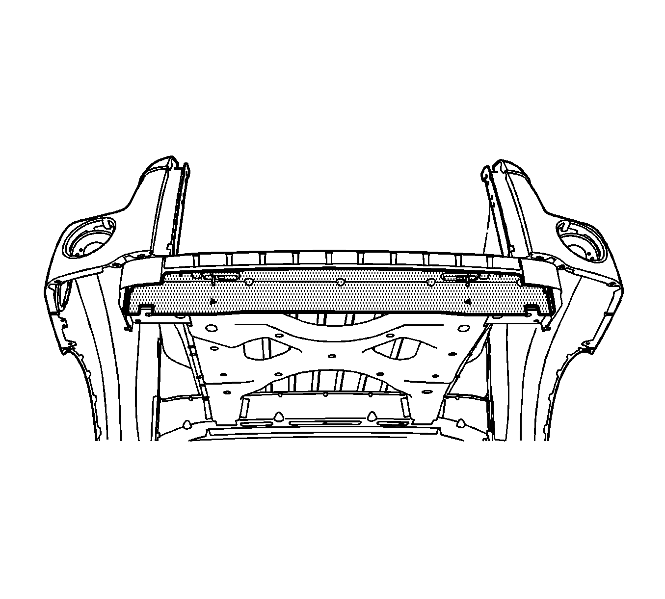
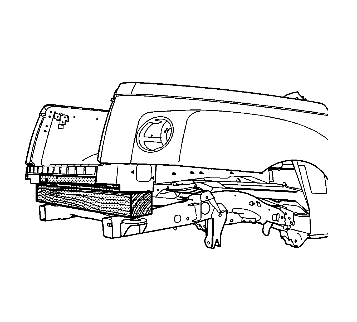
Important: Note the location and remove or disconnect any component that could be damaged while raising the rear portion of the body off of the frame.
Caution: Refer to Foam Sound Deadeners Caution in the Preface section.
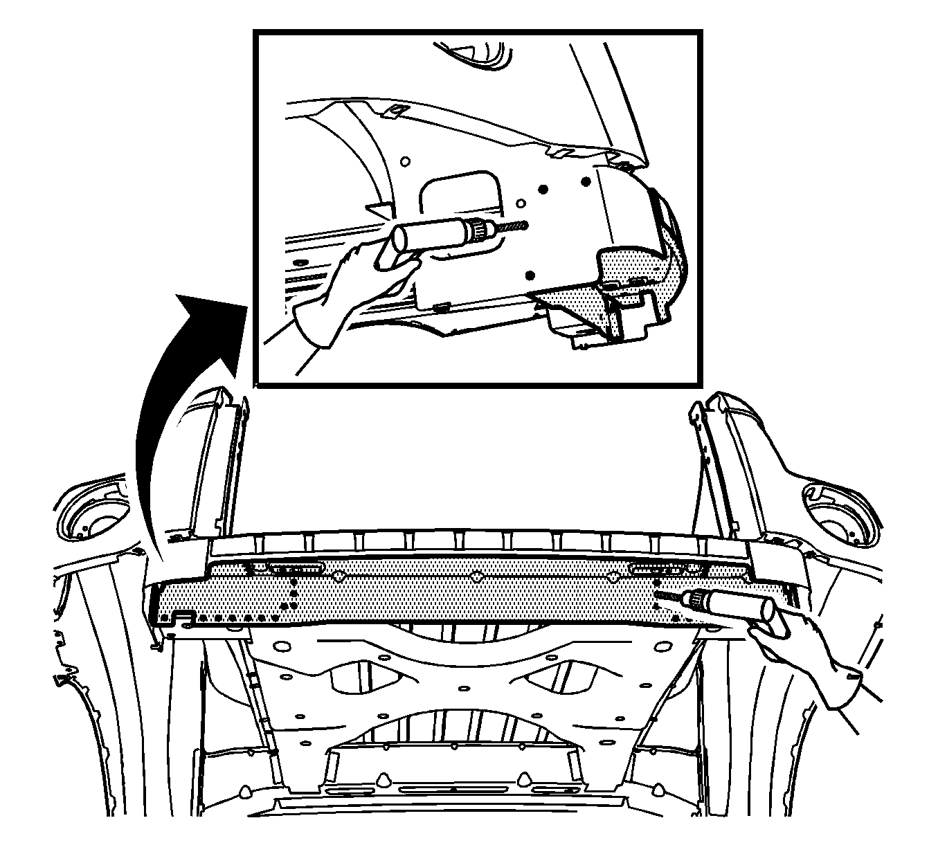
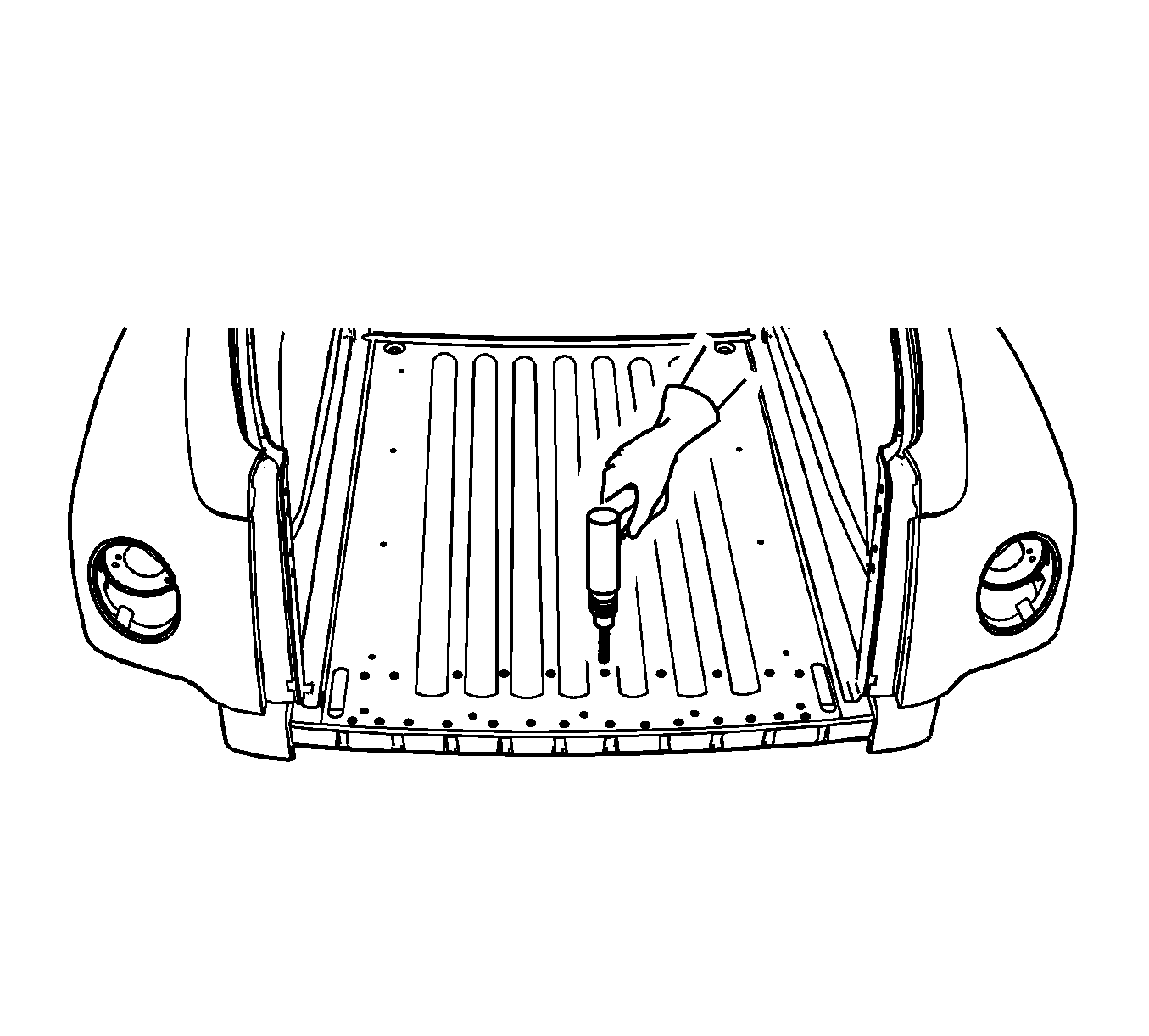
Installation Procedure
- Prepare all attachment surfaces as necessary.
- Apply 3M® Weld-Thru Coating P/N 05916 or equivalent to all mating surfaces.
- Replace the structural adhesive with an additional plug weld between the existing plug welds, if necessary.
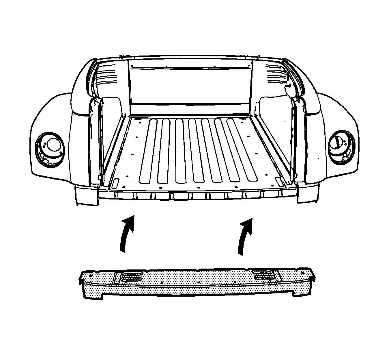
- Position the service part.
- Plug weld accordingly.
- Clean and prepare all welded surfaces.
- Apply the sealers and the anti-corrosion materials to the repair area, as necessary. Refer to Anti-Corrosion Treatment and Repair in Paint and Coatings.
- Paint the repair area. Refer to Basecoat/Clearcoat Paint Systems in Paint and Coatings.
- Lower the body to the frame and reattach the mounting bolts.
- Install all related panels including the end gate. Refer to Endgate Replacement in Body Rear End.
- Connect the negative battery cable. Refer to Battery Negative Cable Disconnection and Connection in Engine Electrical.
- Enable the SIR system. Refer to SIR Disabling and Enabling in SIR.
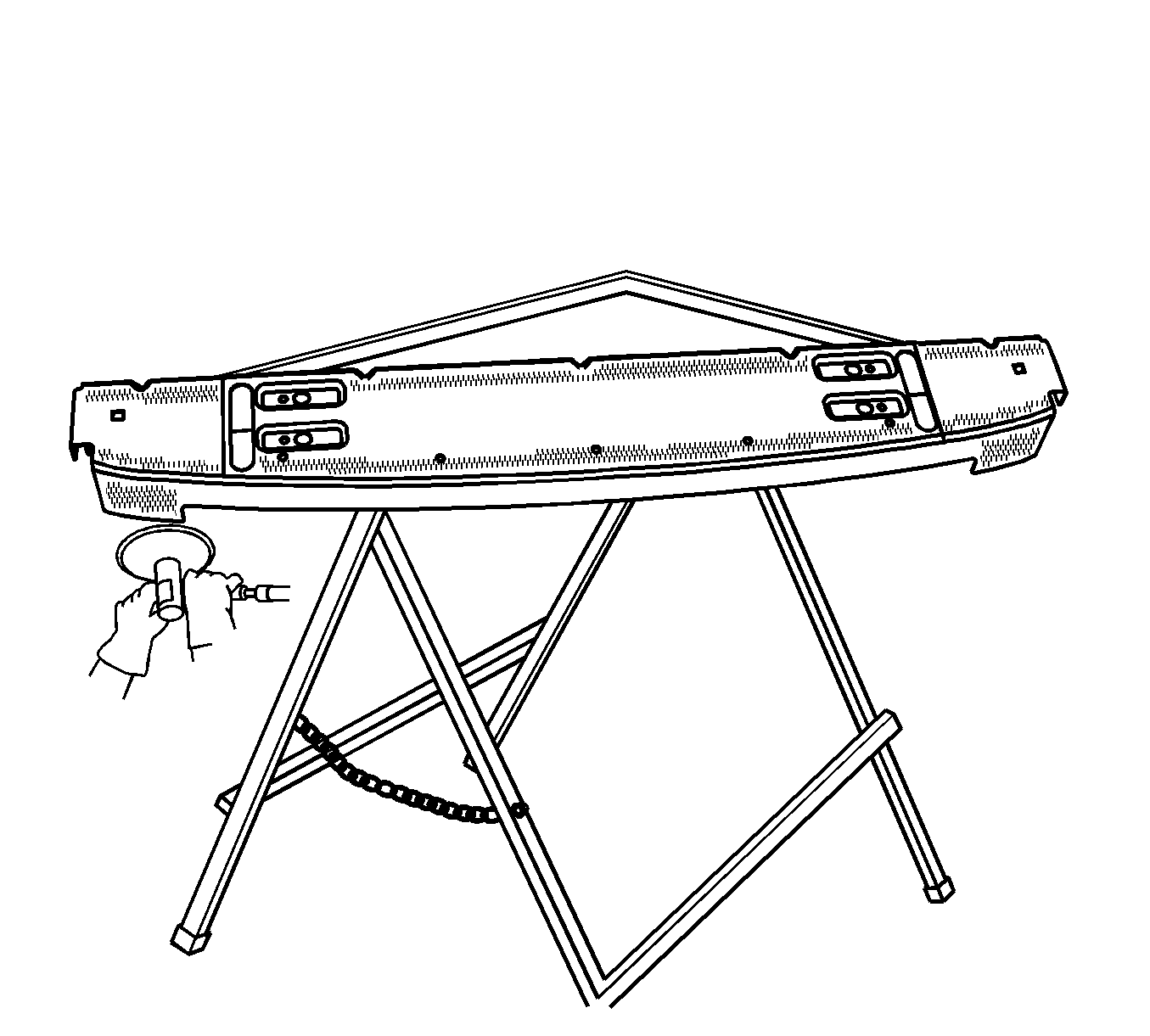
Important: Do NOT drill plug weld holes in the service part.
Notice: Refer to Fastener Notice in the Preface section.
Tighten
Tighten the bolts to 140 N·m (103 lb ft).
