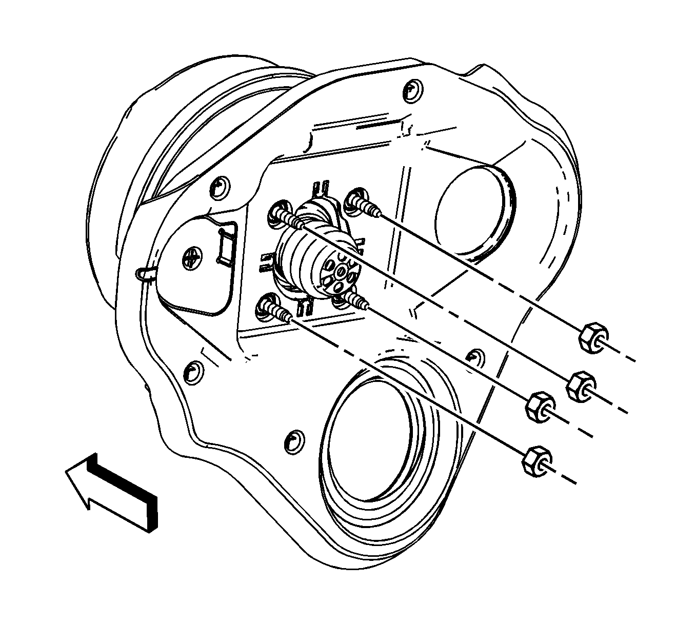
- If replacing the I/P cross car beam, install the HVAC
module from the I/P cross car beam structure. Refer to
HVAC Module Assembly Replacement
.
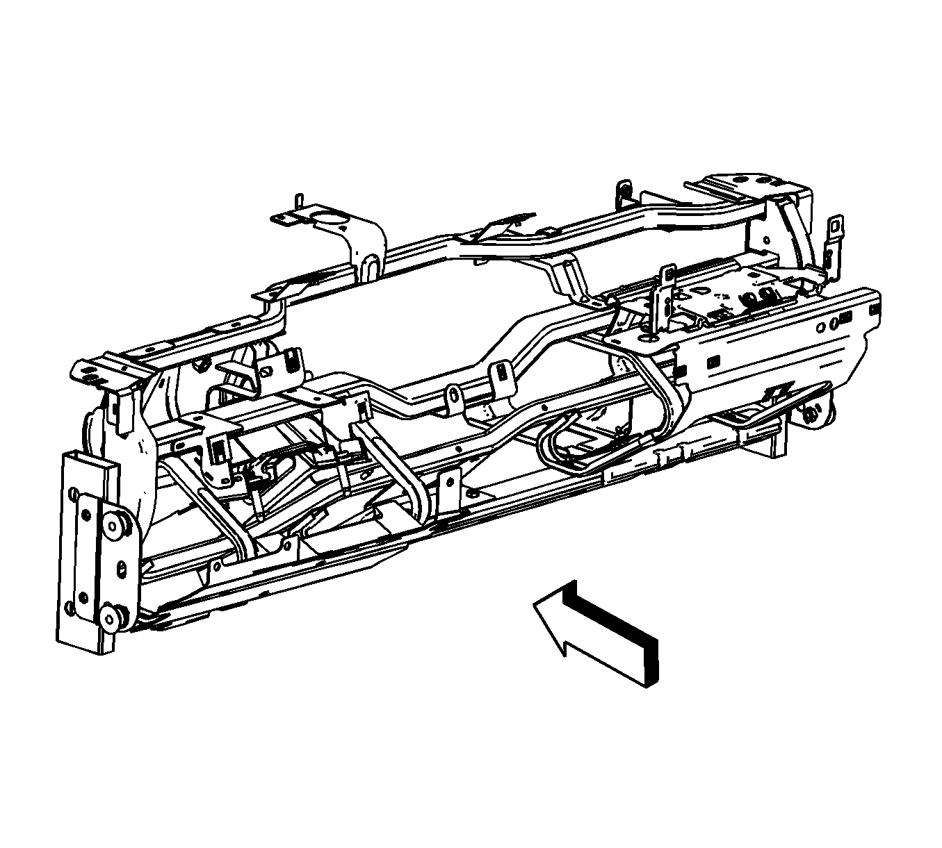
- With the aid of an assistant, carefully install the I/P cross car beam
structure into the vehicle.
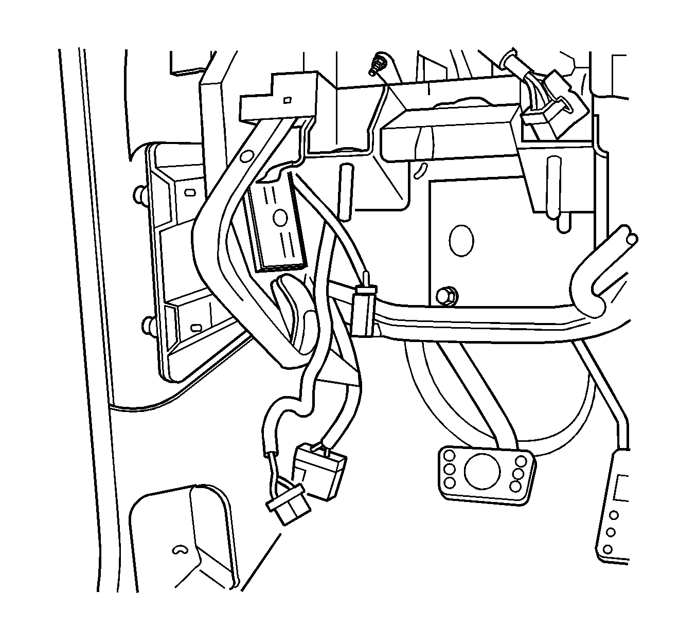
- One at a time, route the following through the I/P
cross car beam structure:
| • | 48-way steering column wiring harness |
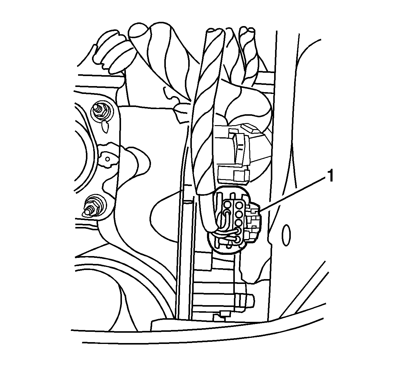
- Connect the electrical connector (1)
to the accelerator switch.
- Install the hazard switch to the cross car beam. Refer to
Hazard and Turn Signal Flasher Replacement
in Lighting
Systems.
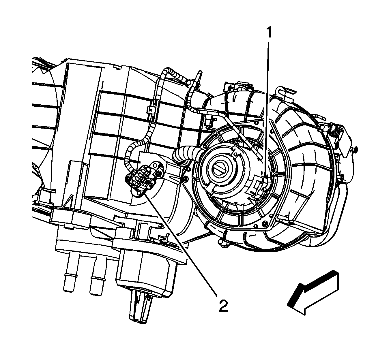
- Connect
the blower motor (1) and resistor (2) electrical connectors.
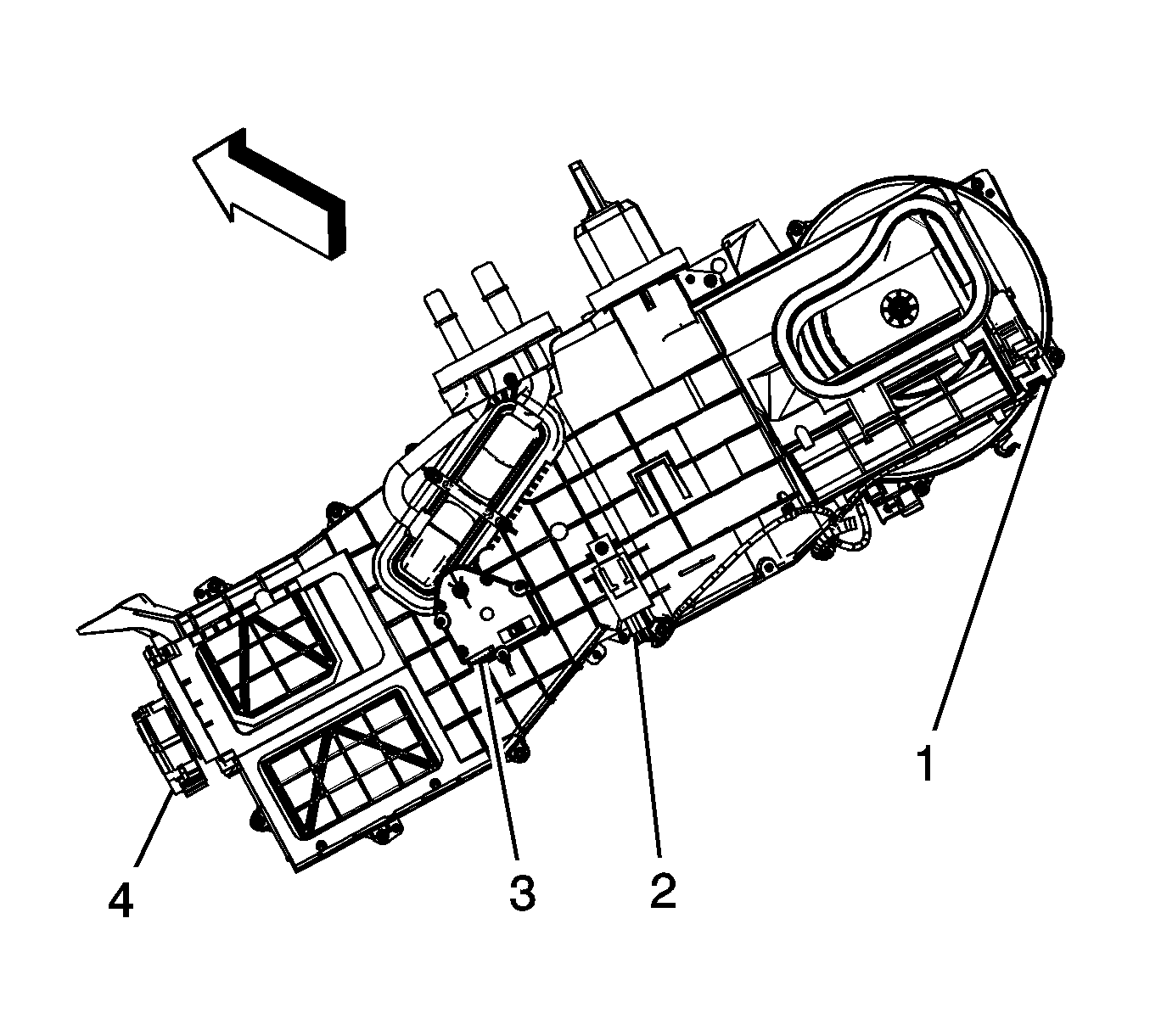
- Connect
the recirculation mode actuator (1) connector.
- Connect the evaporator temperature sensor (2) electrical connector.
- Connect the air temperature door actuator (3) electrical connector.
- Connect the mode actuator (4) electrical connector.
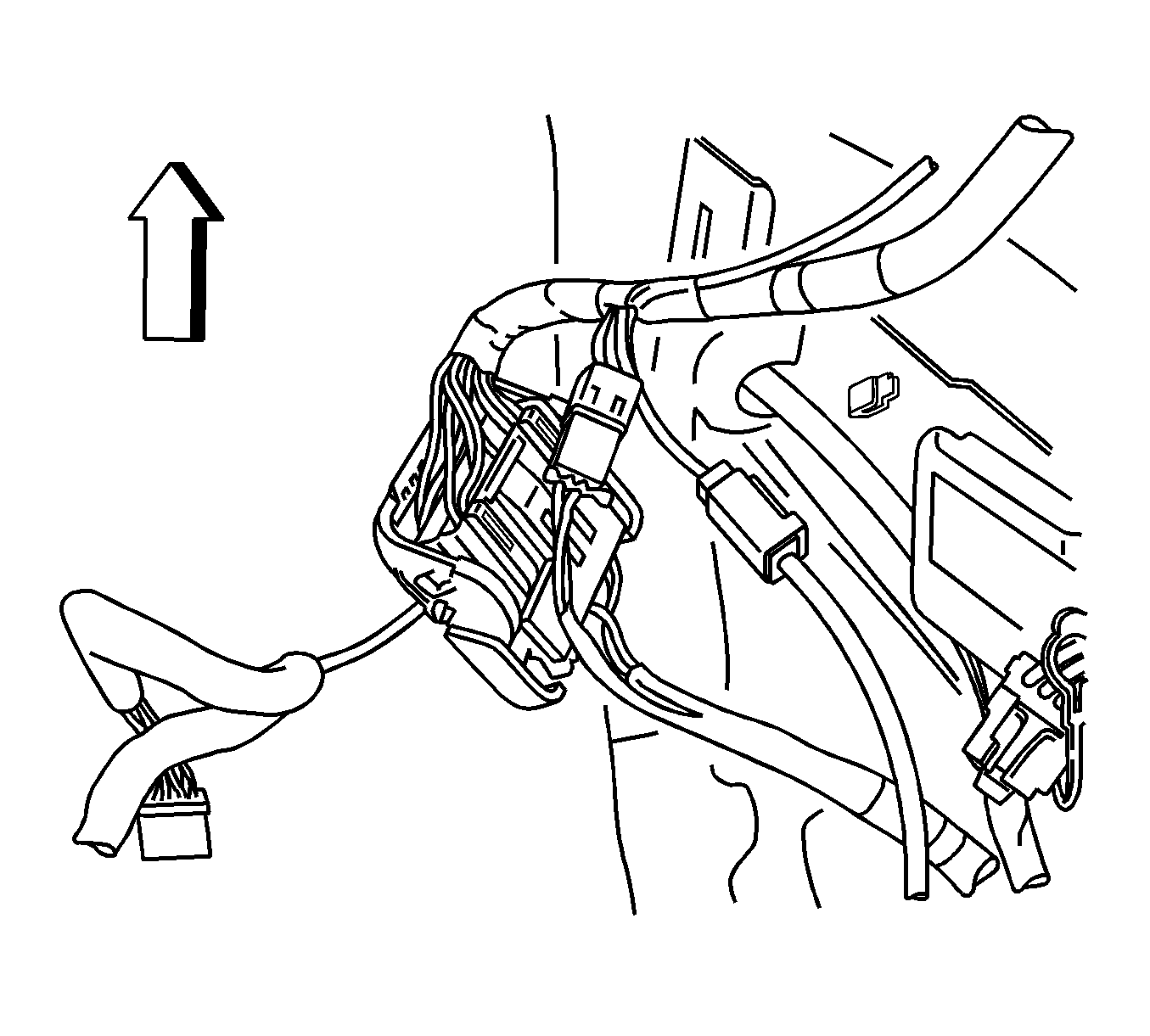
- Connect the in-line connector to the antenna
coaxial cable.
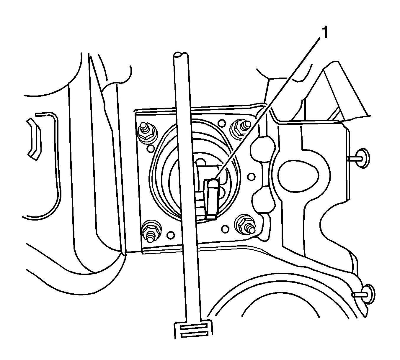
- Install the rod (1) to the brake
pedal arm.
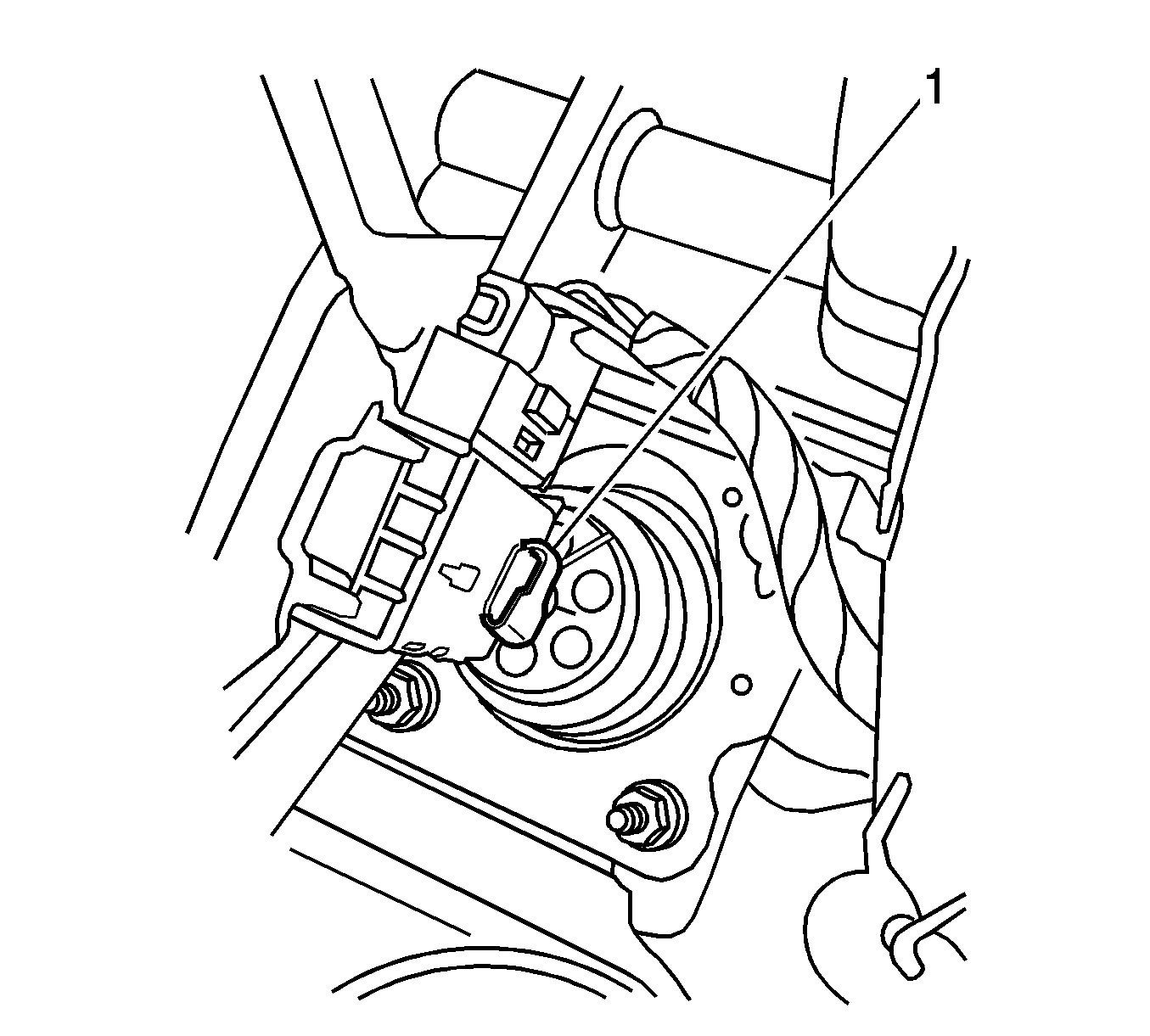
- Install the retainer (1) to the brake booster rod.
- Connect the brake switch electrical connector.
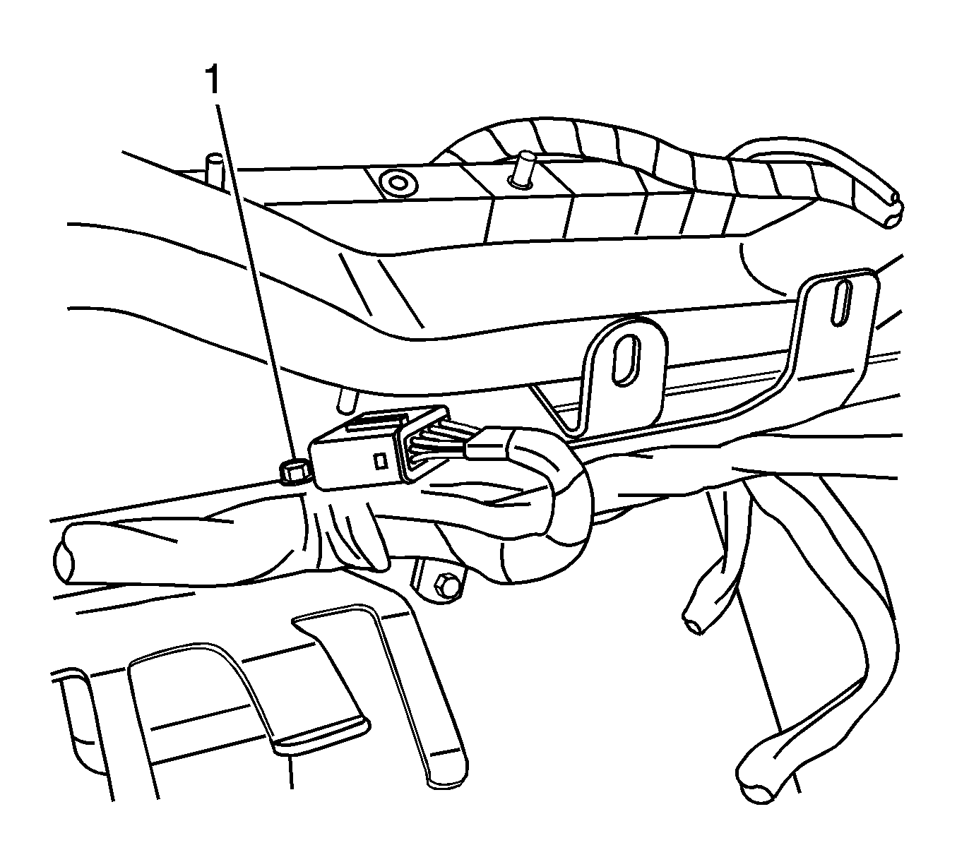
- Install the splice pack to the cross car beam.
Notice: Use the correct fastener in the correct location. Replacement fasteners
must be the correct part number for that application. Fasteners requiring
replacement or fasteners requiring the use of thread locking compound or sealant
are identified in the service procedure. Do not use paints, lubricants, or
corrosion inhibitors on fasteners or fastener joint surfaces unless specified.
These coatings affect fastener torque and joint clamping force and may damage
the fastener. Use the correct tightening sequence and specifications when
installing fasteners in order to avoid damage to parts and systems.
- Install the splice pack fastener (1) to the cross car beam.
Tighten
Tighten the fastener to 2.5 N·m (22 lb in).
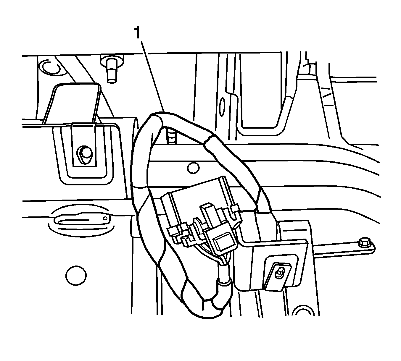
- Located to the right of the steering column,
connect the I/P wiring harness attachment (1) to the I/P cross car beam.
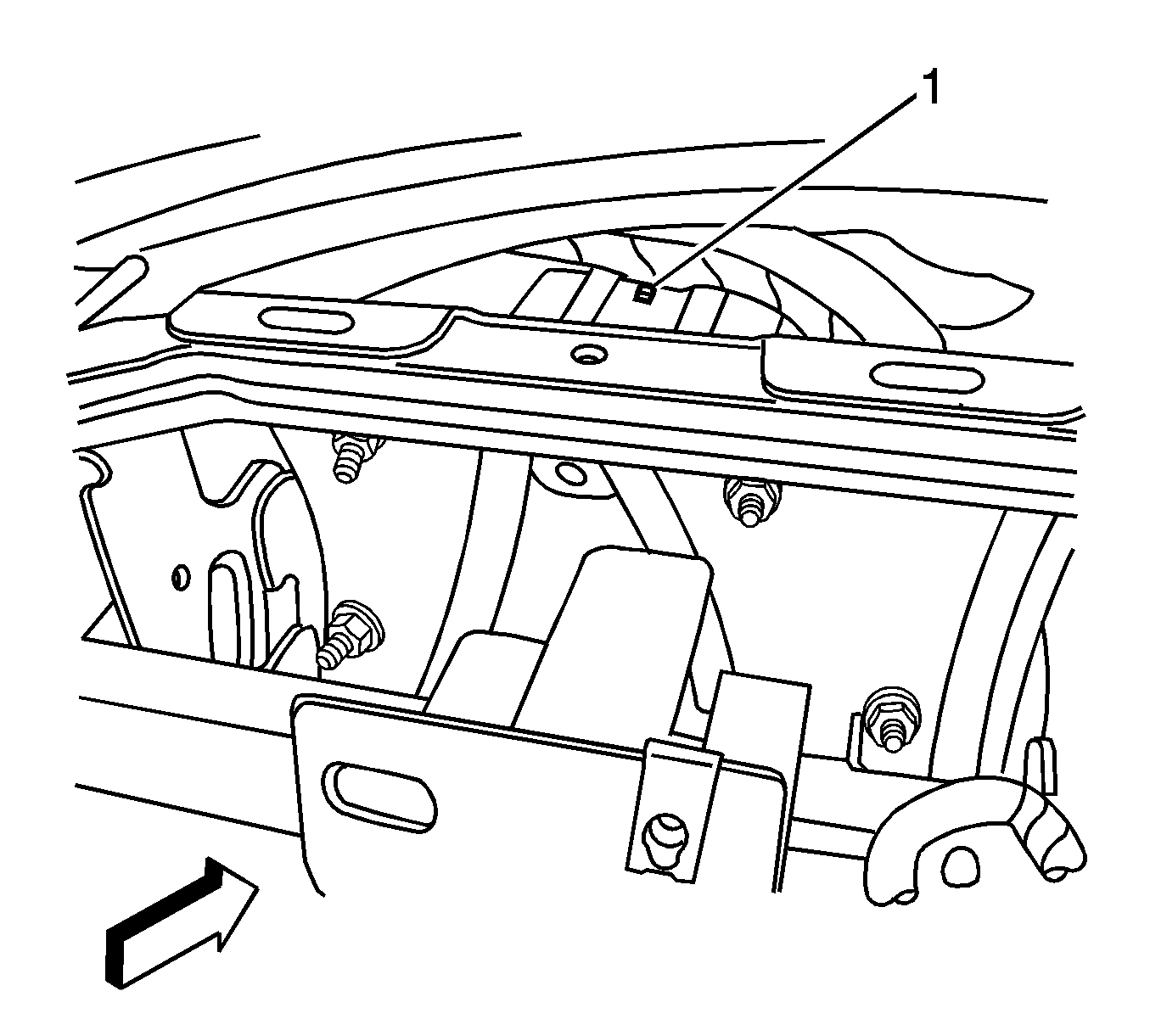
- Located above the steering column, connect
the I/P wiring harness attachment (1) to the I/P cross car beam.
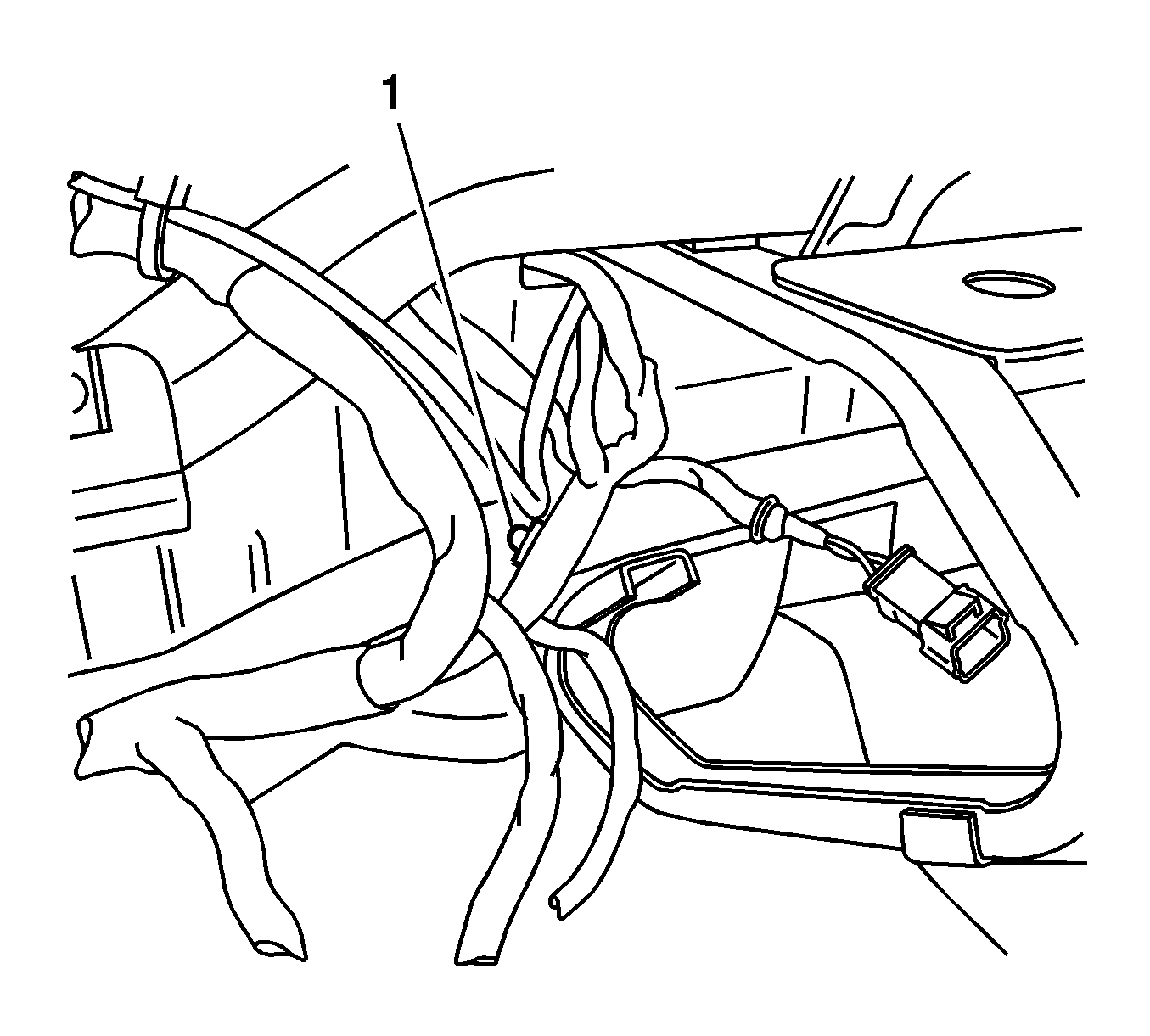
- Located near the radio, connect the I/P
wiring harness attachment (1) to the I/P cross car beam.
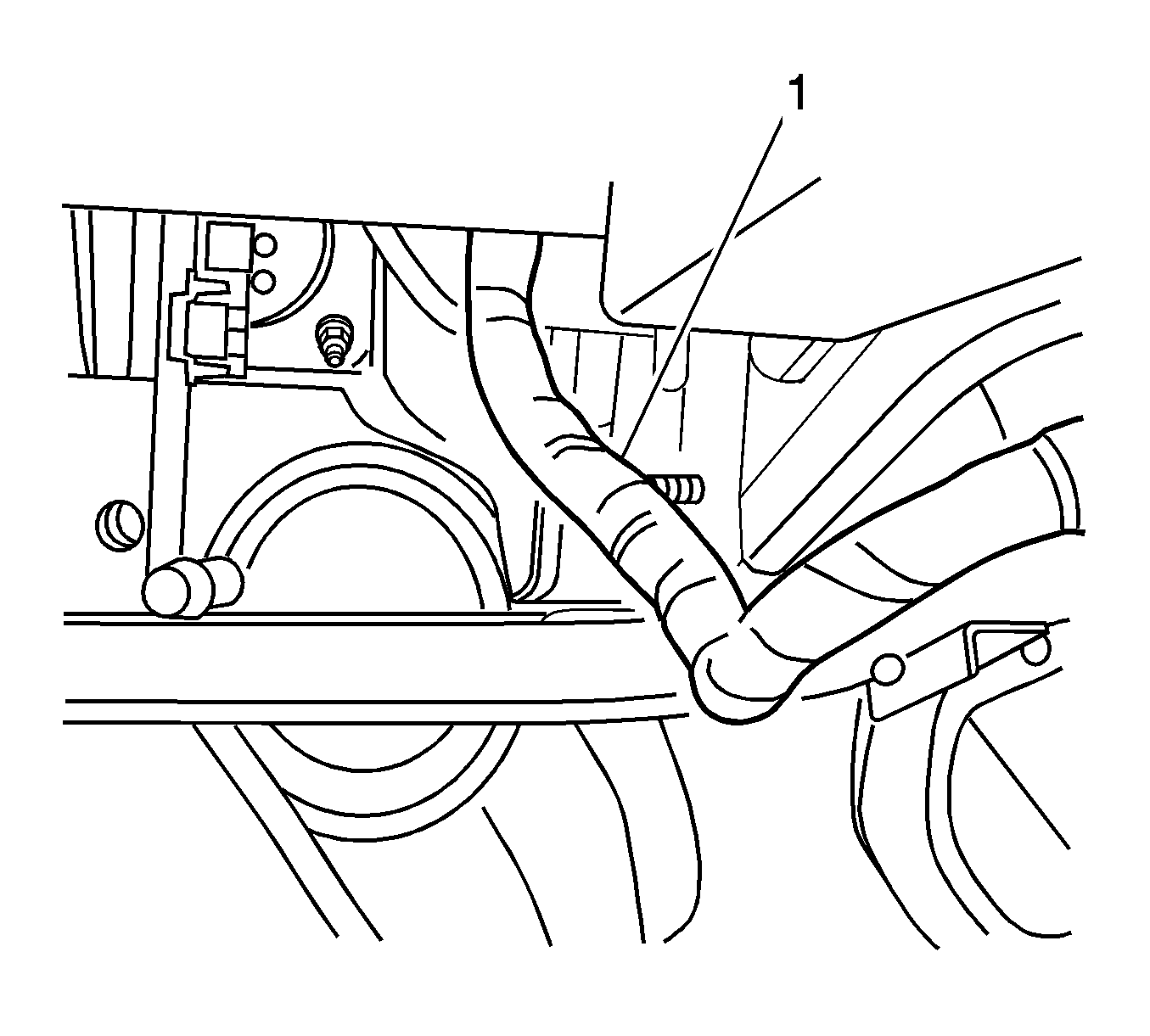
- Located near the HVAC module, connect the
I/P wiring harness attachment (1) to the I/P cross car beam.
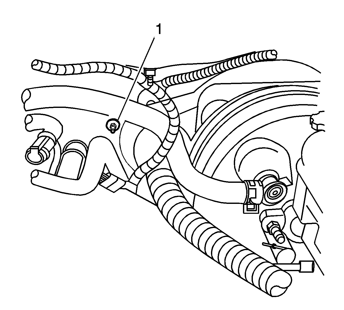
- From the engine compartment, install 1 fastener (1)
to the modular plate inboard from the cowl wiring grommet at the 9 o'clock position.
Tighten
Tighten the fasteners to 36 N·m (27 lb ft).
- Install the 4 fasteners retaining the modular plate to the cross car beam.
Tighten
Tighten the fasteners to 36 N·m (27 lb ft).
Notice: To avoid paint damage, protect the area surrounding the part which you
are removing or installing.
- Apply tape to the door to protect the paint.
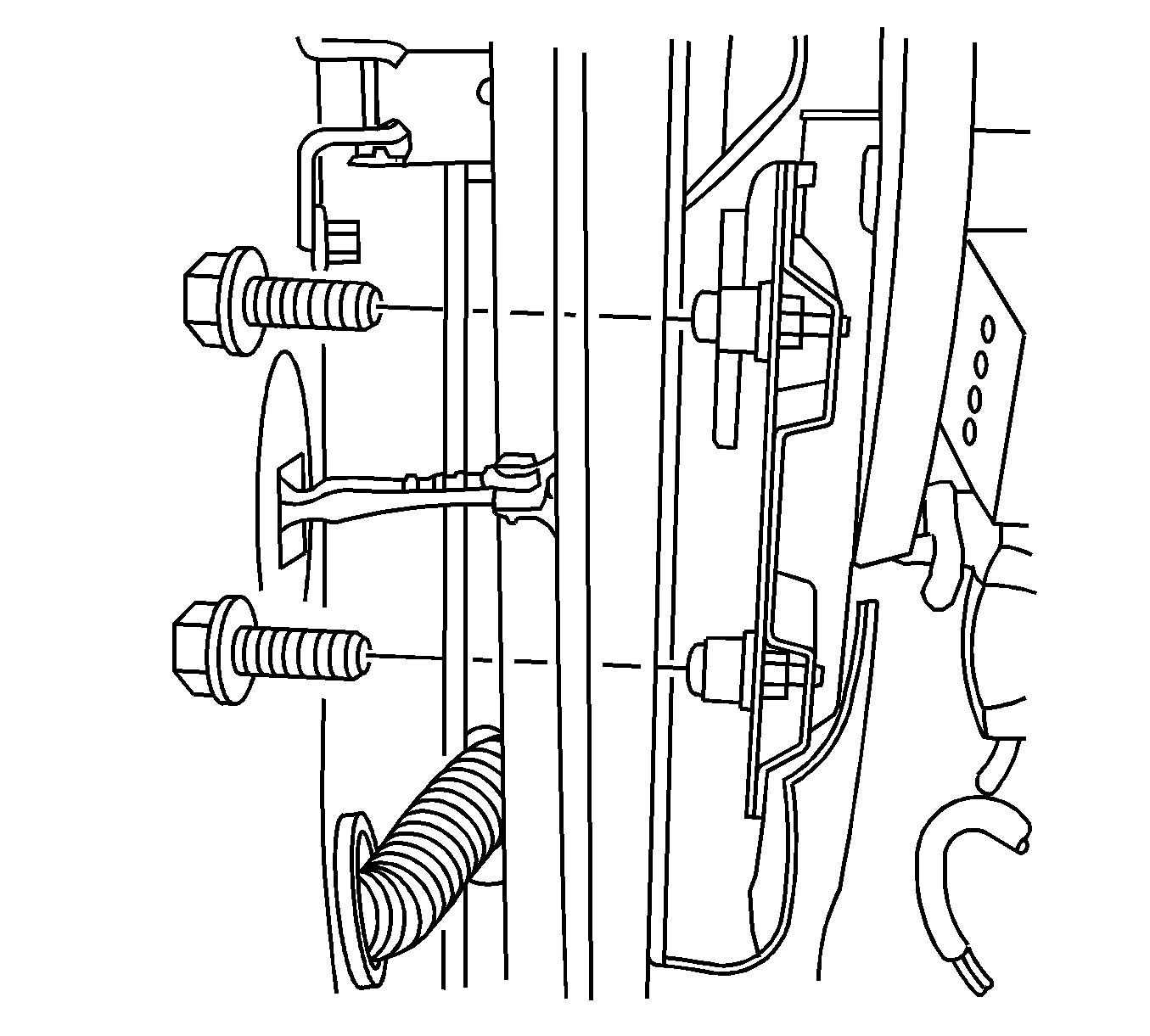
- Install the 4 the left and right hinge pillar
fasteners.
Tighten
Tighten the fasteners to 50 N·m (37 lb ft).
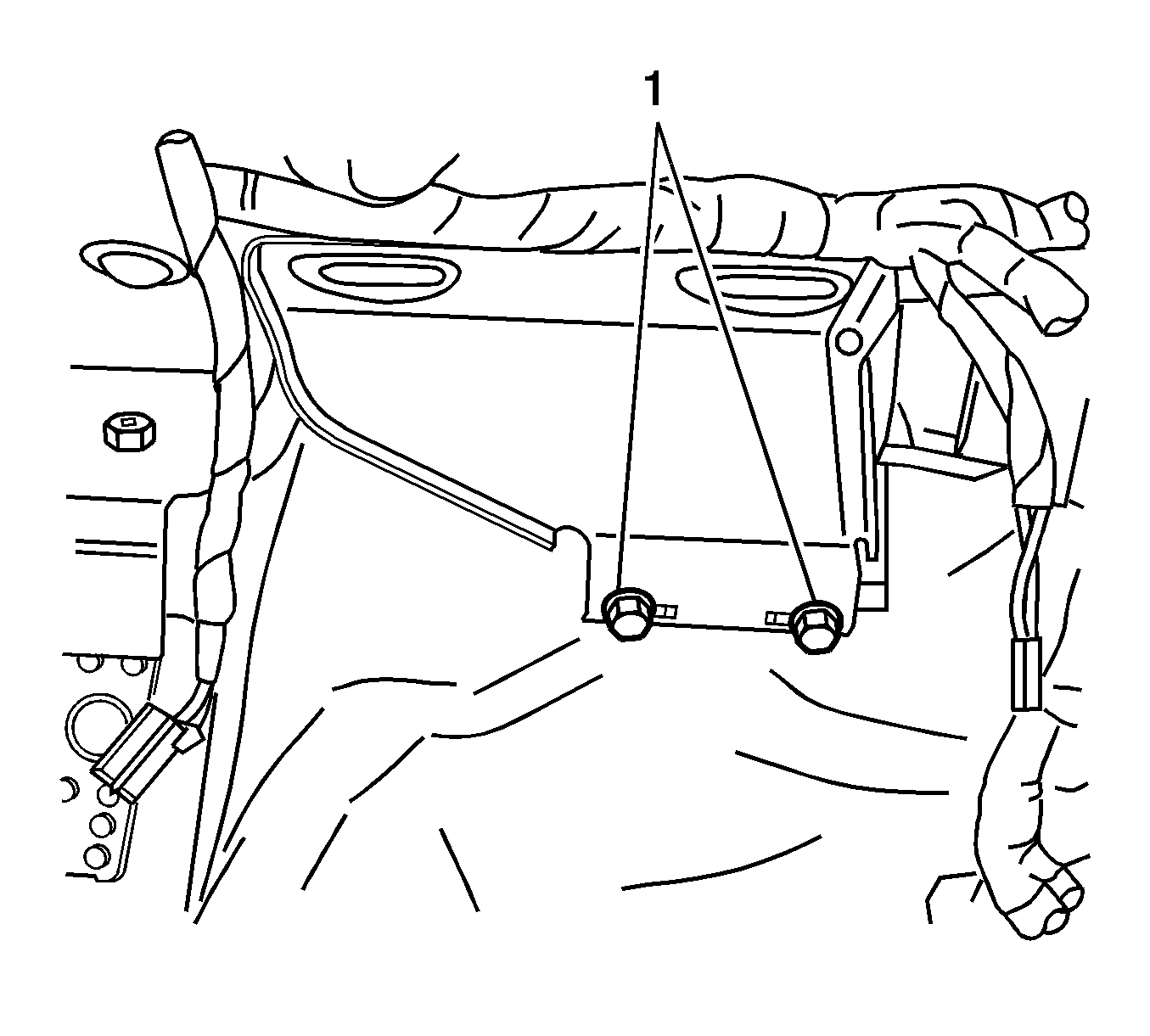
- Install the 2 lower cross car beam fasteners (1)
located in front of the floor console.
Tighten
Tighten the fasteners to 50 N·m (37 lb ft).
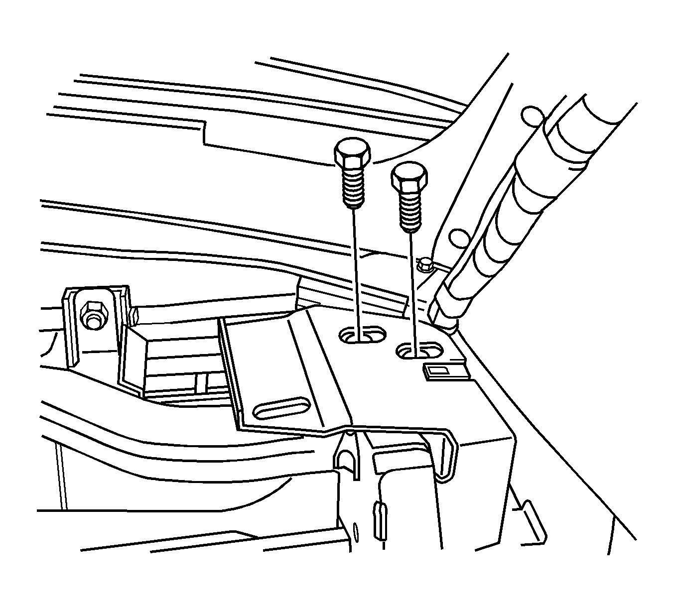
- Install the 2 right top cross car beam fasteners.
Tighten
Tighten the fasteners to 50 N·m (37 lb ft).
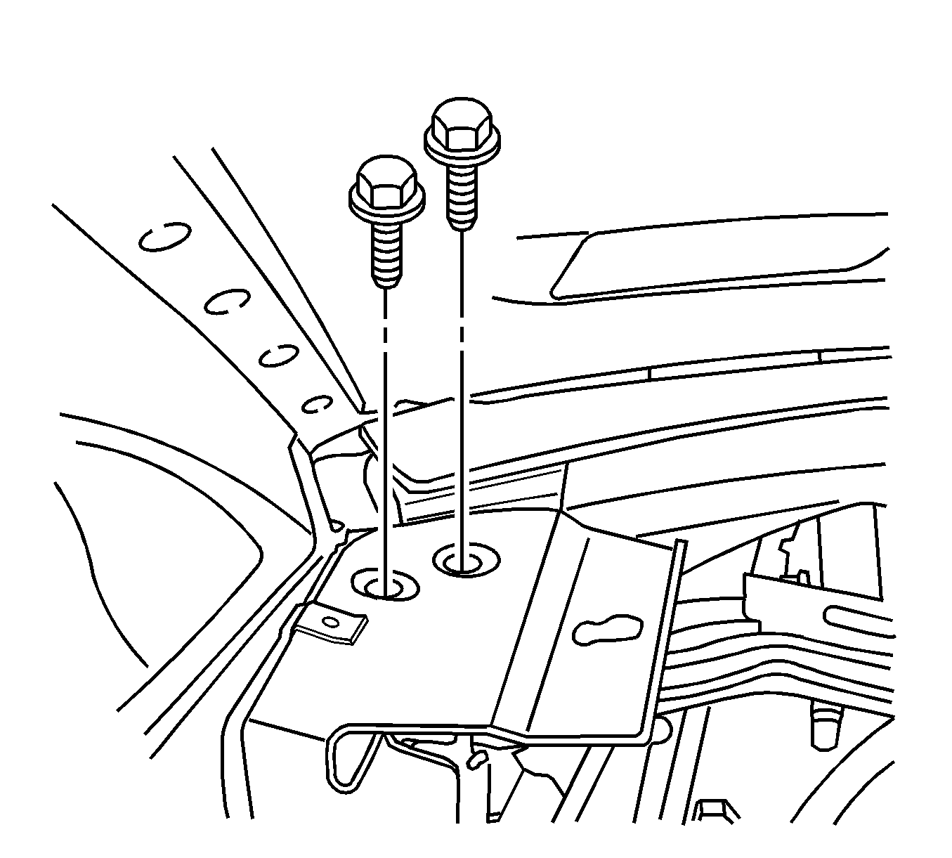
- Install the 2 left top cross car beam fasteners.
Tighten
Tighten the fasteners to 50 N·m (37 lb ft).
- Install the I/P carrier. Refer to
Instrument Panel Carrier Replacement
.
- Install the heater inlet and outlet hoses. Refer to
Heater Inlet Hose Replacement
and
Heater Outlet Hose Replacement
in Heating, Ventilation and Air Conditioning.
- Connect only the compressor hose assembly at the thermal expansion valve.
Refer to
Compressor Hose Assembly Replacement
in Heating, Ventilation and Air Conditioning.
- Install the steering column. Refer to
Steering Column Replacement
in Steering Wheel and Column.
- Connect the negative battery cable. Refer to
Battery Negative Cable Disconnection and Connection
in Engine Electrical.
- Install the left and right seats in the vehicle. Refer to
Seat Replacement
in Seats.


