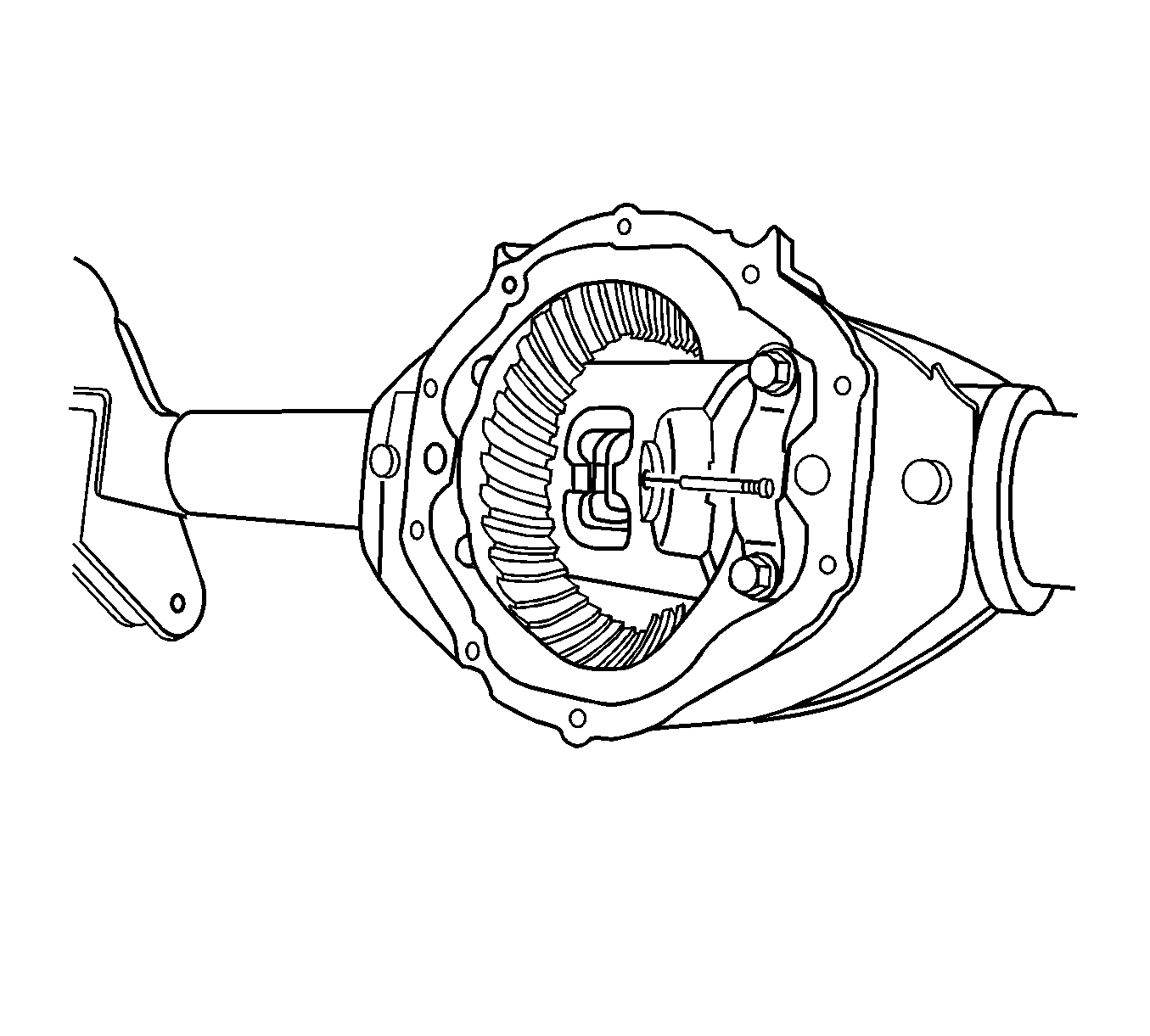
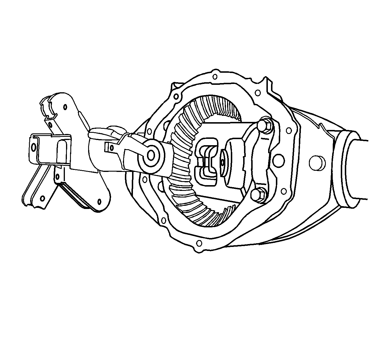
Tools Required
| • | J 34178 Spreader Gage Adapter |
| • | J 45222 Axle Housing Spreader |
| • | J 8001 Dial Indicator Set |
Removal Procedure
Important: Group and mark the shims together as originally removed. If you remove or replace the ring and pinion gearset, perform the bearing preload, backlash, and gear tooth contact pattern check in order to ensure proper contact of the gears. If you reinstall or replace the differential assembly without replacing any other component (i.e. pinion and ring gear set, bearings. etc.) then you may reinstall the assembly with the original shims in their original locations. Always perform a gear tooth contact pattern check, even when you remove only the differential assembly.
- Raise the vehicle. Refer to Lifting and Jacking the Vehicle in General Information.
- Remove the rear axle tie rod. Refer to Rear Axle Tie Rod Replacement in Rear Suspension.
- Remove the axle shafts. Refer to Rear Axle Shaft Replacement .
- Loosen the bearing cap bolts.
- Install the J 45222 onto the axle housing as shown.
- Install the J 8001-1 (2), the J 8001-2 (3), the J 34178 (4, 6), and the J 8001-3 (5) as shown.
- Preload the J 8001-3 (5) approximately 3/4 of a turn clockwise.
- Rotate the indicator housing to align the indicator needle of the J 8001-3 (5) and the dial indicator face to ZERO.
- Spread the axle housing by turning the clevis screw of the J 34178 while observing the J 8001-3.
- Remove the bearing caps bolts and the caps. Mark the bearing caps left and right.
- Remove the differential assembly from the axle housing.
- Remove the bearing cups, the shims, and the spacers as necessary.
- Remove the J 8001-1, the J 8001-2, the J 34178 , and the J 8001-3.
- Remove the J 45222 .
- Remove the differential side bearings, if necessary. Refer to Differential Side Bearings Replacement .
- Remove the ring gear, if necessary. Refer to Drive Pinion and Ring Gear Replacement .
Important: If the differential assembly is to be re-installed, install the thrust block and the thrust block lock bolt after removing the axle shafts in order to retain the alignment of the differential gears.
Do not remove the bearing cap bolts at this time.
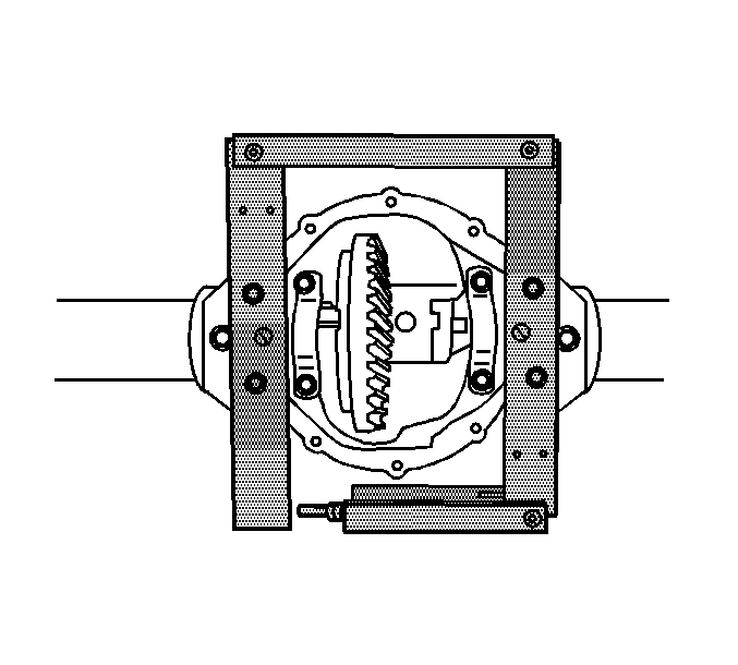
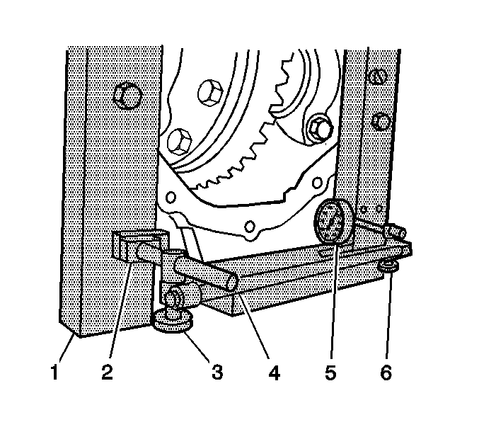
Spread the housing just enough to remove the differential assembly. Do not spread the housing more than 1.02 mm (0.040 in).
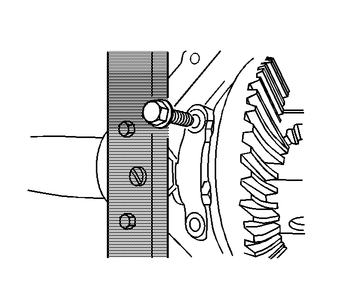
Caution: To prevent personal injury and/or component damage, support the differential case when removing the case from the axle housing. If the case is not supported, the differential case could fall and cause personal injury or damage to the differential case.
Notice: When removing the differential case from the axle housing, do not damage the cover gasket surface. If the cover gasket surface is damaged, lubricant may leak from the axle and cause premature failure of the axle assembly.
Mark the cups and shims left and right and in the proper order as necessary. Place the cups and the shims with the bearing caps.
Installation Procedure
- Install the ring gear, if necessary. Refer to Drive Pinion and Ring Gear Replacement .
- Install the differential side bearings, if necessary. Refer to Differential Side Bearings Replacement .
- Lubricate the differential side bearings with axle lubricant. Use the proper fluid. Refer to Fluid and Lubricant Recommendations in Maintenance and Lubrication.
- Install the J 45222 onto the axle housing as shown.
- Install the J 8001-1 (2), the J 8001-2 (3), the J 34178 (4, 6), and the J 8001-3 (5) as shown.
- Preload the J 8001-3 (5) approximately 3/4 of a turn clockwise.
- Rotate the indicator housing to align the indicator needle of the J 8001-3 (5) and the dial indicator face to ZERO.
- Spread the axle housing by turning the clevis screw of the J 34178 while observing the J 8001-3.
- Place the differential assembly, with the bearing cups installed, into the axle housing.
- Install the bearing caps and the bolts.
- Adjust the differential side bearing preload. Refer to Differential Carrier Bearing Preload Adjustment .
- Adjust the backlash. Refer to Backlash Adjustment .
- Perform a gear tooth contact pattern check. Refer to Gear Tooth Contact Pattern Inspection .
- Tighten the bearing cap bolts.
- Remove the thrust block lock bolt.
- Remove the thrust block.
- Install the axle shafts. Refer to Rear Axle Shaft Replacement .
- Install the rear axle tie rod. Refer to Rear Axle Tie Rod Replacement in Rear Suspension.
- Lower the vehicle.


Spread the housing just enough to install the differential assembly. Do not spread the housing more than 1.02 mm (0.040 in).
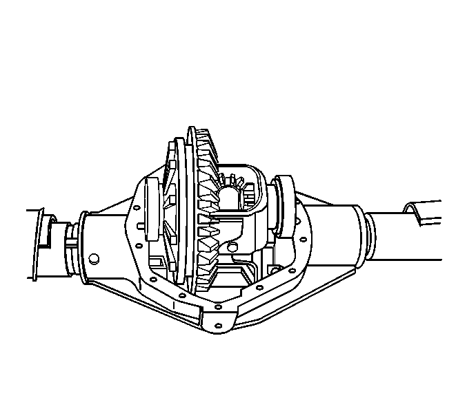
Support the differential assembly in order to keep the assembly from falling out of the axle housing.

Do not torque the bearing cap bolts at this time.
Notice: Refer to Fastener Notice in the Preface section.
Tighten
Tighten the bearing cap bolts to 75 N·m (55 lb ft).
