Caution: Refer to Eye Protection Caution in the Preface section.
Caution: Refer to Folding Top Hydraulic Pressure Caution in the Preface section.
Caution: Refer to Servicing Electrical Components Caution in the Preface section.
Notice: Refer to Cylinder Hoses Notice in the Preface section.
- Place the folding top in the open position.
- Open the stowage compartment lid.
- Disconnect the battery. Refer to
Battery Negative Cable Disconnection and Connection
in Engine Electrical.
- Place a protective cover over the rear compartment interior and the adjacent body panels.
- Remove the body accessory compartment. Refer to
Body Rear Accessory Compartment Replacement
.
- Remove the hydraulic pump noise covers.
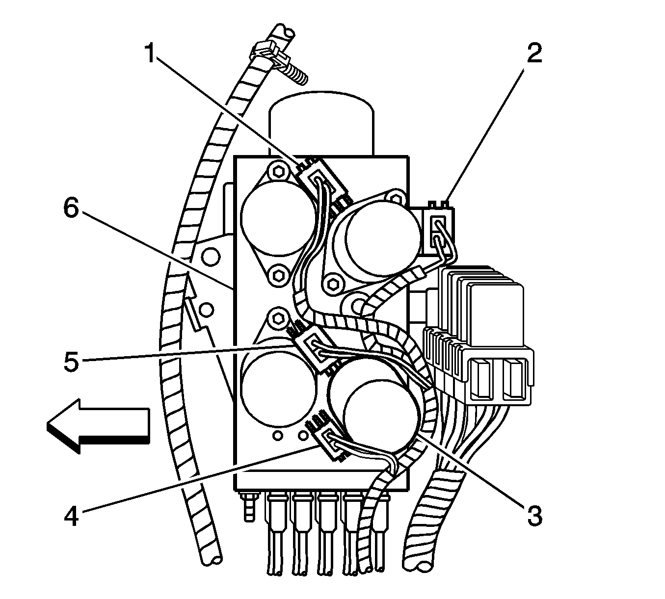
- Remove the 4 electrical connectors from the hydraulic pump solenoids as follows:
| • | Connector C 4 Green, to solenoid valve 4 (with Red and Green CKT) |
| • | Connector C 3 Orange, to solenoid 3 (with a LT Blue CKT) |
| • | Connector C 1 Green to solenoid valve 1 (with WHITE CKT) |
| • | Connector C 2 Blue to solenoid valve 2 (with Dark BLUE CKT) |
| • | Folding Top Pump with Motor (6) |
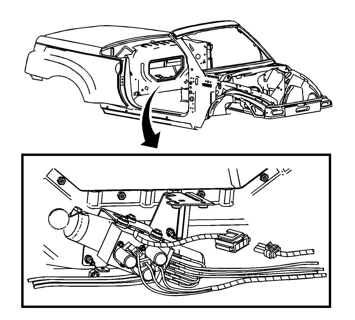
- Disconnect the 2 electrical connectors from the hydraulic pump.
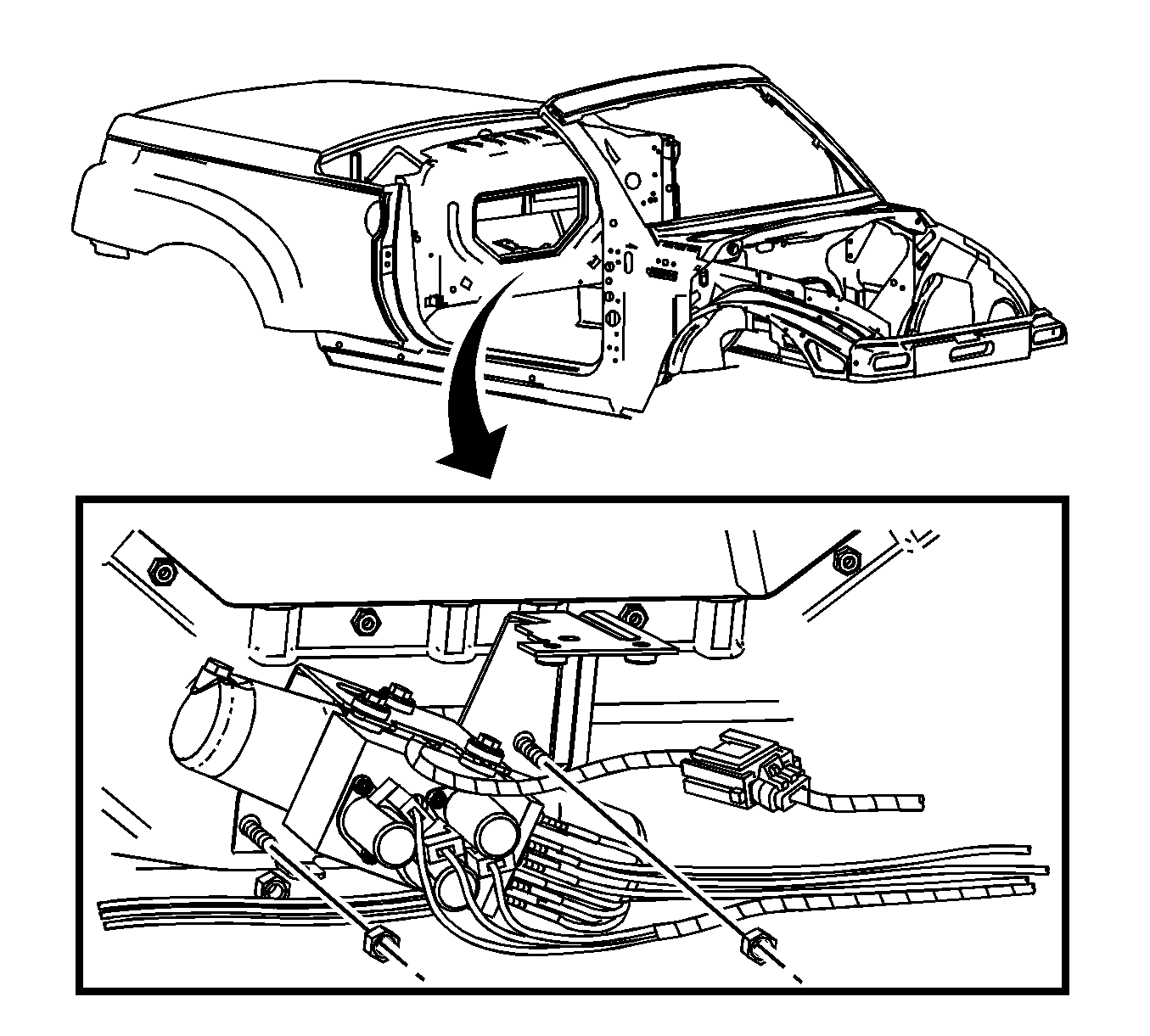
- Remove the nuts from the hydraulic pump bracket.
- Lift the pump up and out of the storage compartment and set the pump on the protective covering.
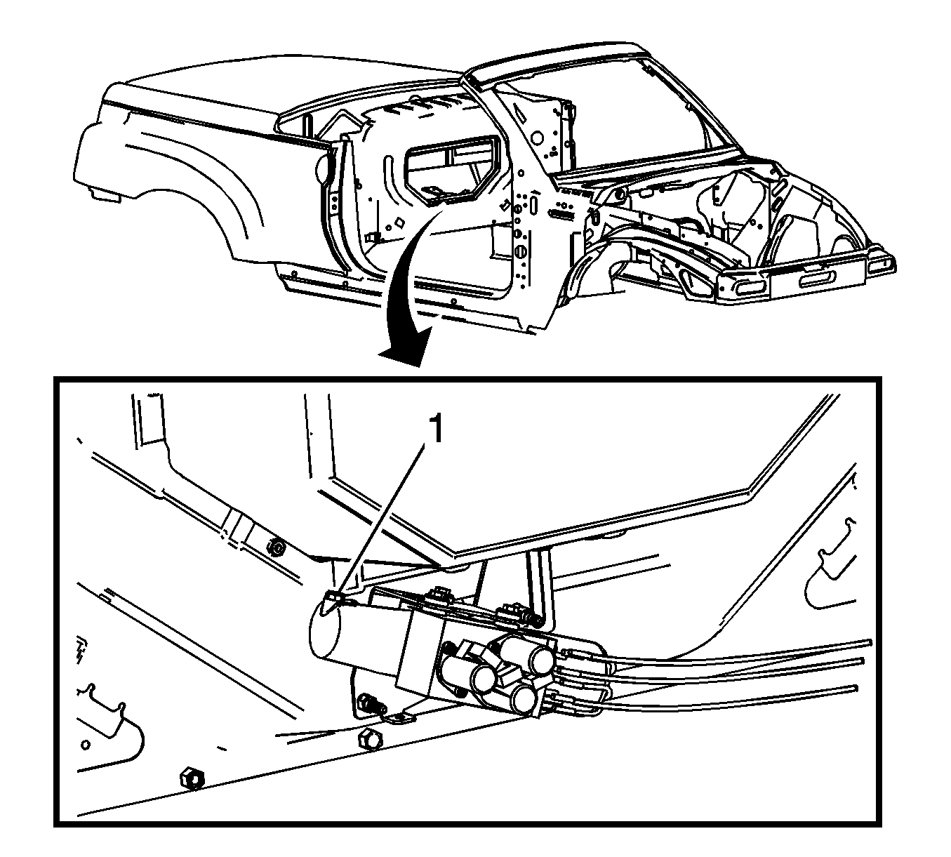
- Remove the reservoir filler plug.
Important: If you are replacing hoses from more than one cylinder, complete the procedure for one cylinder before you begin with another.
- Remove the hydraulic cylinder (1) from the mounting location. DO NOT remove the hoses from the cylinder at this time. Refer to
Folding Top Hydraulic Cylinder Replacement
.
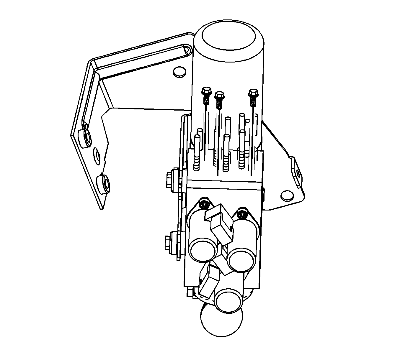
- Remove the bolts from the pump manifold plate.
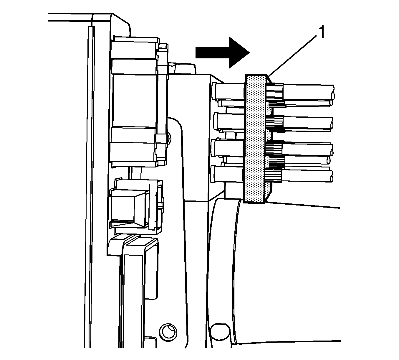
- Carefully lift up on the manifold plate (1).
Important: Each cylinder is serviced by 2 hoses. In order to simplify the routing of the new hose, replace both hoses as a unit. Corresponding hose numbers are also stamped on the manifold plate to aid in identification.
- Locate the pair of cylinder hoses that need replacement.
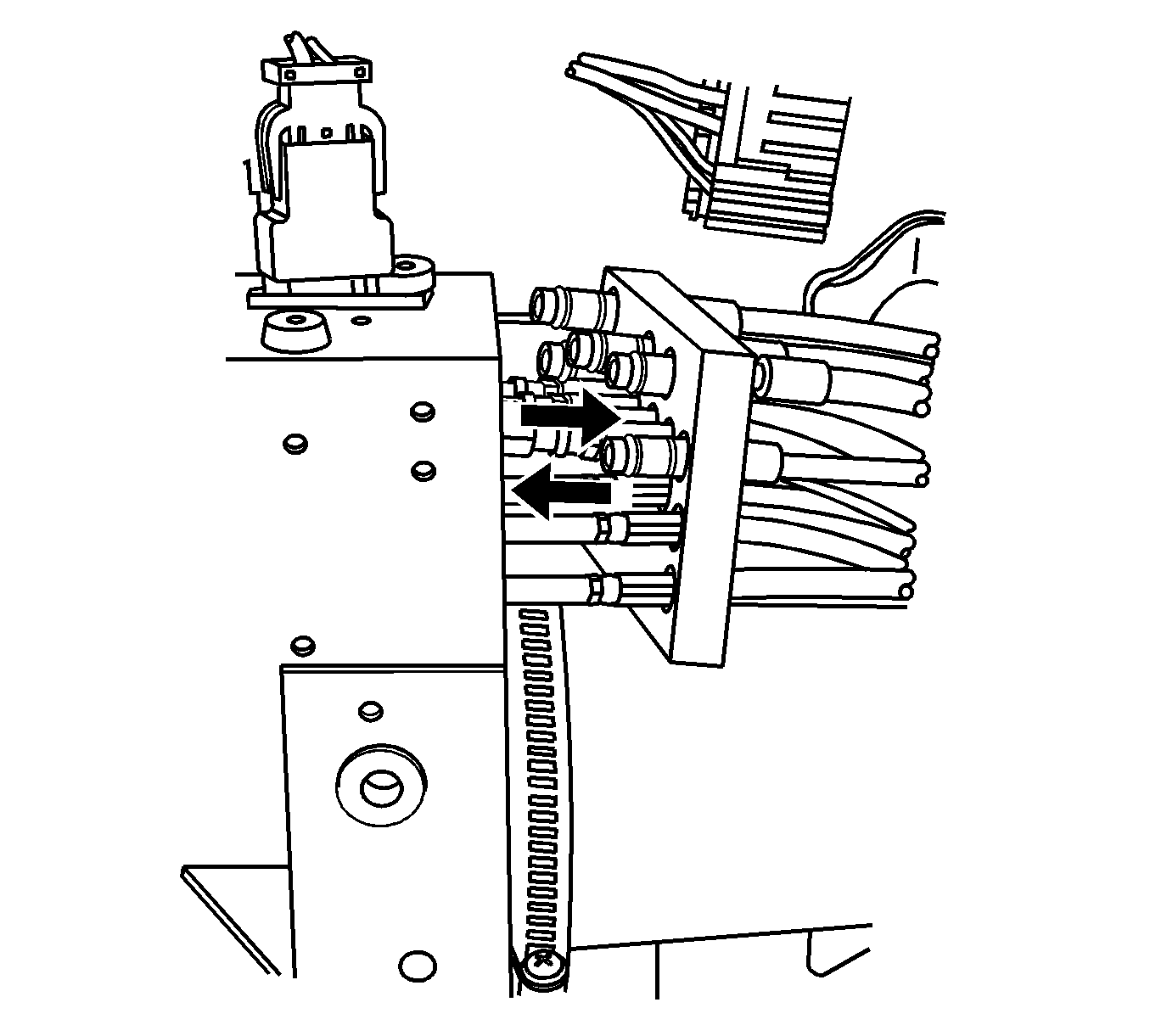
Important: Remove the 2 hose connections one at a time. Repeat this entire procedure for the second hose.
- For each pair of hoses being replaced, remove one hose by pulling straight up from the pump. Use a clean shop towel to control any hydraulic fluid leakage.
- Push the hose back through the manifold plate.
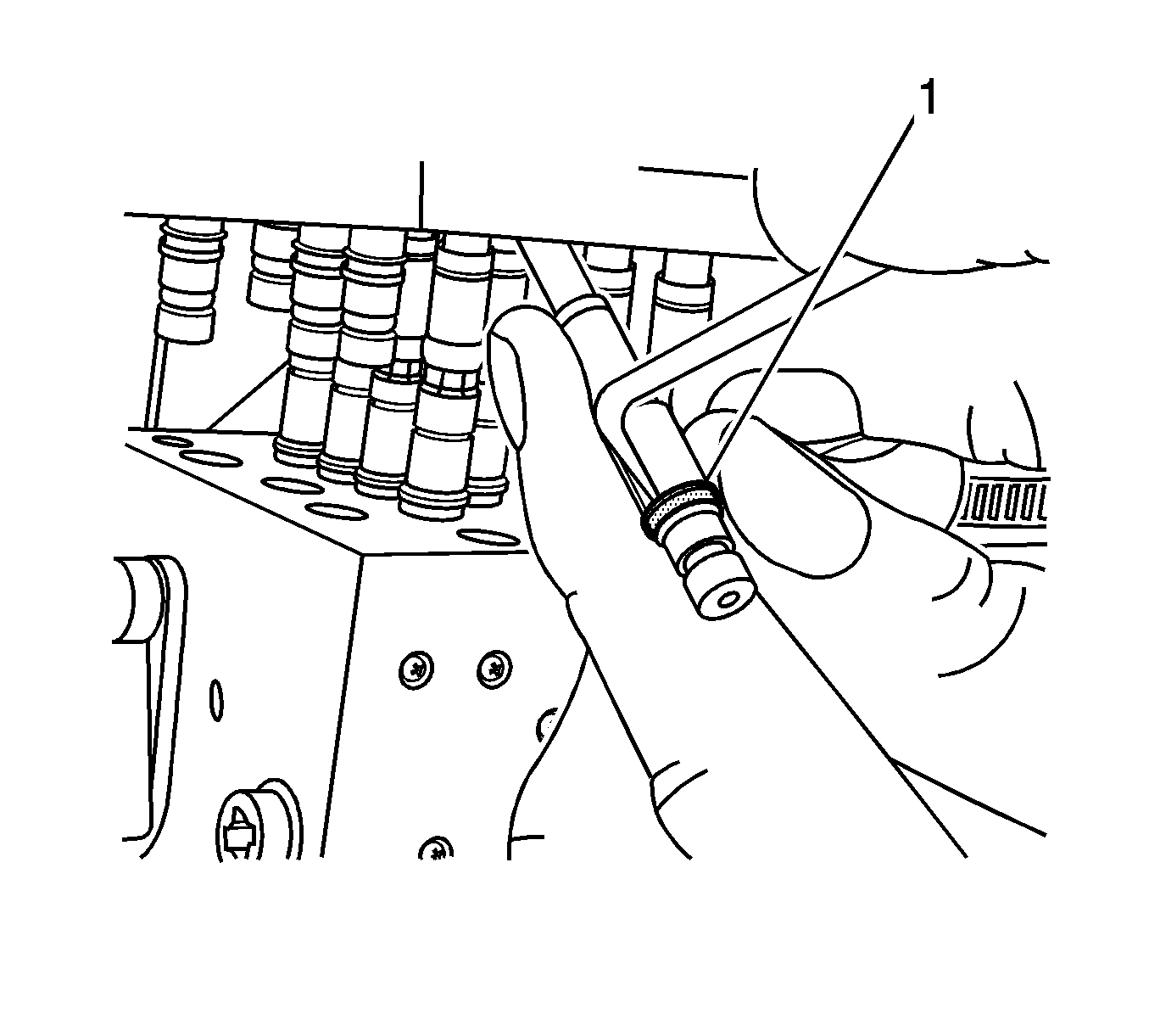
- Remove the hose retaining ring (1).
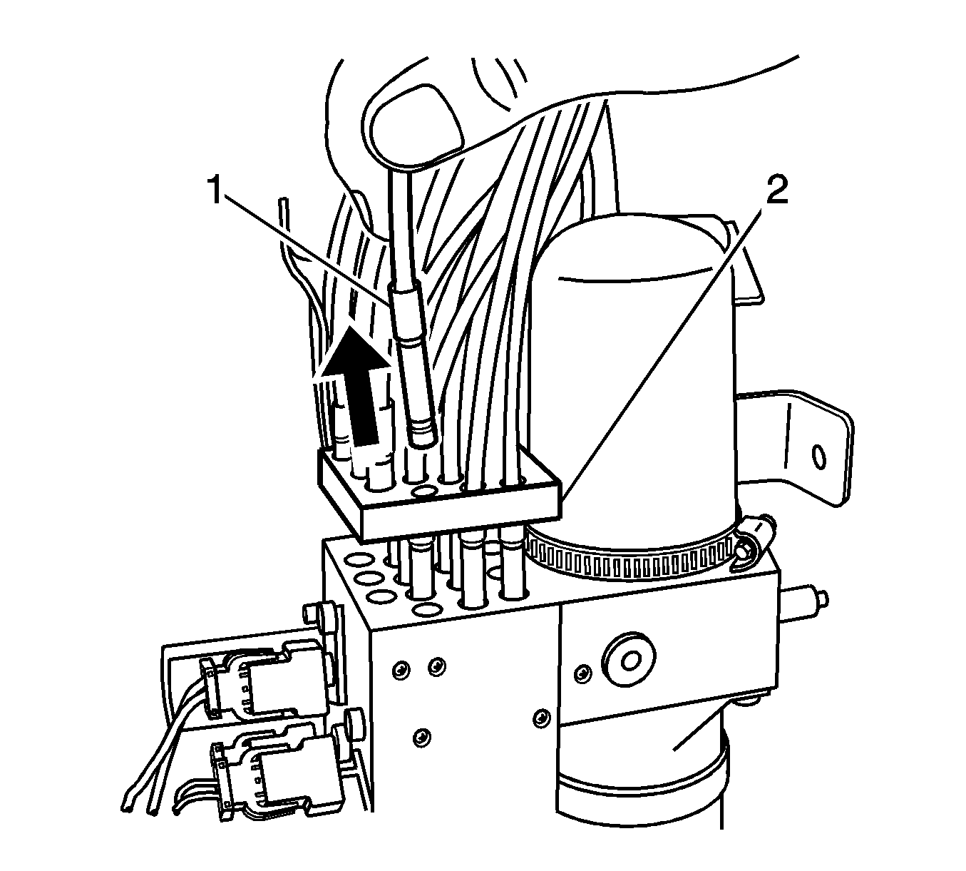
- Remove the hose (1) from the manifold plate (2).
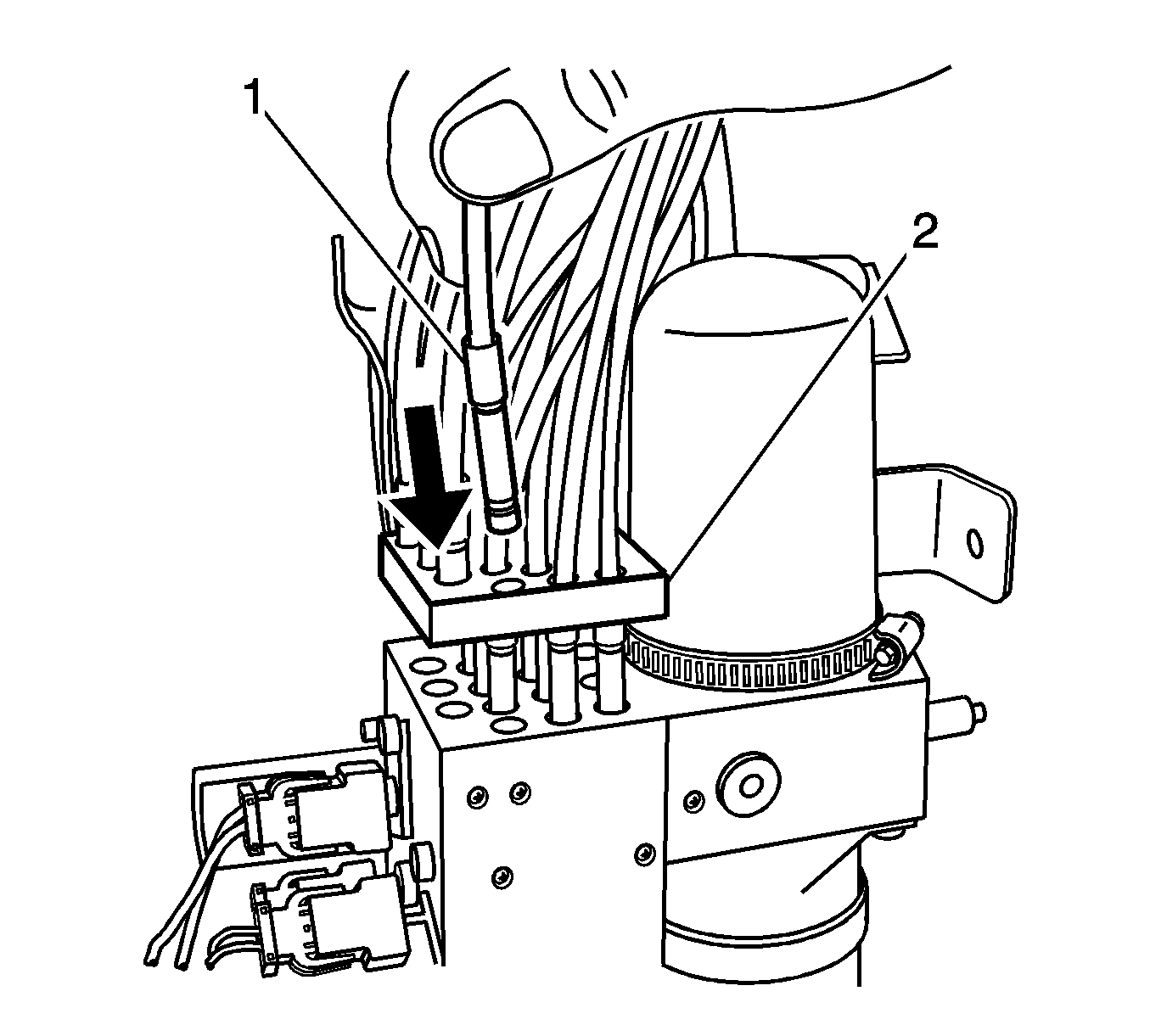
- Push the manifold end of the new hose (1) through the manifold plate (2).
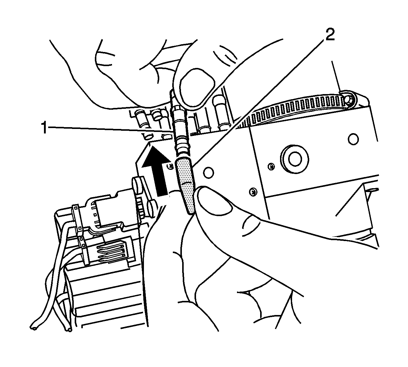
- Using the
BO-47666
, install a new hose-retaining ring (1) onto the
hoses.
- Push the assembly cone (2) over the end of the hose until the cone is fully seated.
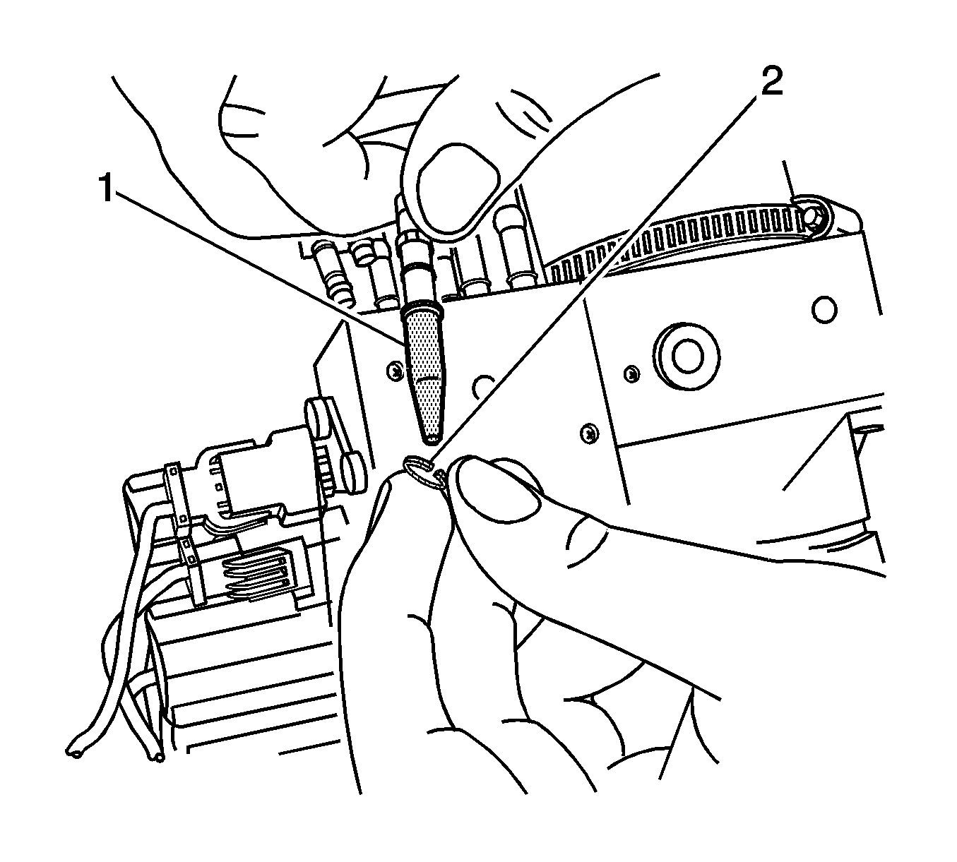
- Install the retaining ring (2) onto the assembly cone (1).
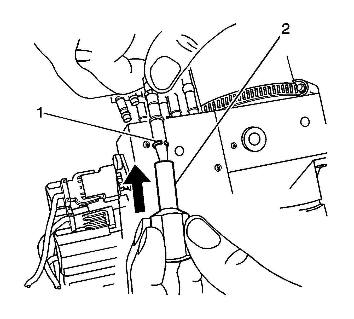
- Using the
BO-47666
, push the retaining ring into place (2) onto the
hose.
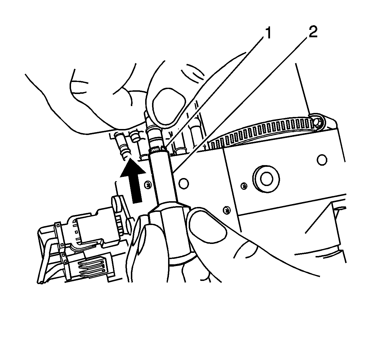
- Push the hose into the manifold plate until the hose is fully seated (1).
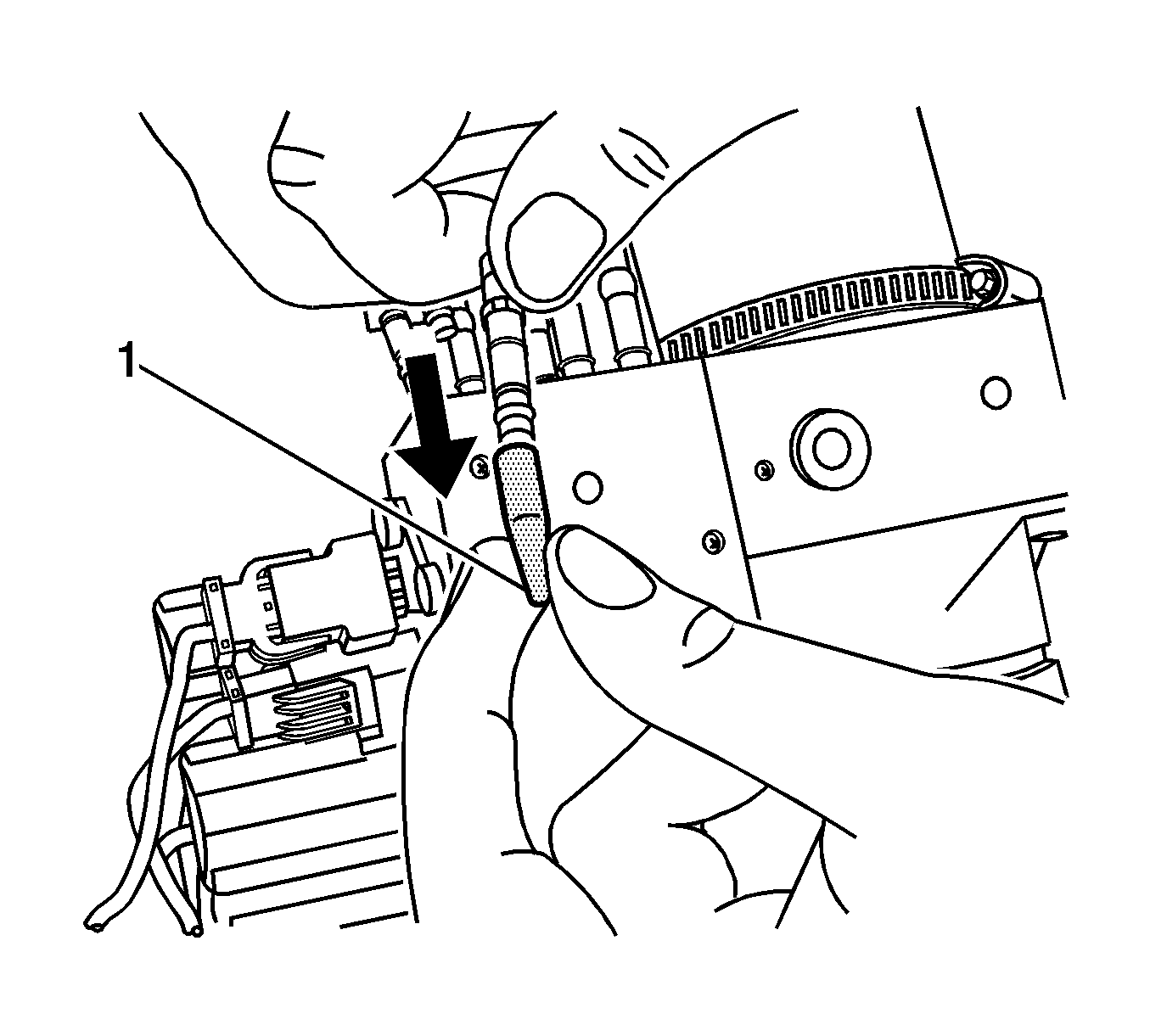
- Remove the assembly cone (1).
- Repeat this procedure for the other hose in the pair.
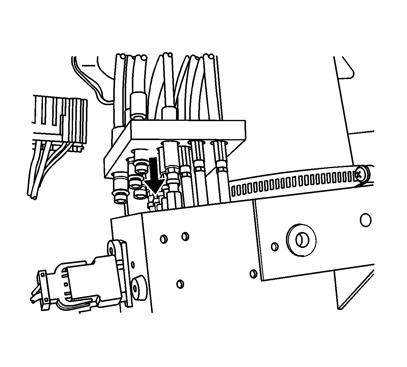
- Align the manifold plate bolt holes to the holes on the pump. This will ensure that the cylinder hoses are placed in the correct port.
- Align the cylinder hoses into each port and push down until the hoses are seated properly in the hydraulic pump manifold.

- Install the manifold plate bolts. DO NOT tighten.
Notice: Refer to Fastener Notice in the Preface section.
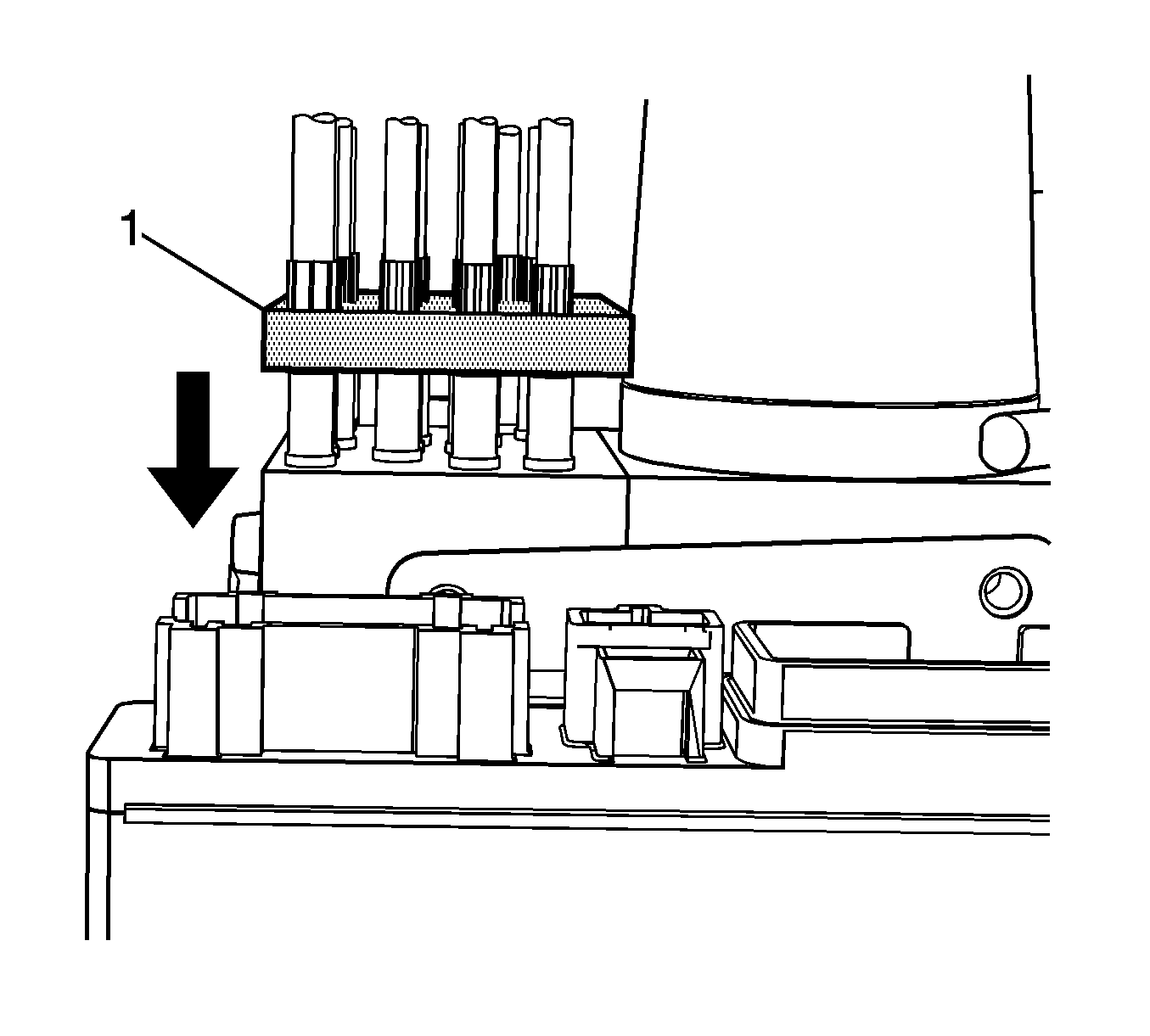
- Push down on the manifold plate (1) and verify that all of the cylinder hoses are seated properly.
Tighten
Tighten the bolts to 10 N·m (88 lb in).
Important: Improper hose routing can lead to hose failure as a result of rubbing or pinching.
- Route the new hose set in the exact same way as the set being replaced.
Important: Remove only one fastener at a time so that the amount of slack between fasteners can be exactly duplicated between the hose sets.
- Depending on the hose set, you may have to remove and replace the following components:
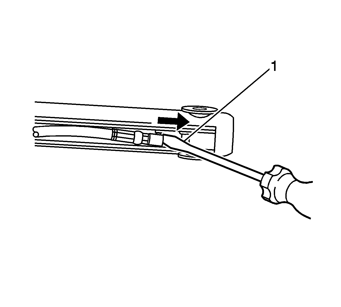
Important: Remove the 2 hose connections one at a time. Repeat this entire procedure for the second hose.
- Use a small flat-bladed tool (1) to release the retainer clip from one of the cylinder hoses.
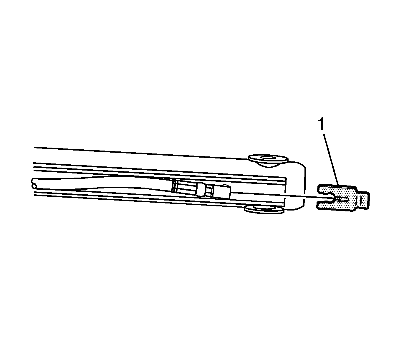
- Remove the retainer clip (1).
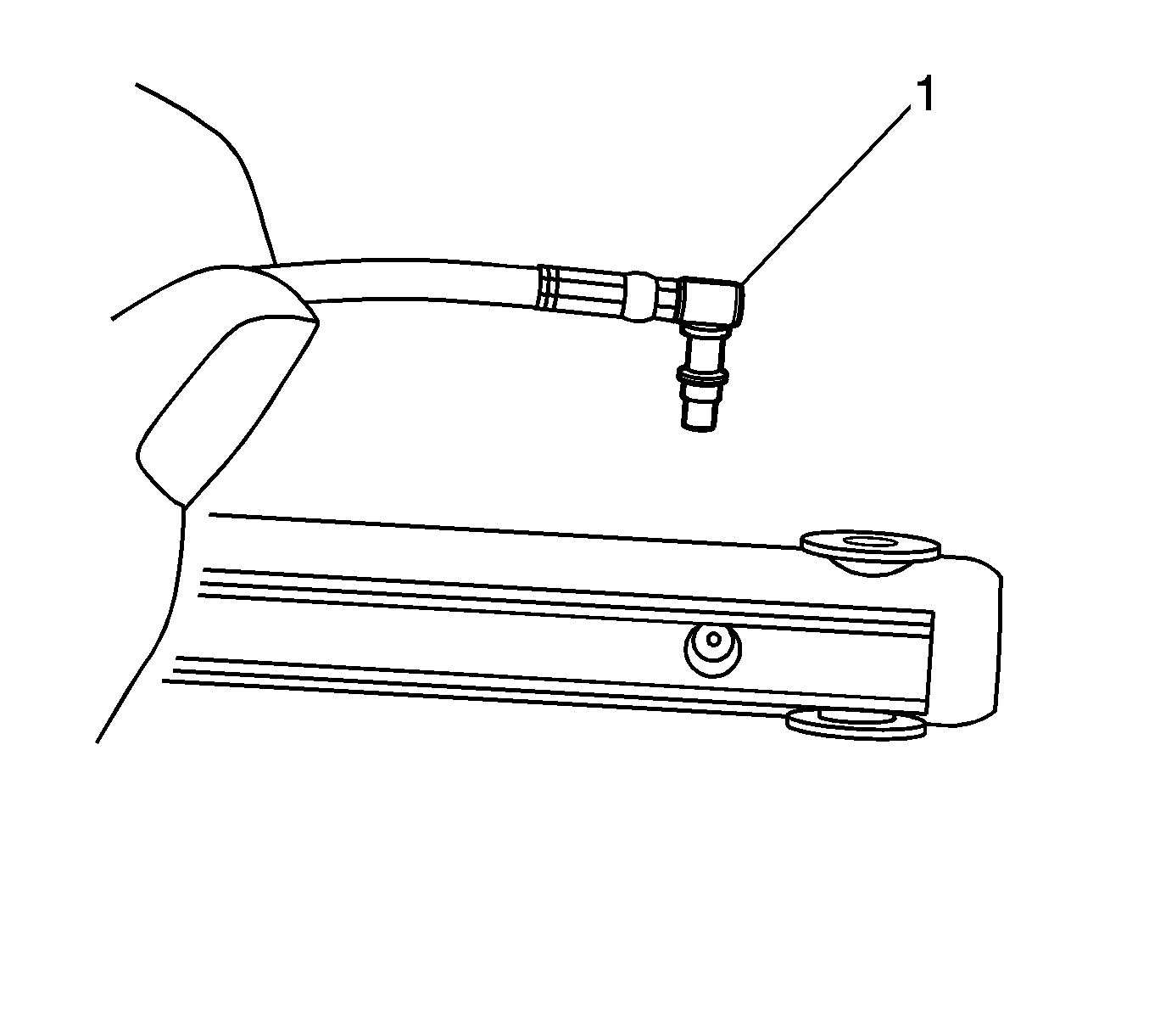
Important: After you have removed the cylinder hose, DO NOT move the cylinder rod. This will cause fluid to squirt out of the ports.
- Remove the cylinder hose (1). Use a clean shop towel to control any hydraulic fluid leakage.
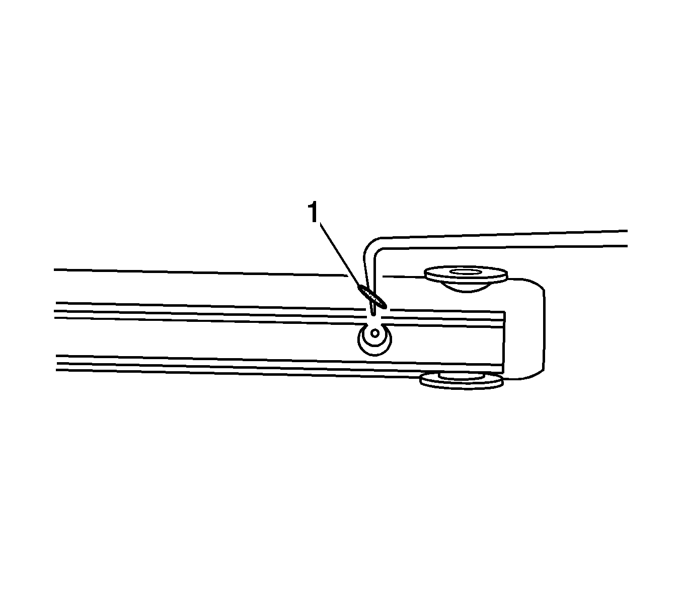
- Remove the cylinder hose O-ring (1) from the cylinder.
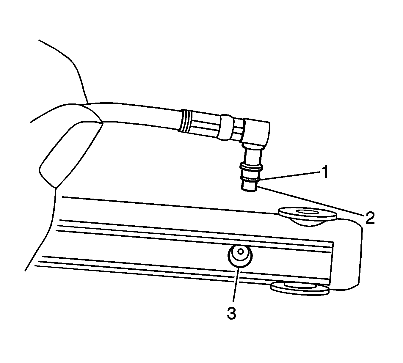
- Install a new O-ring (1) onto the cylinder hose (2).
- Install the cylinder hose into the cylinder port (3). Press straight down on the hose until the hose is fully seated in the cylinder.
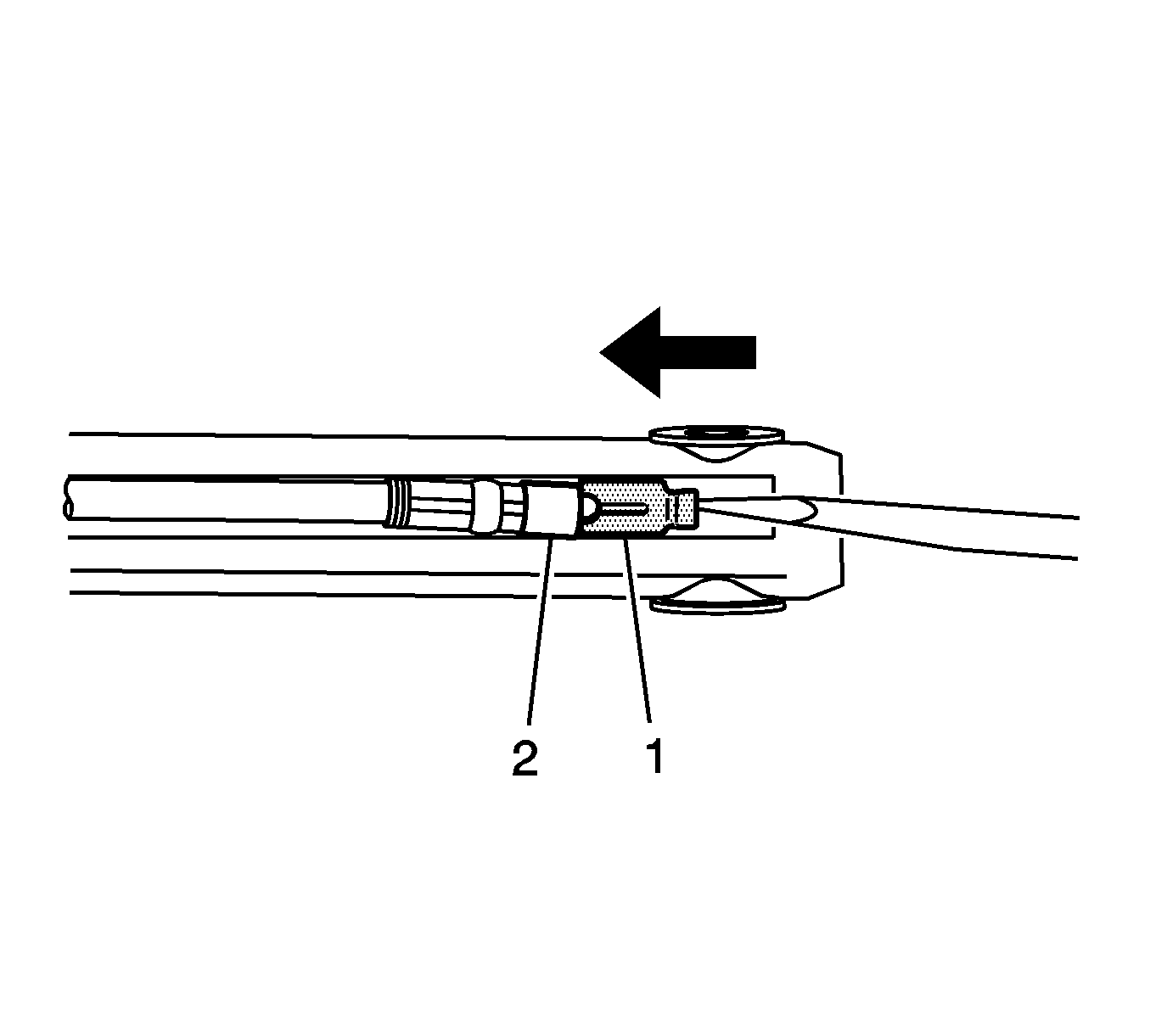
- Install the cylinder hose retainer clip (1). Inspect the retainer clip to ensure that the clip is fully seated around the
hose.
- Repeat the replacement procedure for the second hose.
- Install the appropriate hydraulic cylinder to the mounting location. Refer to
Folding Top Hydraulic Cylinder Replacement
.

- Install the reservoir filler plug (1).
- Position the hydraulic pump to the correct mounting location.

- Tighten the hydraulic pump bracket nuts.
Tighten
Tighten the bolts to 18 N·m (13 lb ft).

- Install the 2 electrical connectors from the hydraulic pump.

- Install the 4 electrical connectors to the hydraulic pump solenoids as follows:
| • | Connector C 4 Green, to solenoid valve 4 (with Red and Green CKT) |
| • | Connector C 3 Orange, to solenoid 3 (with a LT Blue CKT) |
| • | Connector C 1 Green to solenoid valve 1 (with WHITE CKT) |
| • | Connector C 2 Blue to solenoid valve 2 (with Dark BLUE CKT) |
| • | Folding Top Pump with Motor (6) |
- Remove the protective covering.
- Connect the battery. Refer to
Battery Negative Cable Disconnection and Connection
in Engine Electrical.
- Close the stowage compartment lid.
- Bleed the hydraulic system. Refer to
Folding Top Hydraulic System Bleeding Procedure
.
- Inspect the hydraulic system for fluid leaks.
- Inspect the hydraulic system fluid level and add fluid as needed. Refer to
Folding Top Fluid Addition
.
- Inspect the folding top for proper operation. Refer to
Power Folding Top Description and Operation
.


