For 1990-2009 cars only
Brake Pedal Assembly Replacement Left-Hand Drive
Removal Procedure
- Remove the stop lamp switch. Refer to Stop Lamp Switch Replacement .
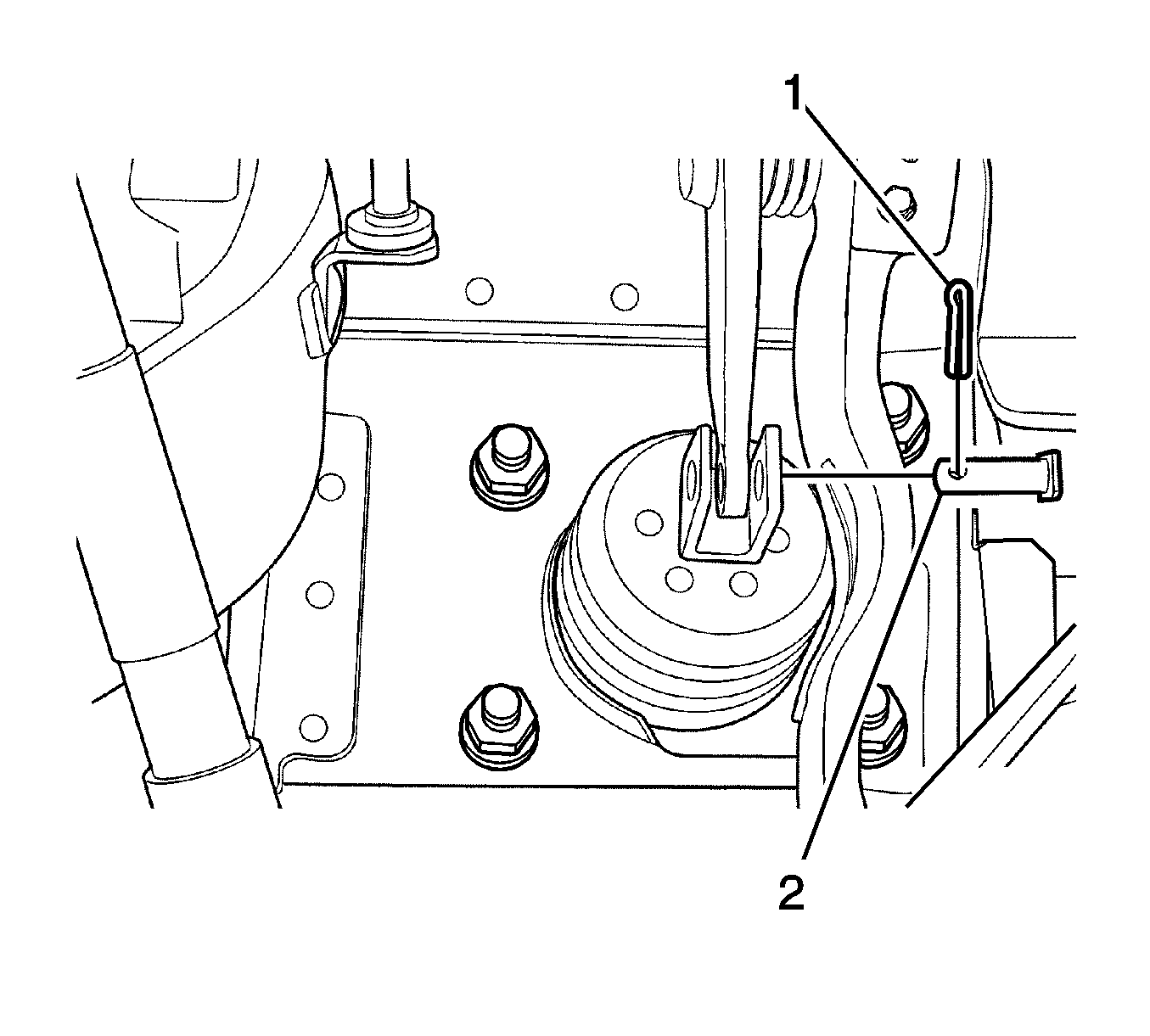
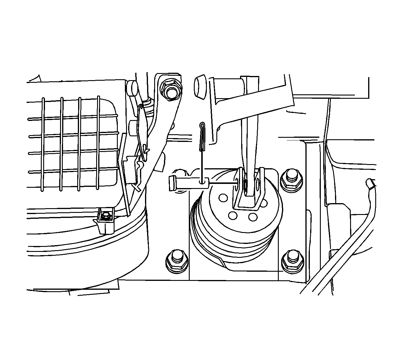
- Remove and discard the cotter pin (1).
- Remove the clevis pin (2).
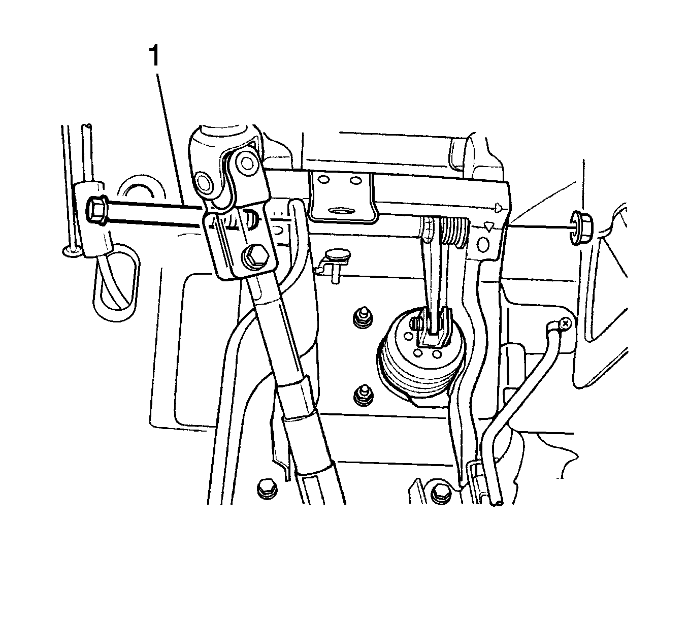
- Remove the brake pedal nut and the brake pedal bolt (1).
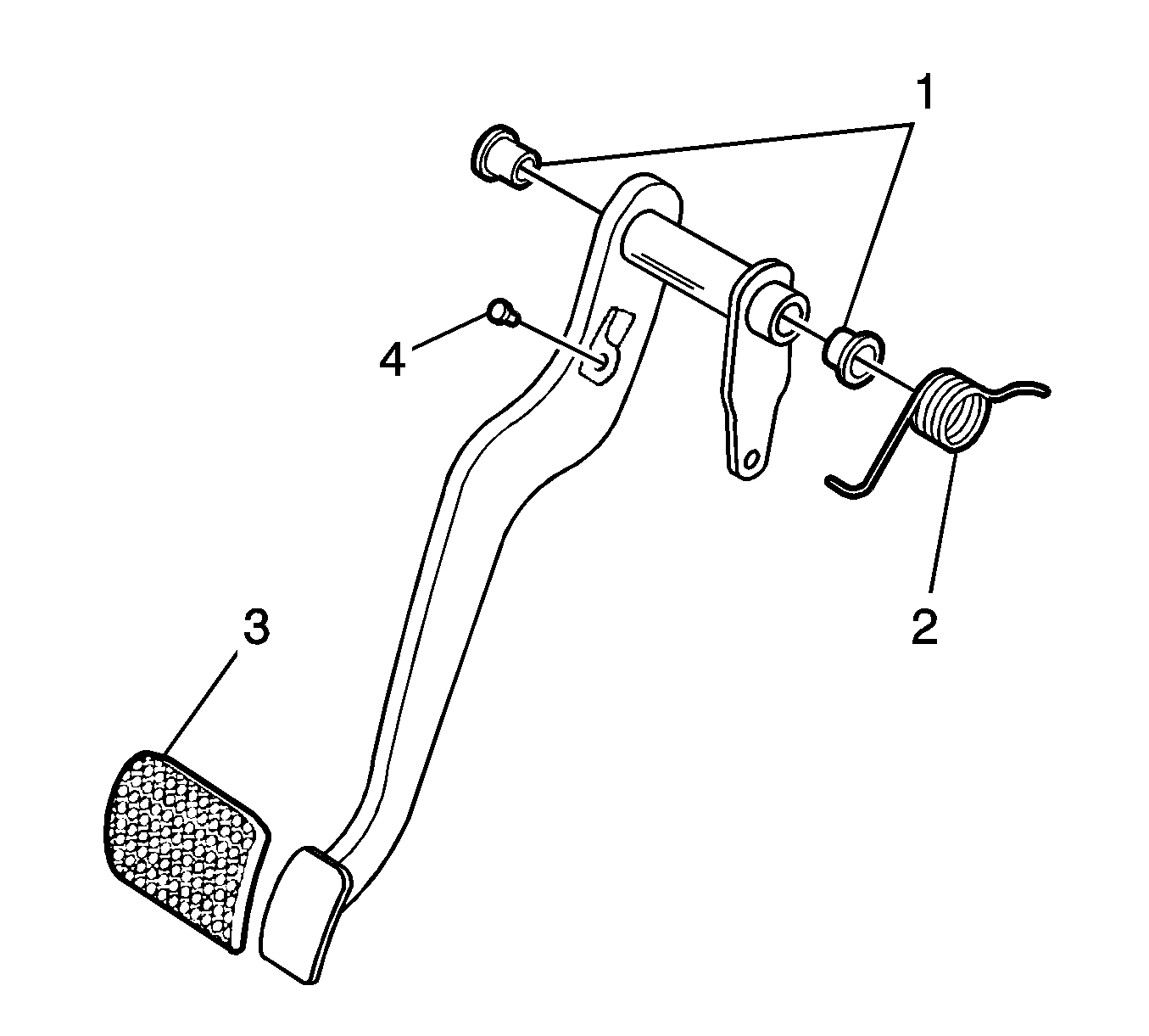
- Remove the brake pedal spring (2).
- Remove the bushings (1).
- Remove the cushion (4).
- Remove the brake pedal pad (3).
- Remove the brake pedal.
Installation Procedure
- Install the brake pedal pad (3).
- Install the cushion (4).
- Install the bushings (1).
- Install the brake pedal spring (2).
- Install the brake pedal to the pedal bracket with a bolt (1) and a nut.
- Install the clevis pin (2).
- Install a NEW cotter pin (1).
- Install the stop lamp switch. Refer to Stop Lamp Switch Replacement .

Notice: Refer to Fastener Notice in the Preface section.

Tighten
Tighten the bolt and the nut to 18 N·m
(13 lb ft).

Brake Pedal Assembly Replacement Right-Hand Drive
Removal Procedure
- Remove the instrument panel assembly. Refer to Instrument Panel Assembly Replacement in Instrument Panel, Gages, and Console.
- Disconnect the brake pedal rod from the power booster. Refer to Power Vacuum Brake Booster Replacement .
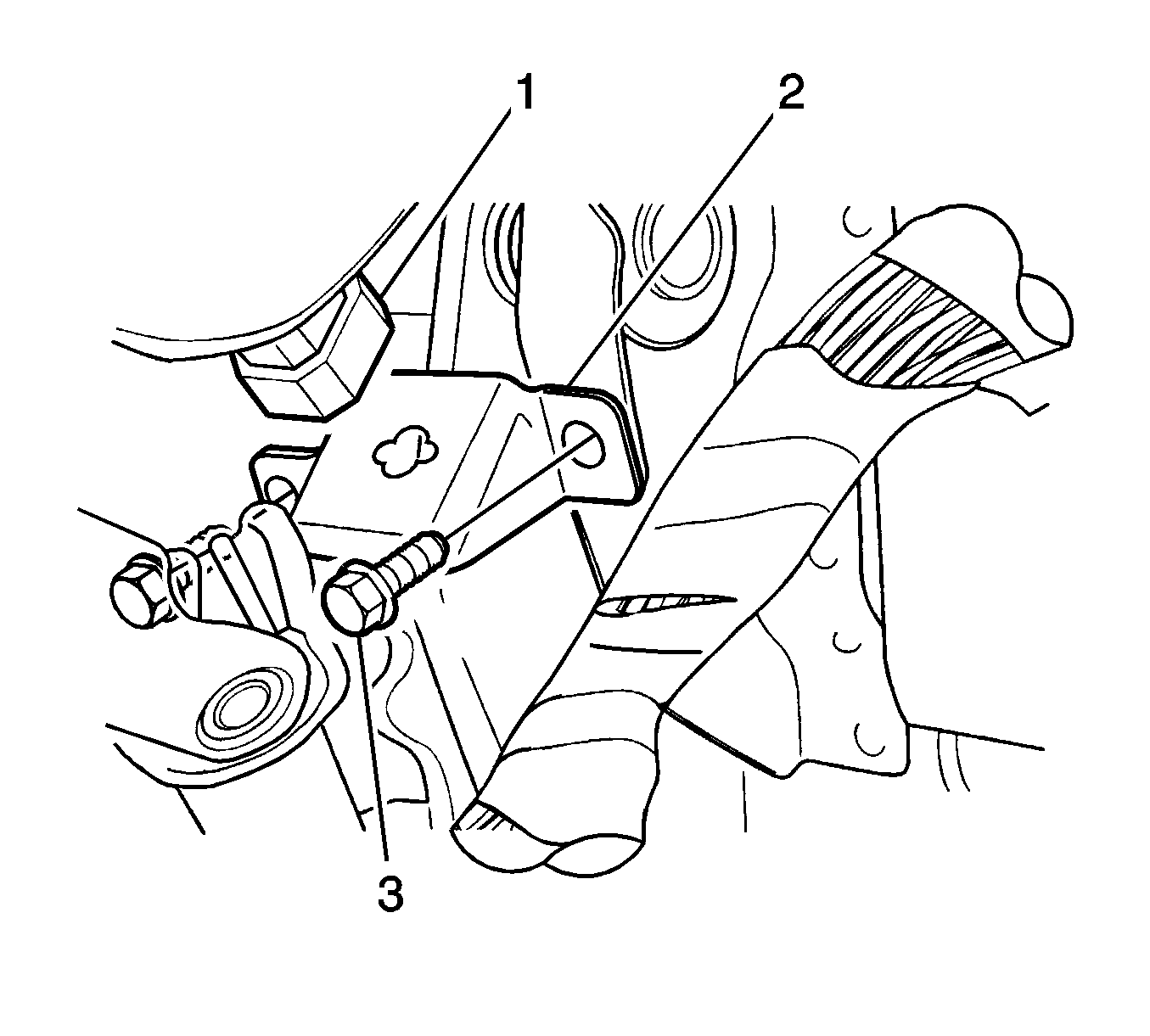
- Remove the stop lamp switch (1).
- Remove the bolts (3).
- Remove the stop lamp switch bracket (2).
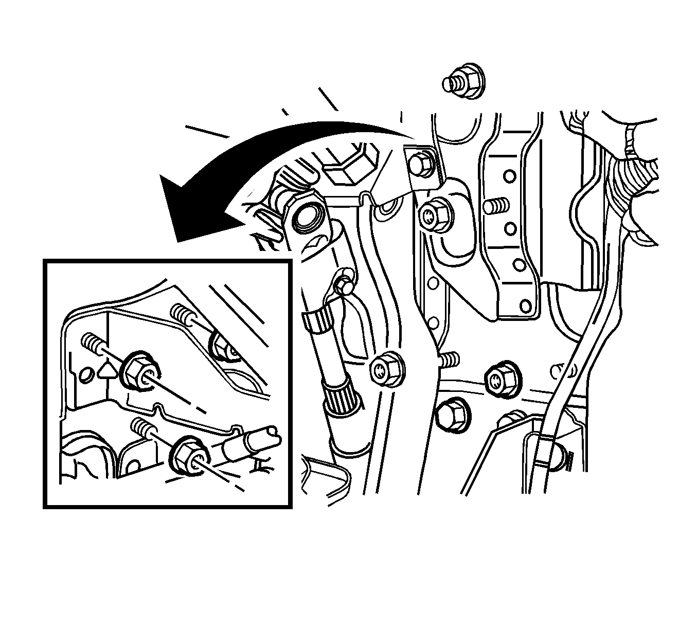
- Remove the bolts mounting brake pedal bracket (2).
- Remove the nuts mounting brake pedal bracket (1).
- Remove the evaporative canister. Refer to Evaporative Emission Canister Replacement in Engine Controls.
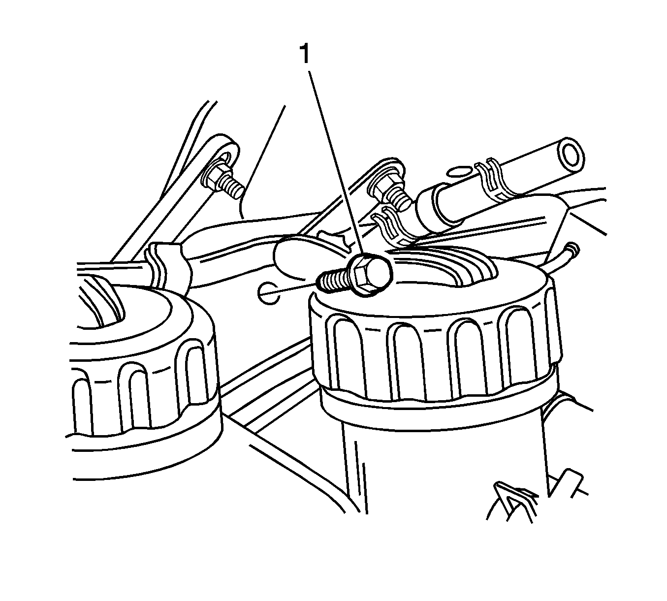
- Remove the bolt mounting brake pedal bracket in the engine compartment (1).
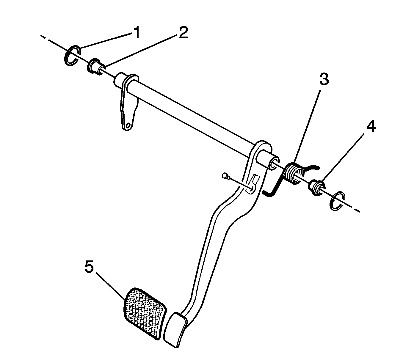
- Remove the brake pedal snap rings (1).
- Remove the bushings (2).
- Remove the brake pedal spring (3).
- Remove the cushion (4).
- Remove the brake pedal pad (5).
- Remove the brake pedal.
Installation Procedure
- Install the brake pedal with pad, spring, bushings, and cushion.
- Install the mounting brake pedal bracket bolt (1) in the engine compartment.
- Install the evaporative canister. Refer to Evaporative Emission Canister Replacement in Engine Controls.
- Install the brake pedal with the snap rings.
- Install the mounting brake pedal bracket bolts (2) and nuts (1).
- Install the stoplamp switch with the bracket and the bolts (1).
- Connect the brake pedal rod to the power booster. Refer to Power Vacuum Brake Booster Replacement .
- Install the instrument panel assembly. Refer to Instrument Panel Assembly Replacement in Instrument Panel, Gages, and Console.
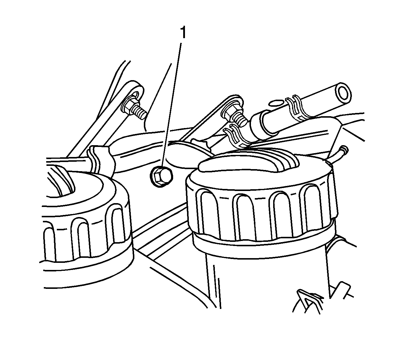
Notice: Refer to Fastener Notice in the Preface section.
Tighten
Tighten the bolt to 18-26 N·m
(13-20 lb ft).
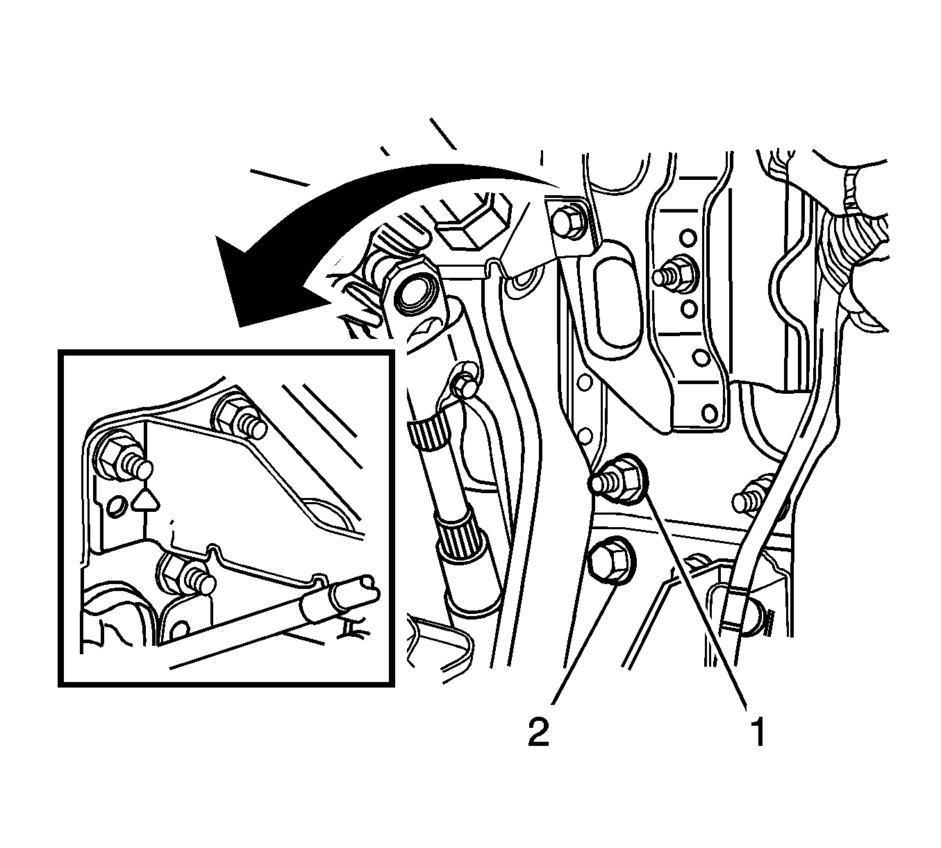
Tighten
| • | Tighten the bolts mounting brake pedal bracket to 18-26 N·m (13-20 lb ft). |
| • | Tighten the nuts mounting brake pedal bracket to 18-26 N·m (13-20 lb ft). |
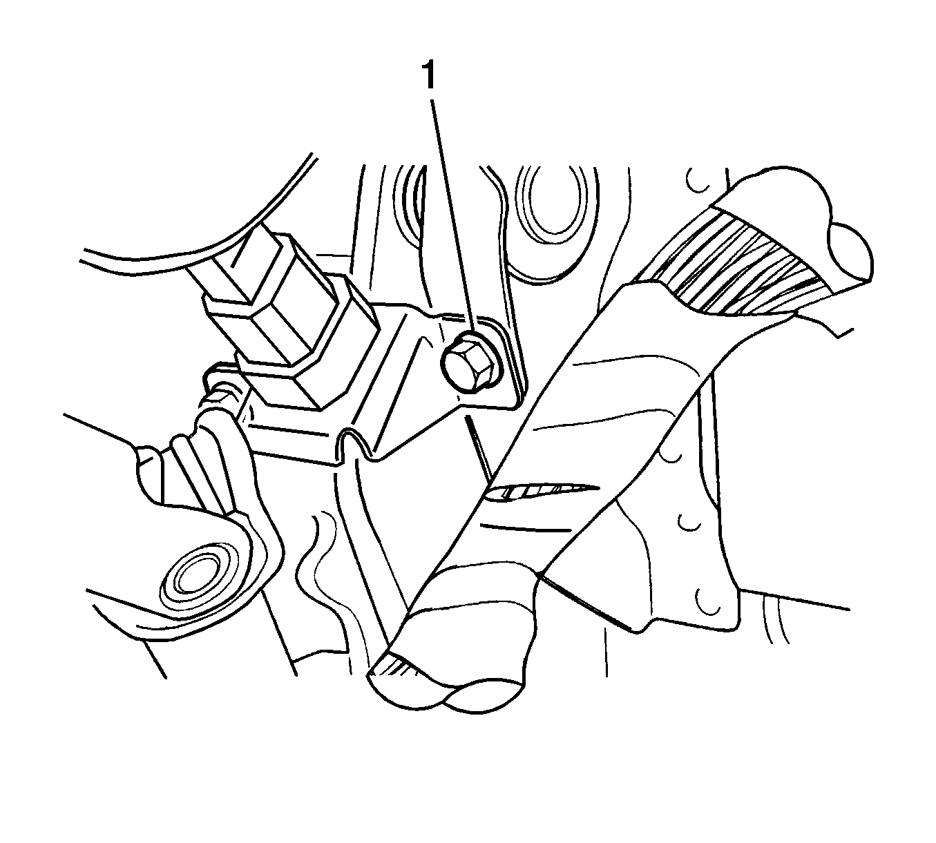
Tighten
Tighten the mounting bolts to 9-12 N·m
(80-106 lb in).
