Disassembly Procedure
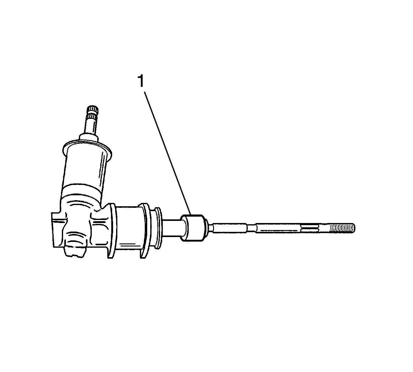
- Remove the rack and pinion steering assembly from the vehicle. Refer to Rack and Pinion Replacement .
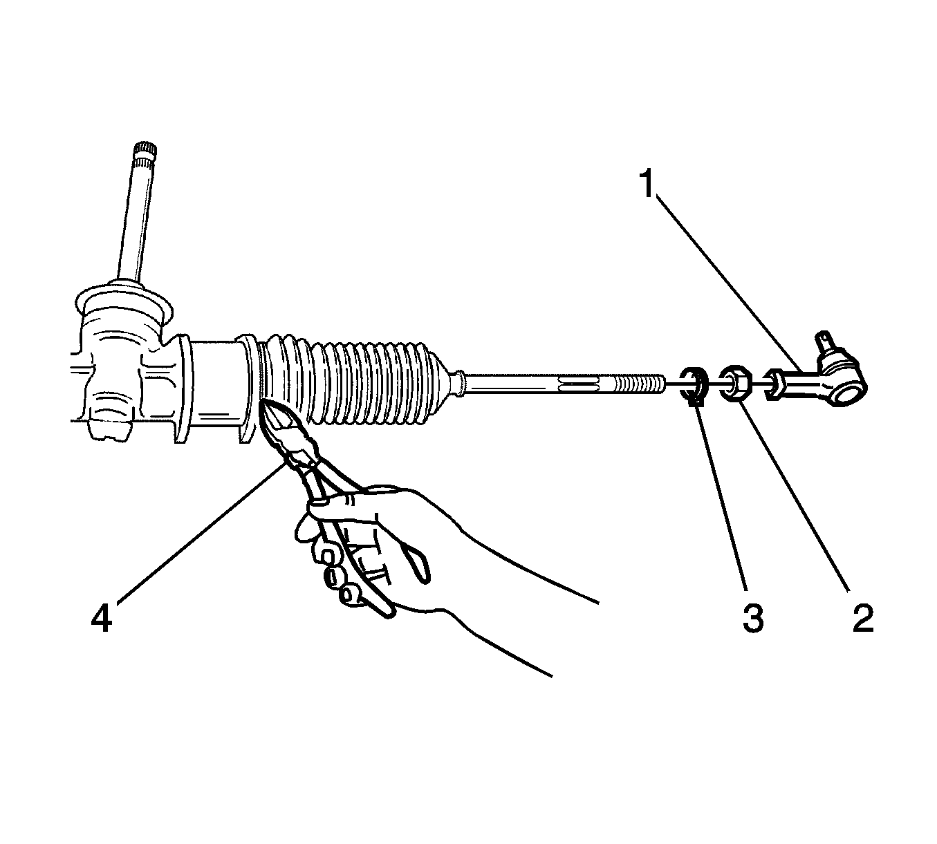
- Remove the tie rod end (1). Refer to Rack and Pinion Outer Tie Rod End Replacement .
- Remove the tie rod lock nut (2).
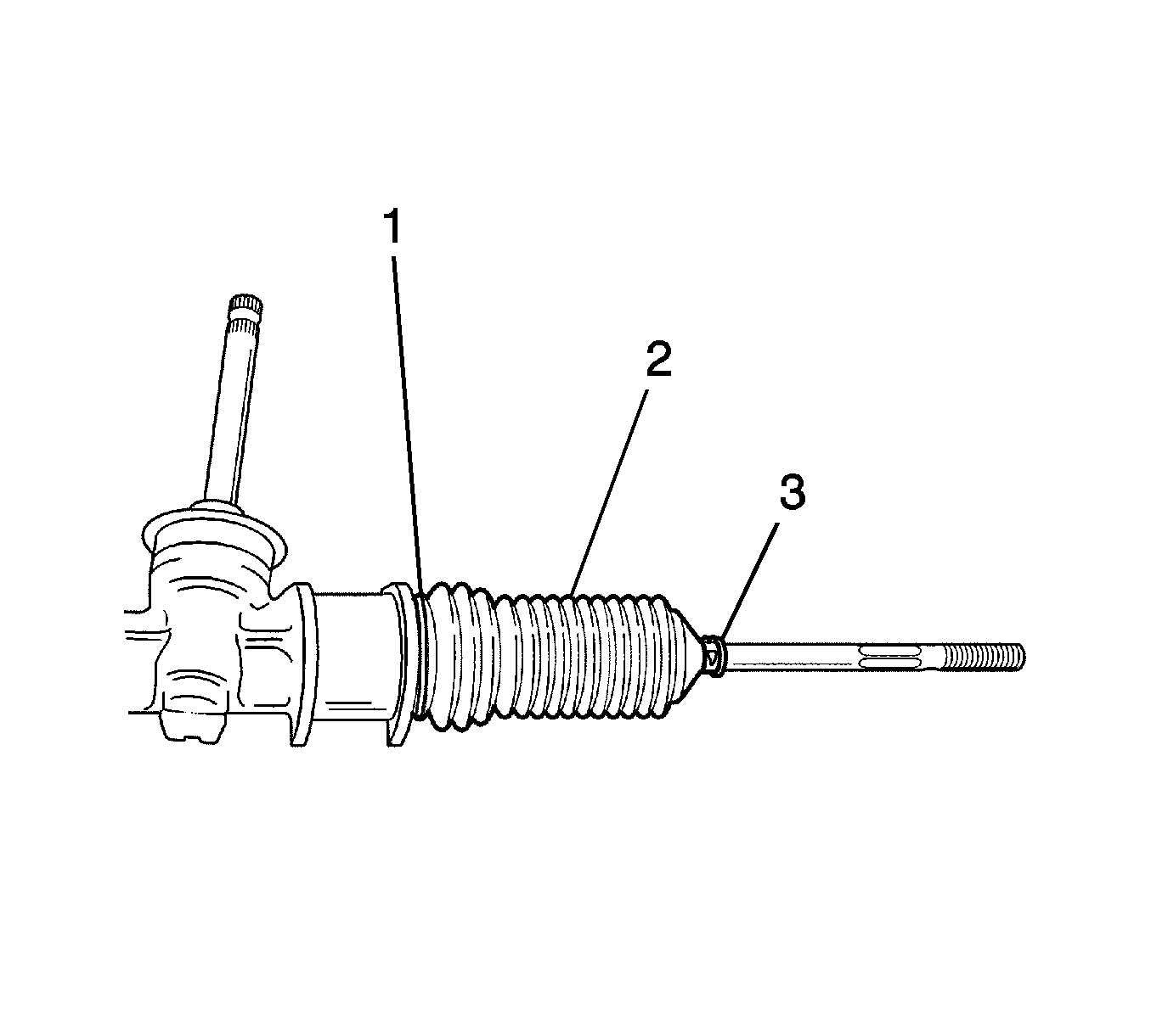
- Remove the rack and pinion boot clamp (3).
- Cut off the rack and pinion boot wire (4).
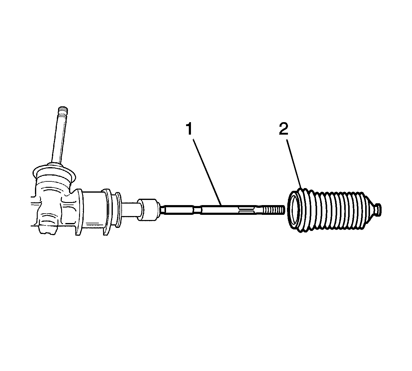
- Grease the tie rod (1).
- Remove the rack and pinion boot (2).
- Pull the rack gear perfectly from the steering gear housing by turning the pinion gear (1).
- Disconnect the shock damper ring from the tie rod ball joint (2).
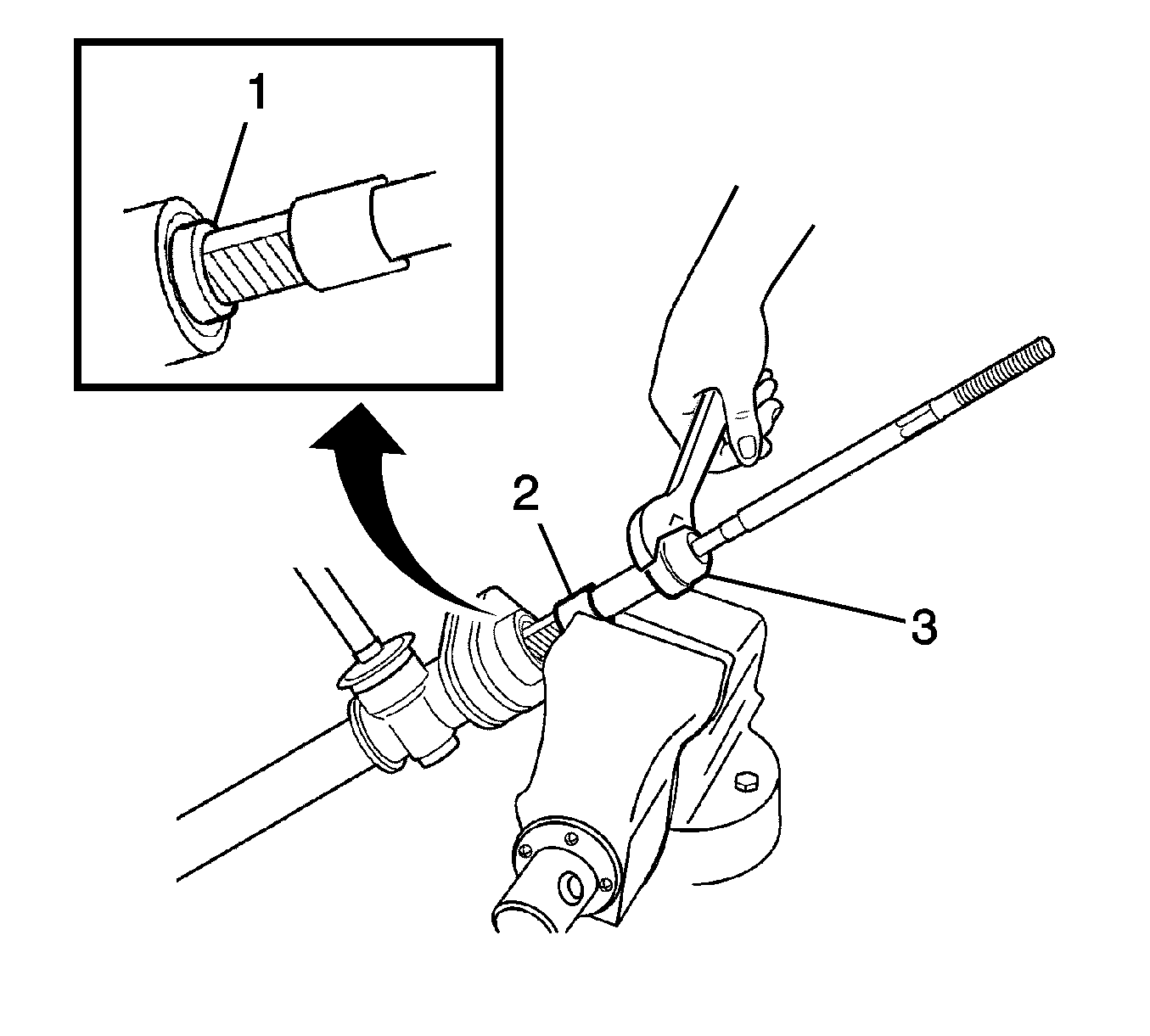
- Clamp the rack gear (1) in a vise.
- Remove the tie rod (1).
- Remove the shock damper ring (2).
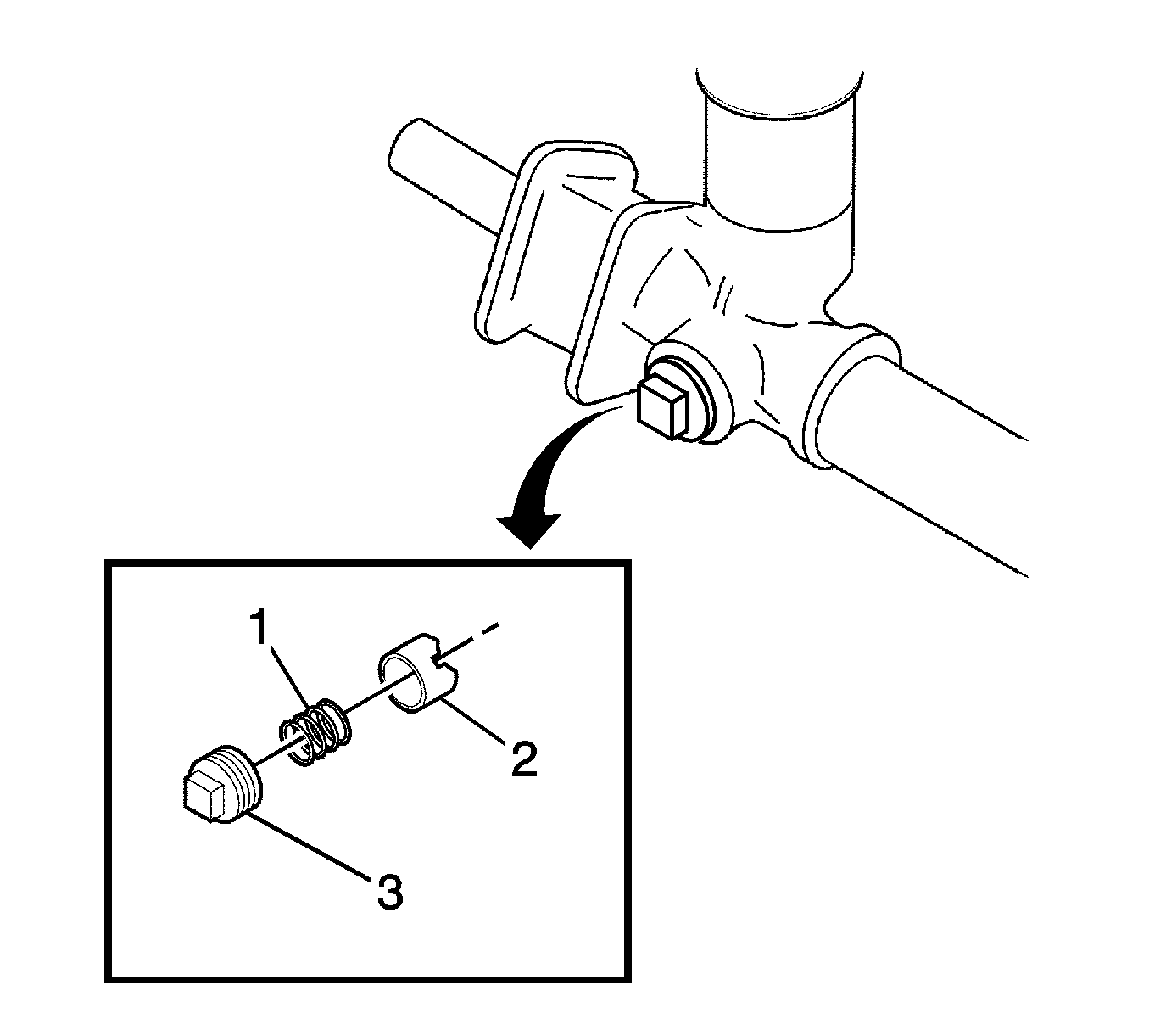
- Remove the adjuster plug (2).
- Remove the adjuster spring (1).
- Remove the rack bearing.
- Remove the dust cover (1).
- Remove the pinion plug (2).
- Remove the pinion and bearing assembly (1).
- Remove the rack gear (1) toward the driver side of the steering gear.
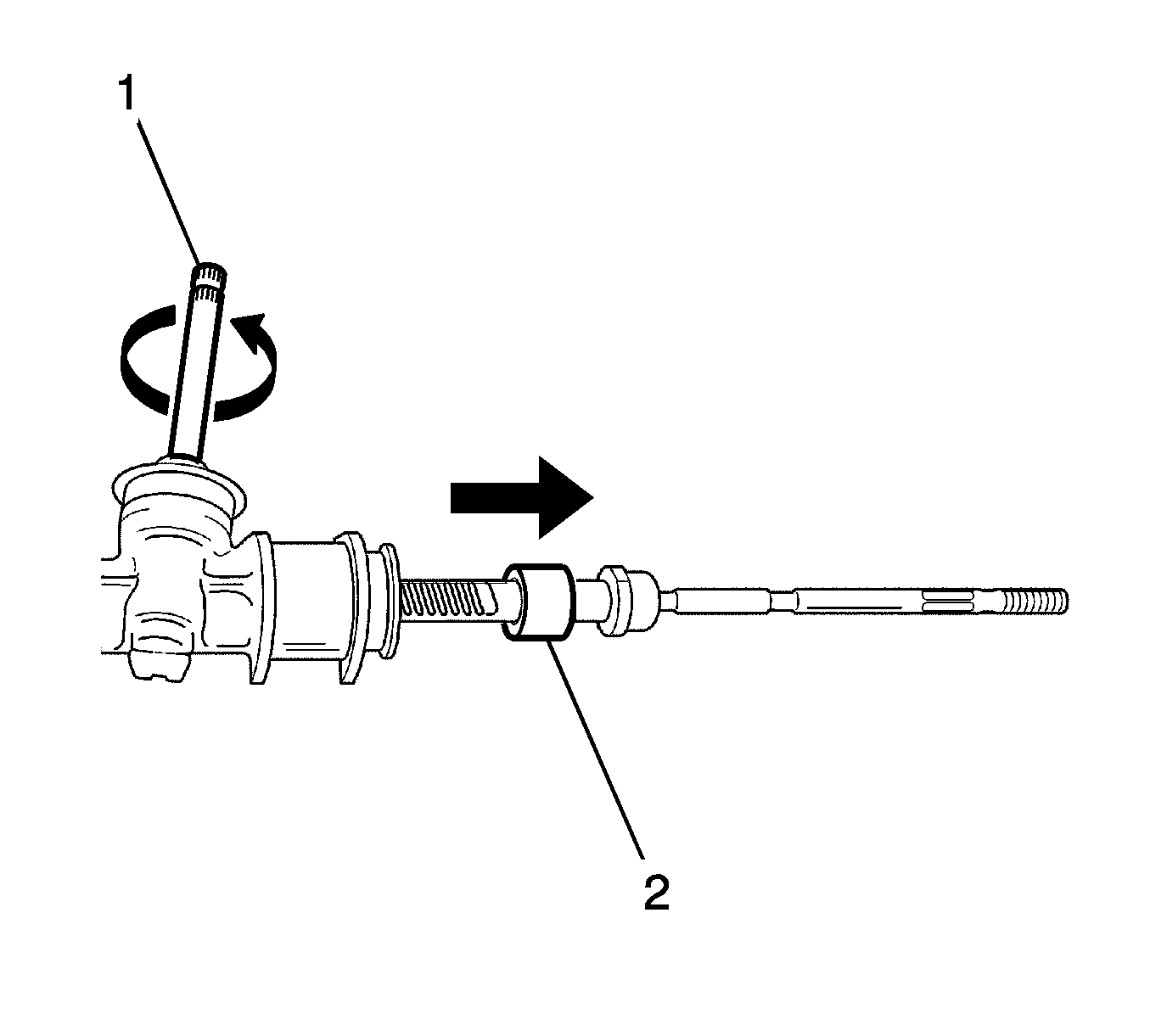
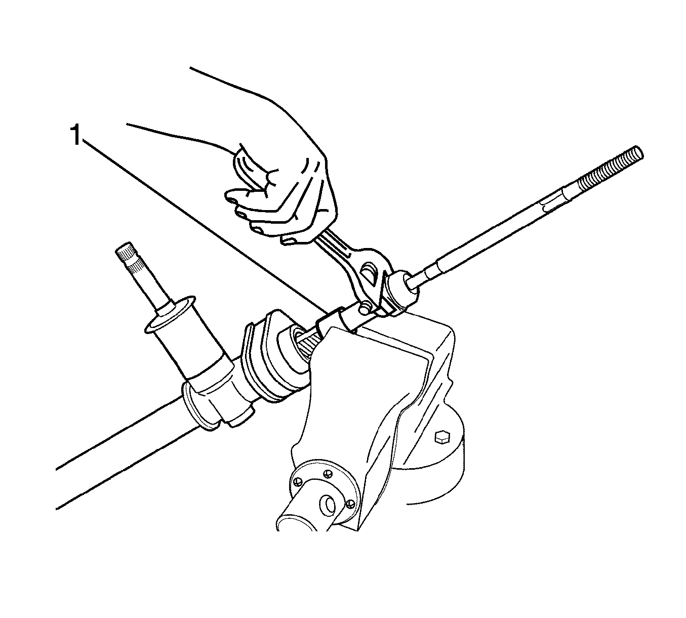
Important: Cover the rack gear with a cloth before clamping the rack gear.
Notice: Do not hold the rack gear between the jaws of the vise with more then one tooth contacting each jaw or the gear may be damaged.
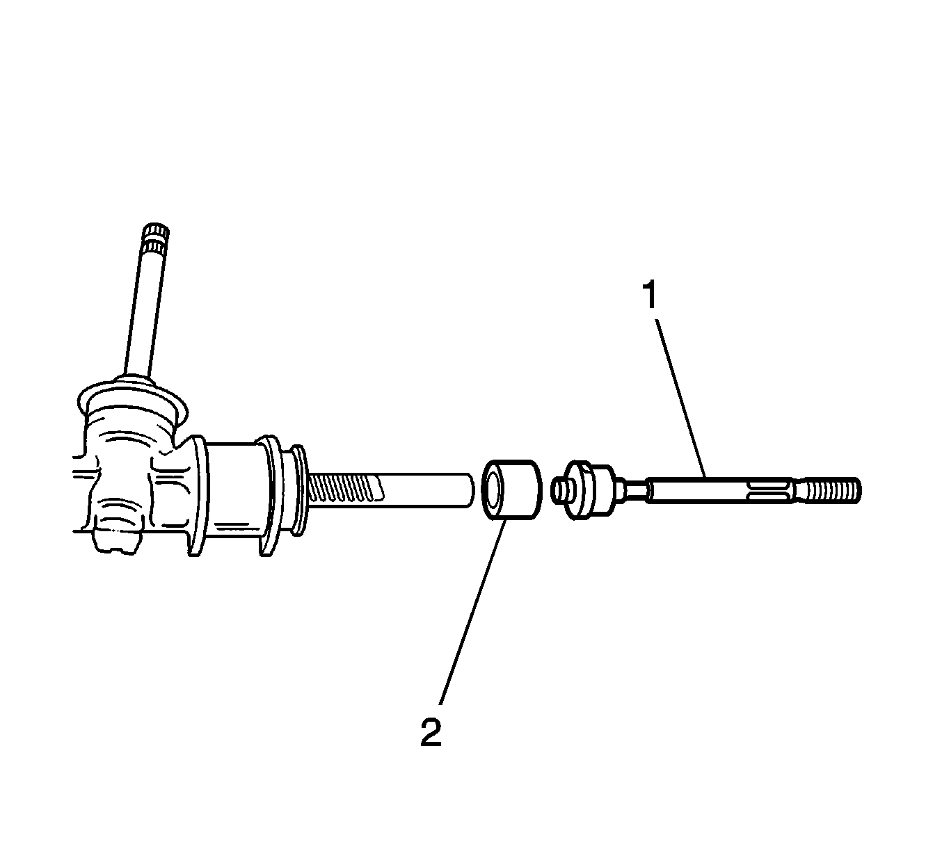
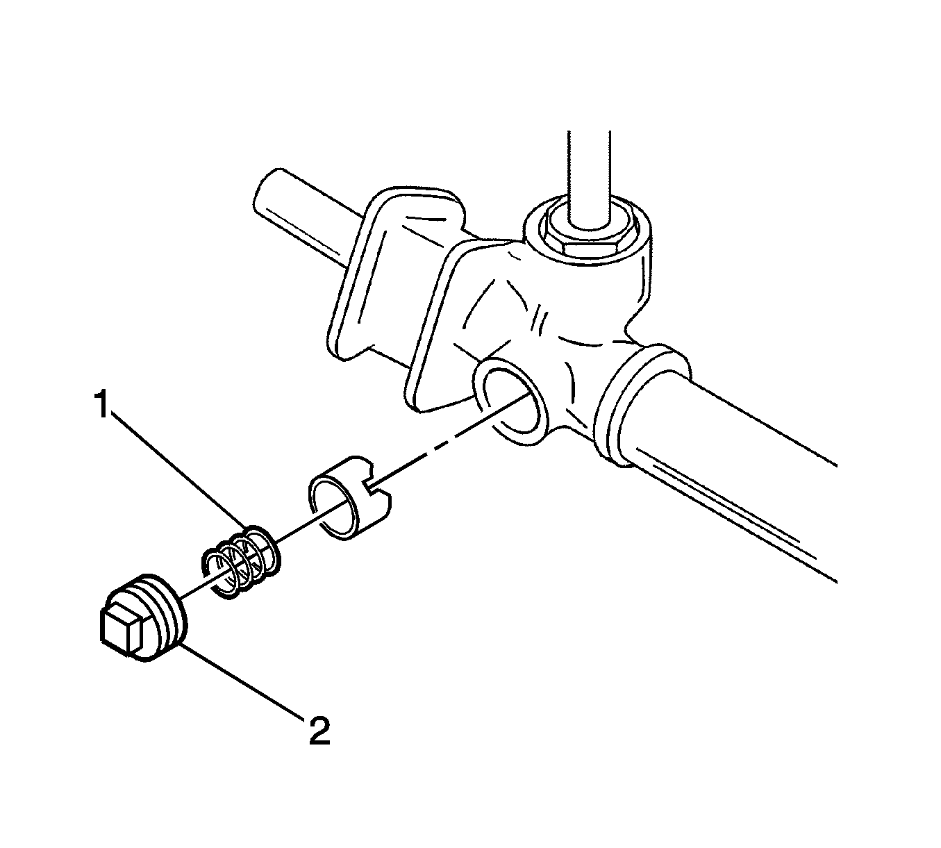
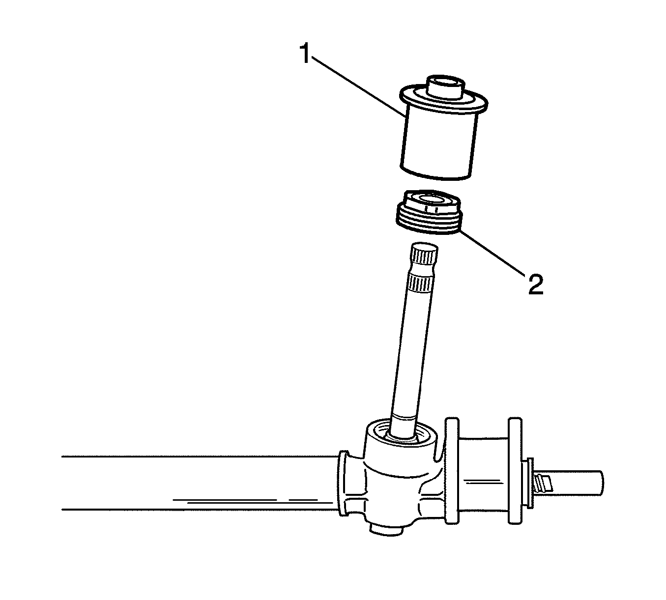
Important: Do not reuse the removed pinion plug.
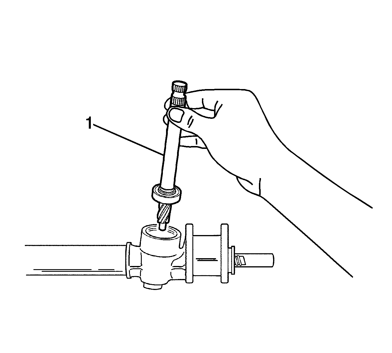
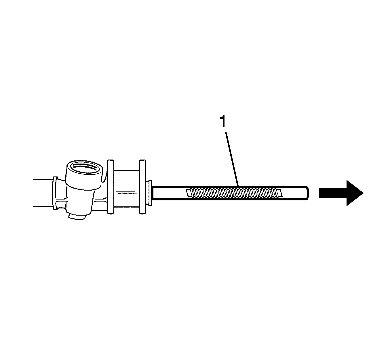
Notice: Remove the rack gear toward the driver side of the steering gear to prevent the bulk head in the steering gear housing from being damaging while installing and removing the rack gear.
Inspection Procedure
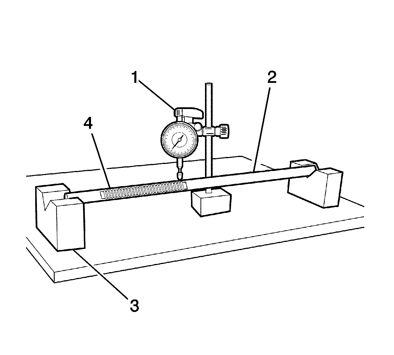
- Set the V-block on the plate (3).
- Set the rack gear on the V-block (2).
- Check the rack gear for deformation using a dial gage (1).
- Inspect the rack gear for wear and damage (4).
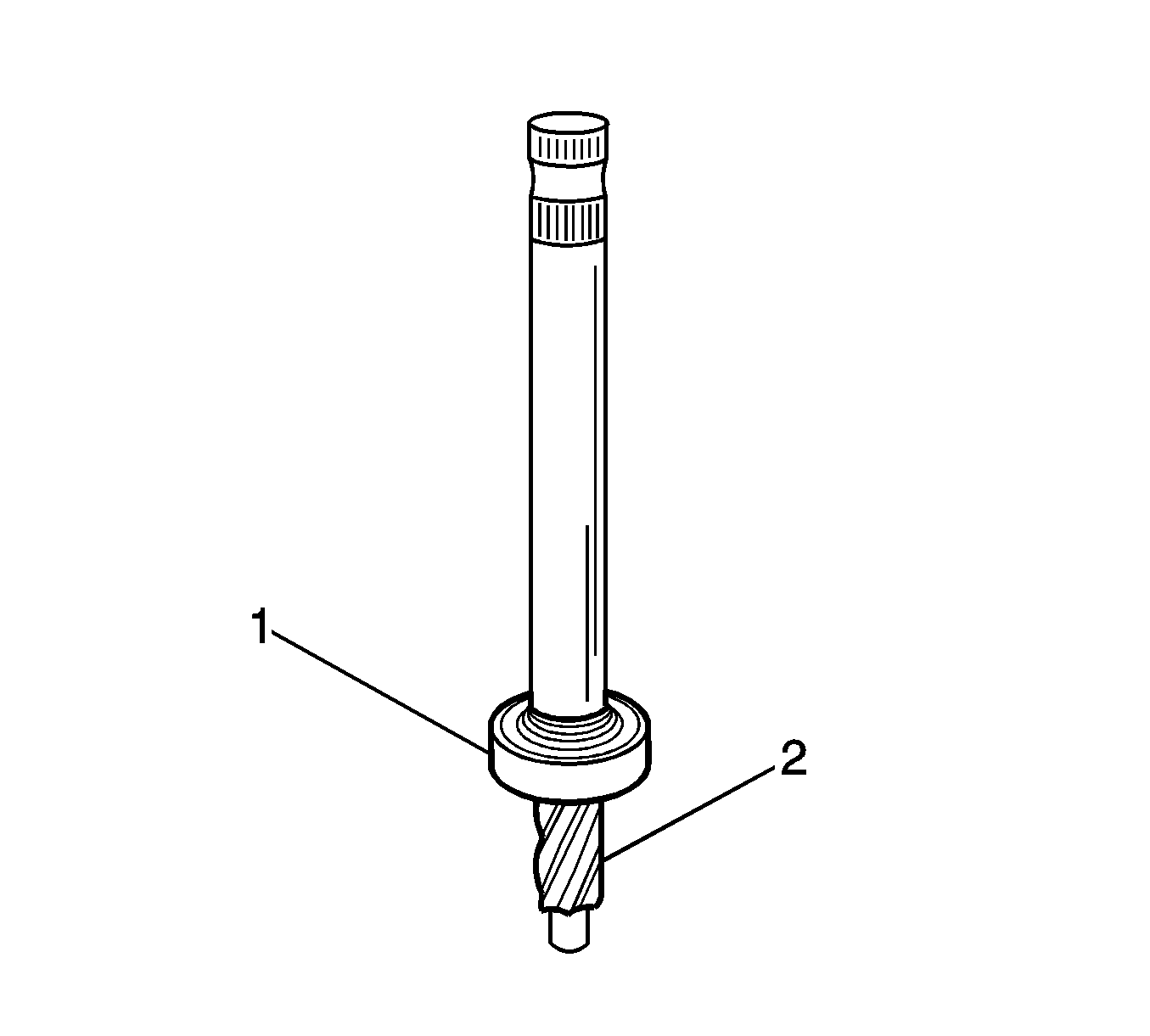
- Inspect the pinion gear for wear and damage (2).
- Inspect the bearing for loose and operation (1).
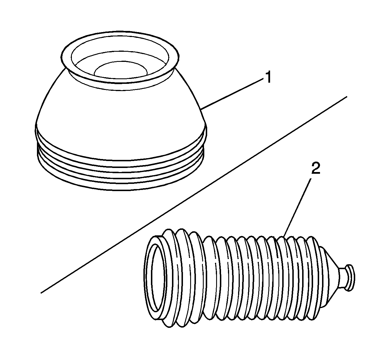
- Inspect the tie rod end boot for cracks and wear (1).
- Inspect the rack and pinion boot for cracks and wear (2).
- Inspect the steering gear housing (1) for cracks, deformation and wear.
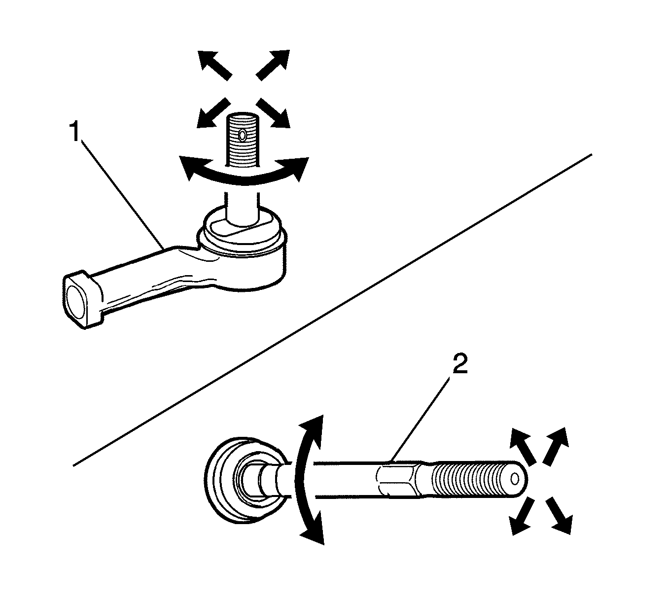
- Inspect the outer tie rod end ball joint operation (1).
- Inspect the tie rod ball joint for operation and tie rod damage (2).
- After inspecting the parts, replace the defective parts.

Assembly Procedure
- Clean all the parts removed.
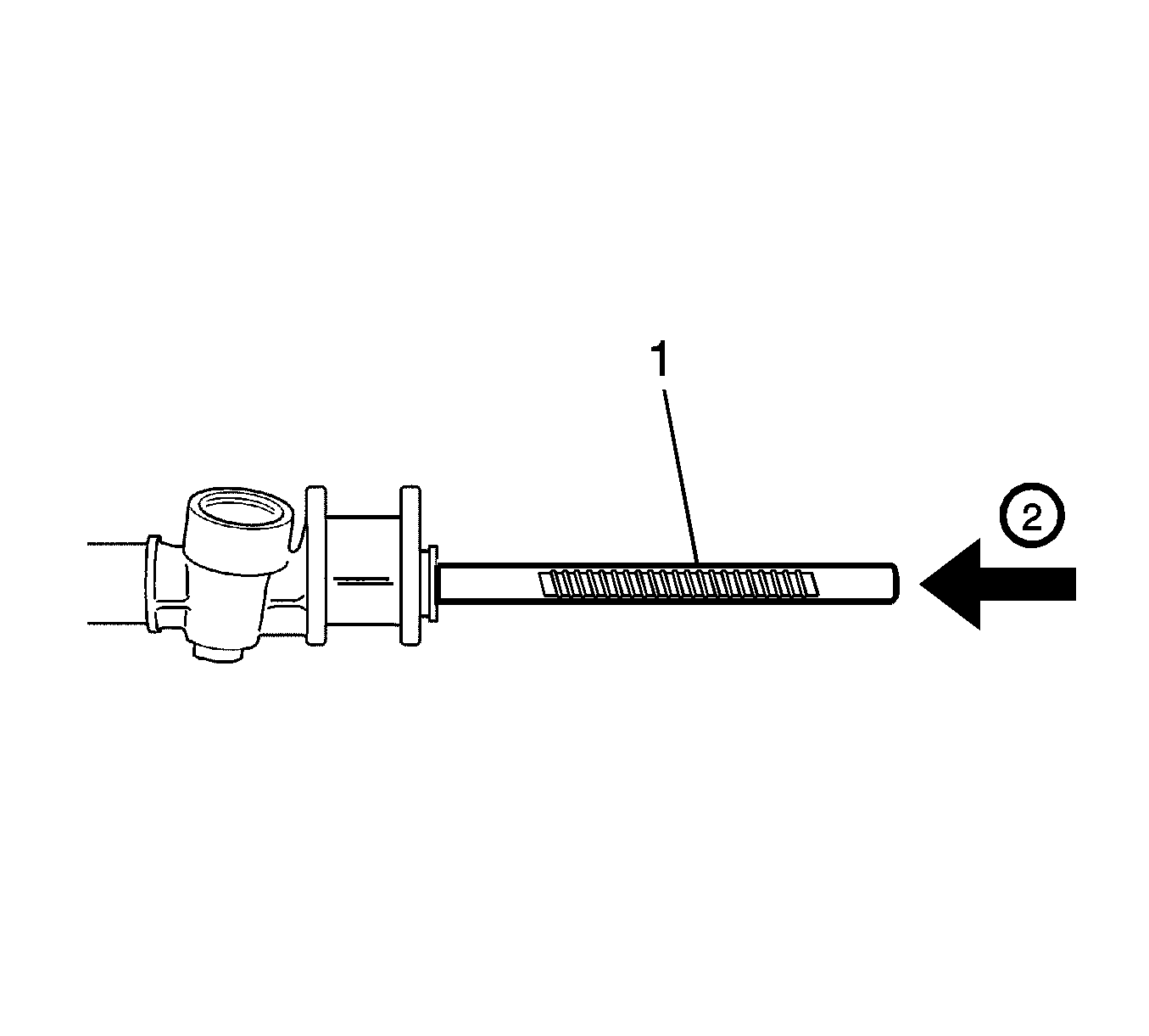
- Grease the rack gear (1).
- Insert the rack gear carefully (2).
- Set the rack in evenly (4).
- Grease the pinion and bearing assembly and steering gear housing surface.
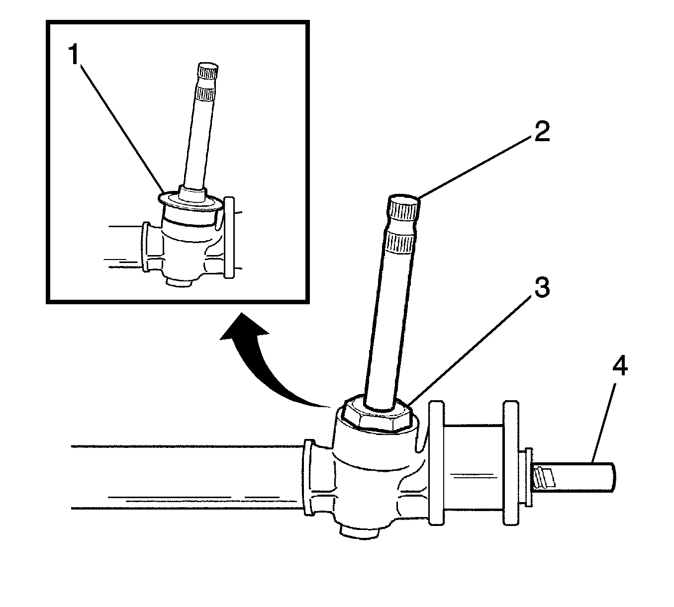
- Install the pinion and bearing assembly (2).
- Coat the pinion plug with LOCTITE.
- Install the pinion plug (3).
- Install the dust cover (1).
- Grease the rack bearing.
- Install the rack bearing (2).
- Install the adjuster spring (1).
- Tighten the adjuster plug softly (3).
- Install the shock damper ring to the rack gear (1).
- Clamp the rack gear (2) in a vise.
- Coat the teeth face of the tie rod with LOCTITE.
- Install the tie rod (3).
- Grease the tie rod ball joint.
- Install the shock damper ring to the tie rod ball joint (1).
- Install the rack and pinion boot (2).
- Install the rack and pinion boot wire clamp (1).
- Install the rack and pinion boot clamp (3).
- Install the tie rod end. Refer to Rack and Pinion Outer Tie Rod End Replacement .
- Install the rack and pinion steering gear assembly to the vehicle. Refer to Rack and Pinion Replacement .
- Adjust the free load of the steering gear. Refer to Steering Gear Adjustments .
Important: Coat all the turn, contact, and rub surfaces with grease.
Notice: Refer to Fastener Notice in the Preface section.
Tighten
Tighten the pinion plug to 40-60 N·m
(30-44 lb ft).
Important: Cover the rack gear with a cloth before clamping the rack gear.
Notice: Do not hold the rack gear between the jaws of the vise with more then one tooth contacting each jaw or the gear may be damaged.
Tighten
Tighten the tie rod to 18-120 N·m
(59-89 lb ft).
