Removal Procedure
- Remove the propeller shaft from the vehicle. Refer to
Two-Piece Propeller Shaft Replacement
and
Rear Propeller Shaft Replacement
.
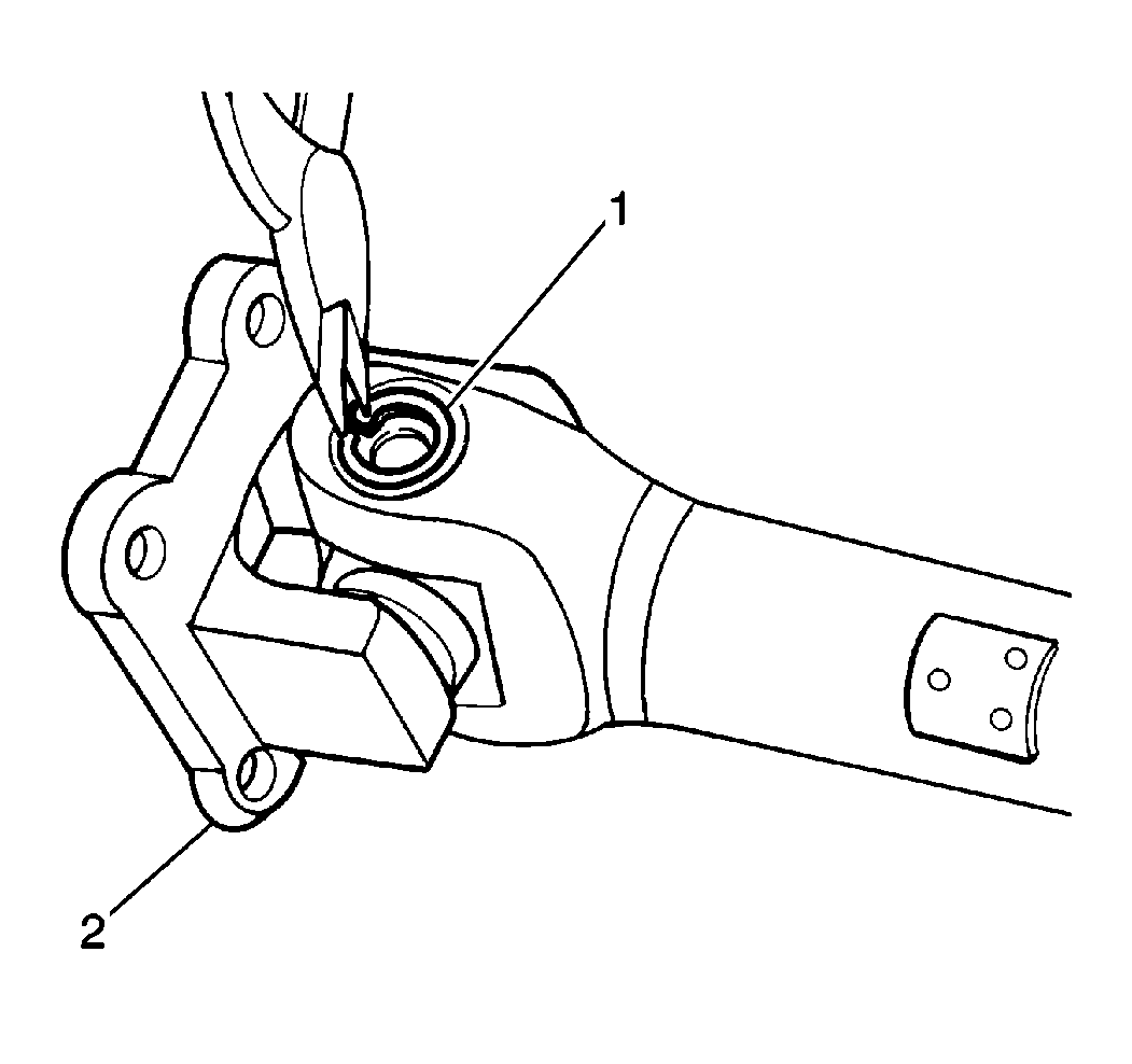
- Remove the 2 snap rings (1) from
the pinion flange yoke (2).
- Apply moisture displacing lubricant GM P/N 1052864 (Canadian P/N 992881),
or equivalent, to the outside of the pinion flange yoke (2) joint bearing caps.
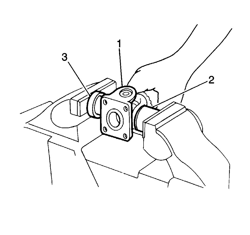
- Using an 18 mm (3) socket
in conjunction with a 24 mm (2) socket and a soft-jaw vise, place the
pinion flange yoke into the soft-jaw vise with 18 mm socket acting as a driver
and the 24 mm socket acting as a hollow support. Tighten the vise until the
bearing cap inside of the 24 mm socket has been exposed approximately 3-4 mm
(0.12-0.16 in).
- Remove the bearing cap from the pinion flange yoke by placing the exposed
portion of the bearing cap into a soft-jaw vise. Tap upwards on the pinion flange
yoke with a hammer until the bearing cap is free of the pinion flange yoke.
- Insert the 18 mm socket through the bearing cap opening in the
pinion flange yoke. Tap the socket gently with a hammer until the opposite bearing
cap is exposed approximately 3-4 mm (0.12-0.16 in).
- Remove the opposite bearing cap from the pinion flange yoke by placing
the exposed portion of the bearing cap into a soft-jaw vise. Tap upwards on the pinion
flange yoke with a hammer until the bearing cap is free of the pinion flange yoke.
- Remove the pinion flange yoke from the spider.
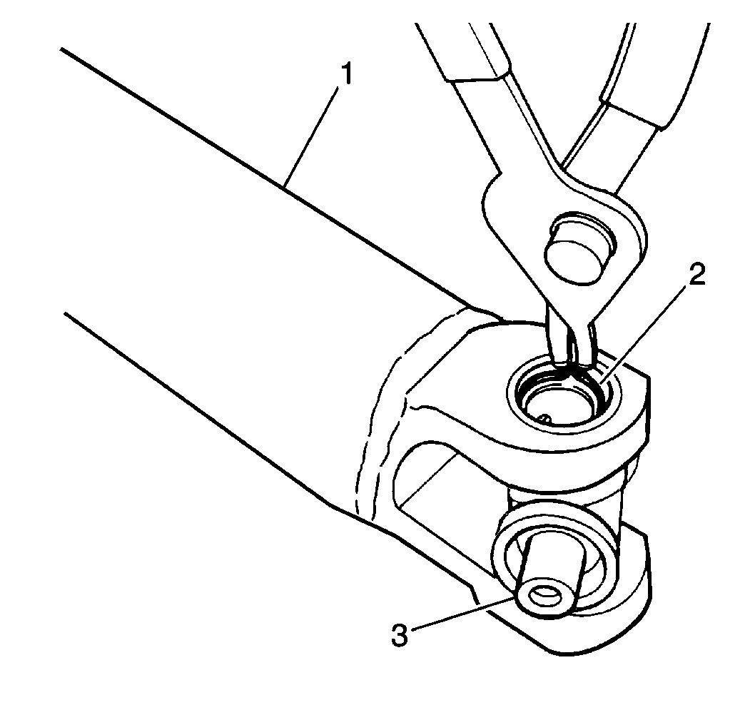
- Remove the 2 snap rings (2) from
the propeller shaft yoke.
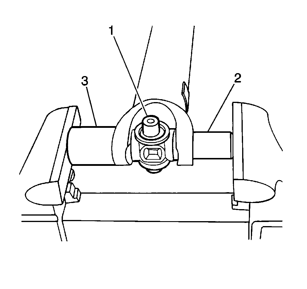
- Using an 18 mm (2) socket
in conjunction with a 24 mm (3) socket and a soft-jaw vise, place the propeller
shaft yoke into the soft-jaw vise with the 18 mm socket acting as a driver
and the 24 mm socket acting as a hollow support. Tighten the vise until the
bearing cap inside of the 24 mm socket has been exposed approximately 3-4 mm
(0.12-0.16 in).
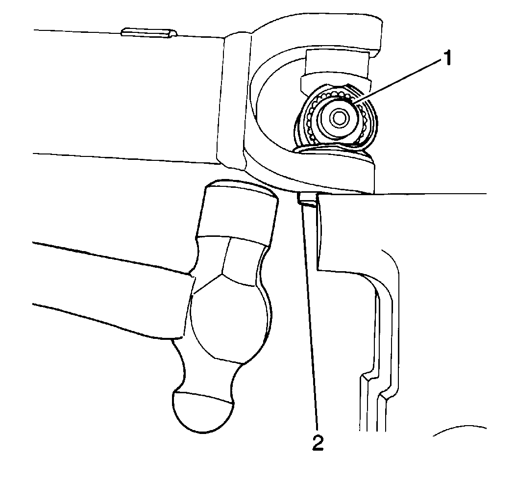
- Remove the bearing cap (2) from the
propeller shaft yoke by placing the exposed portion of the bearing cap into a soft-jaw
vise. Tap upwards on the propeller shaft yoke with a hammer until the bearing cap
is free of the propeller shaft yoke.
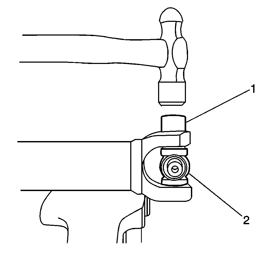
- Remove the opposite bearing cap by inserting
the 18 mm (1) socket through the bearing cap opening in the propeller shaft
yoke. Tap on the socket gently with a hammer until the opposite bearing cap is exposed
approximately 3- 4 mm (0.12-0.16 in).
- Remove the opposite bearing cap from the propeller shaft yoke by placing
the exposed portion of the bearing cap into a soft-jaw vise. Tap upwards on the propeller
shaft yoke with a hammer until the bearing cap is free of the propeller shaft yoke.
- Remove the spider from the propeller shaft yoke.
- Inspect the propeller shaft yoke for the following:
- Inspect the pinion flange yoke for the following:
| • | If the pinion flange yoke appears distorted or damaged, replace the pinion flange
yoke. |
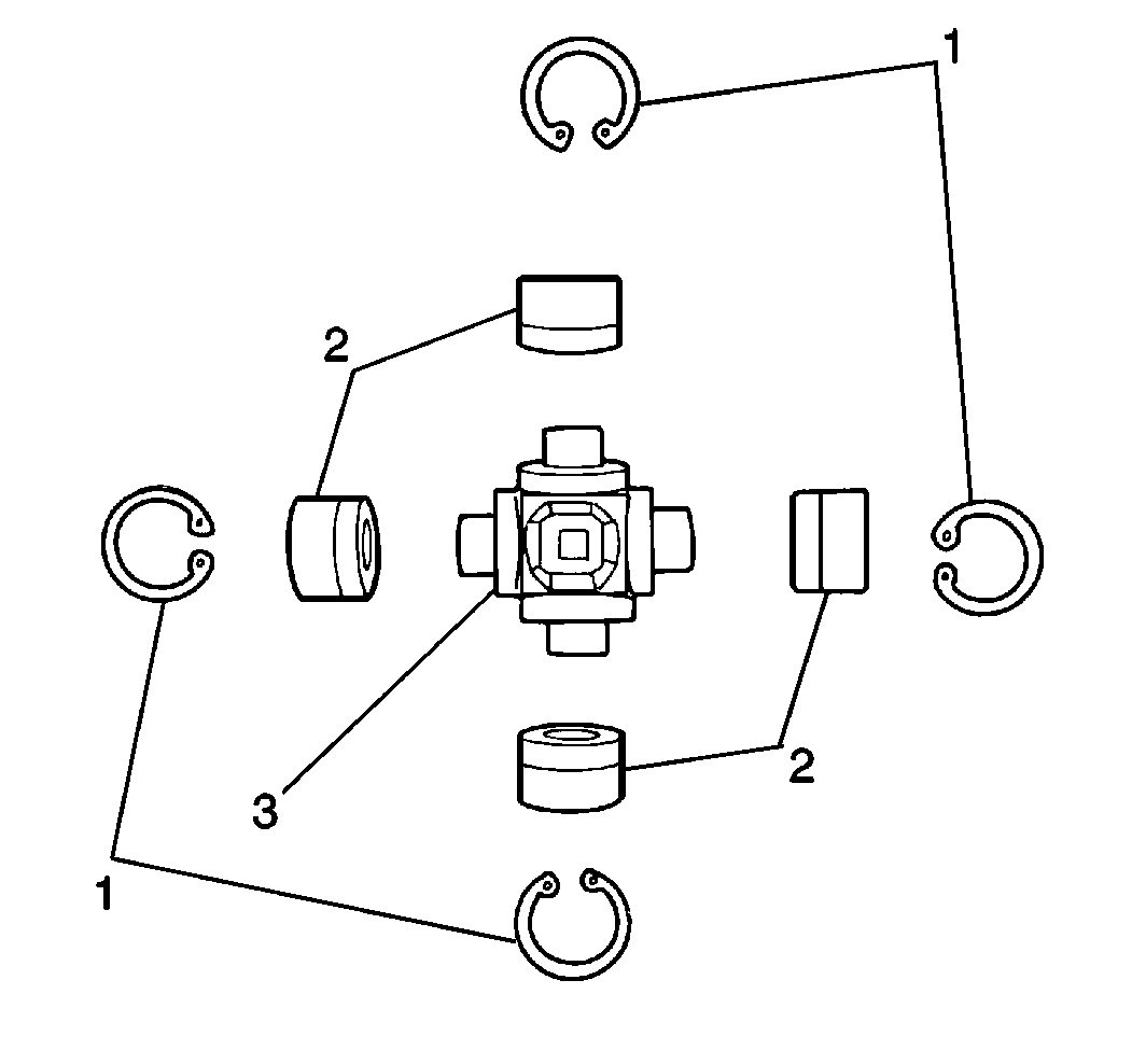
Important: If any unusual wear or damage is found on any component upon universal joint
inspection, do not attempt to repair or replace the component. Replace the universal
joint as an assembly.
- Inspect the bearing caps (2) for broken or missing needle bearings. If
the needle bearing appears missing or worn, replace the universal joint as an assembly.
- Inspect the bearing surfaces on the spider for flat spots or excessive
wear. If the bearing surfaces on the spider appear worn or flat, replace the universal
joint as an assembly.
Installation Procedure
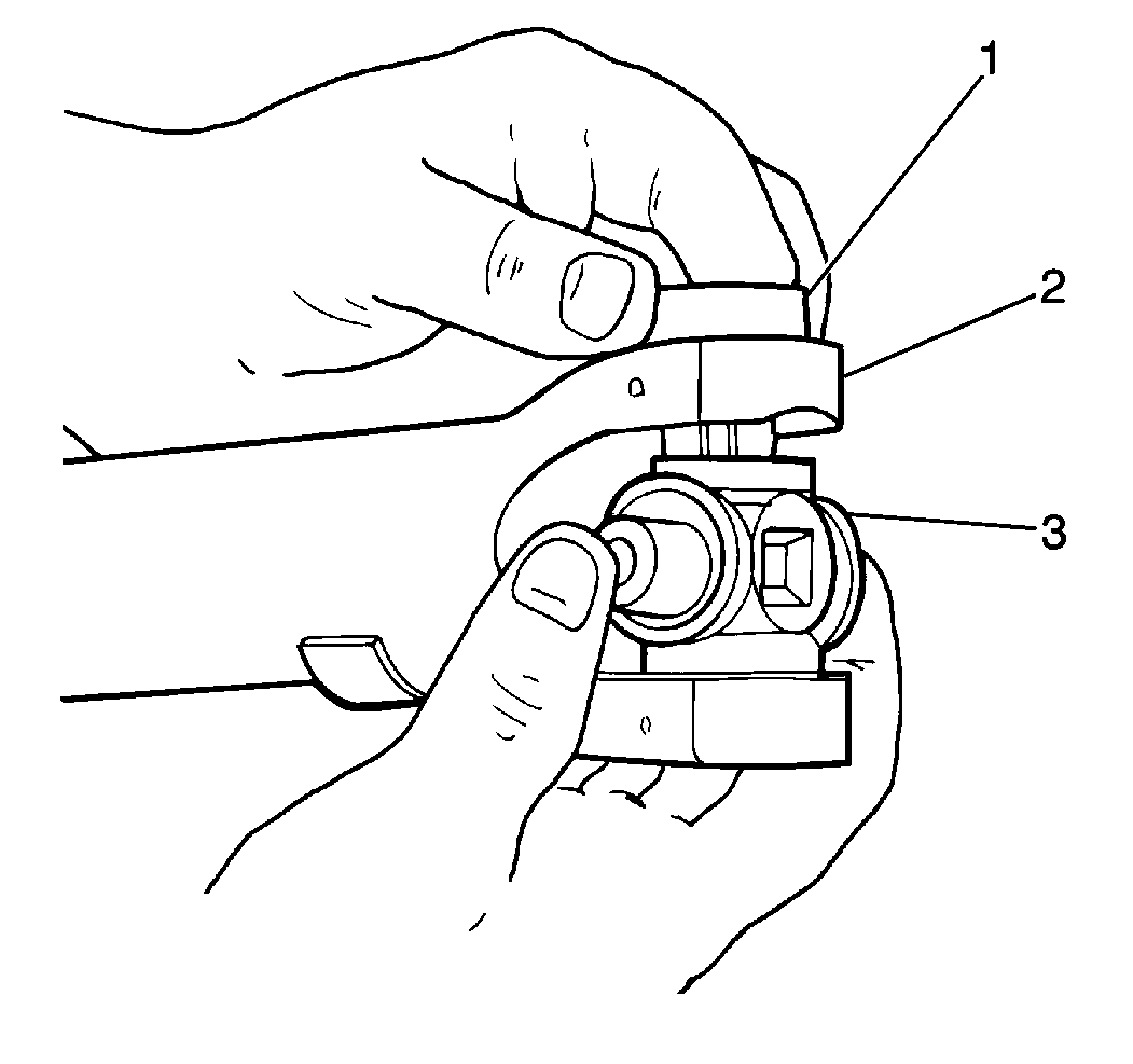
Notice: During bearing cap installation, make sure that the needle bearings
are correctly positioned. If the needle bearings become mispositioned during
installation, damage to the needle bearings and the spider will result.
- Install the spider (3) into the propeller shaft yoke (2).
- Apply moisture displacing lubricant GM P/N 1052864, or equivalent,
to the outside of the pinion flange yoke joint bearing caps.
- Install 1 bearing cap into the propeller shaft yoke. Tap gently
with a hammer in order to ensure the bearing cap fits smoothly over the pinion flange
yoke joint spider.
- Install the opposite bearing cap (1) into the propeller shaft
yoke. Tap gently with a hammer until a snap ring can be fitted.
- Install 1 snap ring into the propeller shaft yoke.
- Inspect the snap ring upon installation. Ensure the snap ring is completely
seated and firm.
- Using an 18 mm socket in conjunction with a 24 mm socket
and a soft-jaw vise, place the propeller shaft yoke into the soft-jaw vise with the
18 mm socket acting as a driver and the 24 mm socket acting as a hollow
support. Tighten the vise until the opposite bearing cap is pressed into the propeller
shaft yoke so that a snap ring can be fitted.
- Install 1 snap ring into the propeller shaft yoke.
- Inspect the snap ring upon installation. Ensure the snap ring is completely
seated and firm.
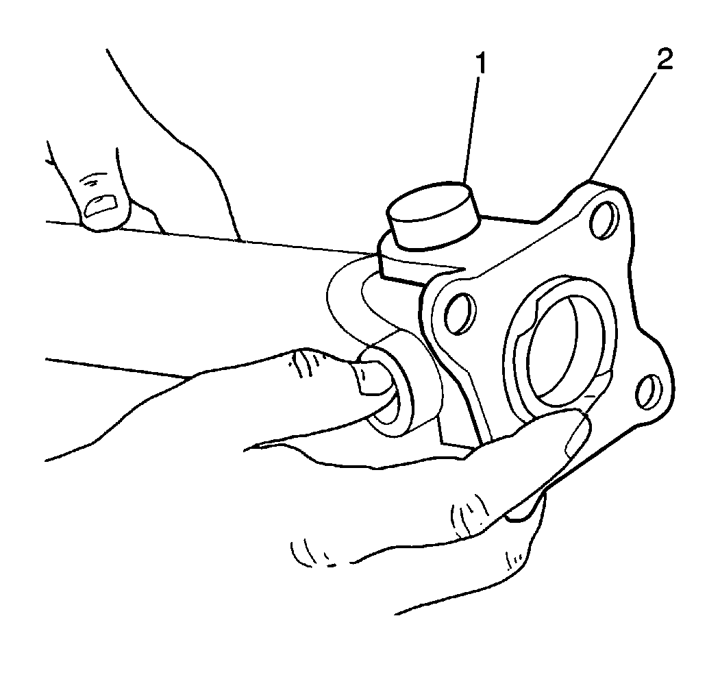
- Install the pinion flange yoke (2) onto
the spider.
- Install the bearing cap (1) into the pinion flange yoke (2). Tap gently
with a hammer in order to ensure the bearing cap fits smoothly over the spider.
- Install the opposite bearing cap into the pinion flange yoke (2). Tap
gently with a hammer until a snap ring can be fitted.
- Install 1 snap ring into the pinion flange yoke (2).
- Inspect the snap ring upon installation. Ensure the snap ring is completely
seated and firm.
- Using an 18 mm socket in conjunction with a 24 mm socket
and a soft-jaw vise, place the pinion flange yoke (2) into the soft-jaw vise with
the 18 mm socket acting as a driver and the 24 mm socket acting as
a hollow support. Tighten the vise until the opposite bearing cap is pressed into
the pinion flange yoke (2) in order that a snap ring can be fitted.
- Install 1 snap ring into the pinion flange yoke (2).
- Inspect the snap ring upon installation. Ensure the snap ring is completely
seated and firm.
- Install the propeller shaft into the vehicle. Refer to
Two-Piece Propeller Shaft Replacement
and
Rear Propeller Shaft Replacement
.


