Removal Procedure
- Remove the camshafts. Refer to Camshaft Replacement - Left Side .
- Remove the lifters. Refer to Valve Lifter Replacement - Left Side .
- Remove the exhaust manifold. Refer to Exhaust Manifold Replacement in Engine Exhaust
- Remove the water crossover pipe. Refer to Engine Coolant Crossover Pipe Replacement .
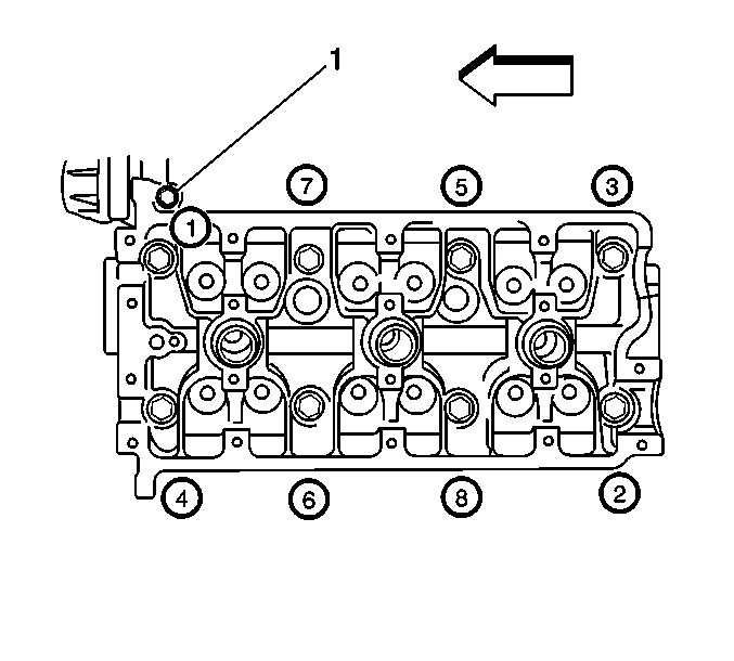
- Remove the hex bolt (1).
- Remove the cylinder head bolts in the proper order.
- Remove the cylinder heads.
- Clean the cylinder head mating surface.
- Clean the cylinder block mating surface.
- Clean the cylinder head bolt threads and bolts. Replace any stretched or damaged bolts.
- Clean the cylinder block bolt holes of all debris, threadlocker, sealant etc. Installing a bolt to a blocked bolt hole will cause incorrect torque and may cause cylinder head/block damage.

Installation Procedure
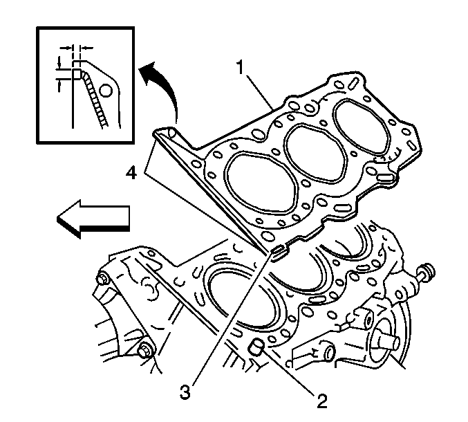
- Install the knock pin (2) to the cylinder block.
- Apply sealant (4), GM P/N 12346240 to the cylinder head gasket (1) as shown.
- Install the cylinder head gasket to the block with the 86FA mark (3) facing up.
- Install the cylinder head to the block.
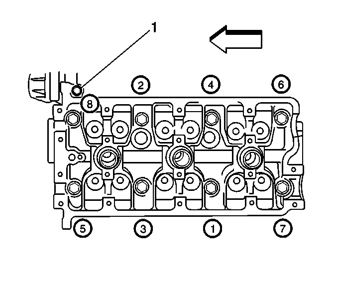
- Apply clean engine oil to the bolt threads and install the cylinder head bolts.
- Tighten the cylinder head bolts.
- Loosen the cylinder head bolts in the reverse order to 0 torque.
- Tighten the cylinder head bolts.
- Tighten the cylinder head bolts.
- Tighten the cylinder head bolts.
- Install the hex bolt (1).
- Install the water crossover pipe. Refer to Engine Coolant Crossover Pipe Replacement .
- Install the exhaust manifold. Refer to Exhaust Manifold Replacement
- Install the lifters. Refer to Valve Lifter Replacement - Left Side .
- Install the camshafts. Refer to Camshaft Replacement - Left Side .


Notice: Use the correct fastener in the correct location. Replacement fasteners must be the correct part number for that application. Fasteners requiring replacement or fasteners requiring the use of thread locking compound or sealant are identified in the service procedure. Do not use paints, lubricants, or corrosion inhibitors on fasteners or fastener joint surfaces unless specified. These coatings affect fastener torque and joint clamping force and may damage the fastener. Use the correct tightening sequence and specifications when installing fasteners in order to avoid damage to parts and systems.
Notice: In order to prevent warpage of the cylinder head, follow the sequence shown whenever removing or installing the head.
Important: The cylinder head bolts must be torqued in 2 stages, loosened, and then retorqued in 3 stages in order to ensure against compression and coolant leaks.
Tighten
Tighten the cylinder head bolts in the sequence shown to 53 N·m
(38.5 lb ft).
Tighten
Tighten the cylinder head bolts in the sequence shown to 84 N·m
(61 lb ft).
Tighten
Tighten the cylinder head bolts in the sequence shown to 53 N·m
(38.5 lb ft).
Tighten
Tighten the cylinder head bolts in the sequence shown to 84 N·m
(61 lb ft).
Tighten
Tighten the cylinder head bolts in the sequence shown to 105 N·m
(76 lb ft).
Tighten
Tighten the bolt to 11 N·m (7.5 lb ft).
