Tools Required
J 42492-A (KM-421-A) Timing Belt Adjuster
Removal Procedure
- Remove the fuel pump fuse.
- Start the engine. Crank the engine after it stalls for 10 seconds to rid the fuel system fuel pressure.
- Drain the engine coolant. Refer to Cooling System Draining and Filling .
- Disconnect the negative battery cable.
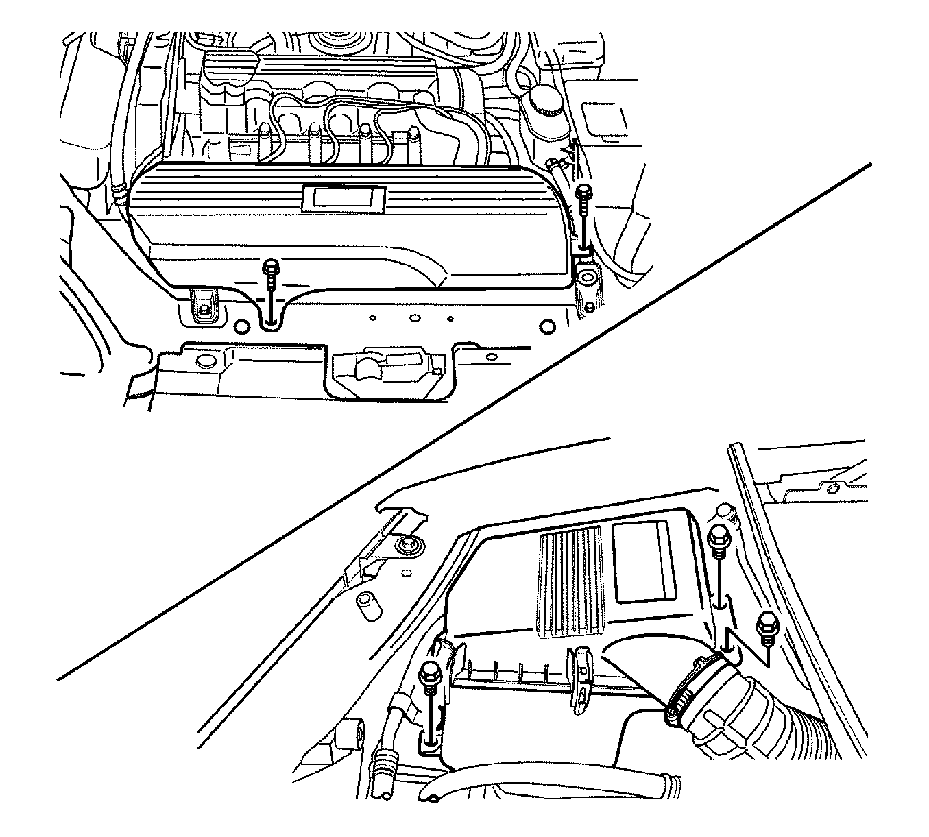
- Remove the air filter housing bolts and the air filter housing assembly.
- Remove the air inlet duct bolts and air inlet duct.
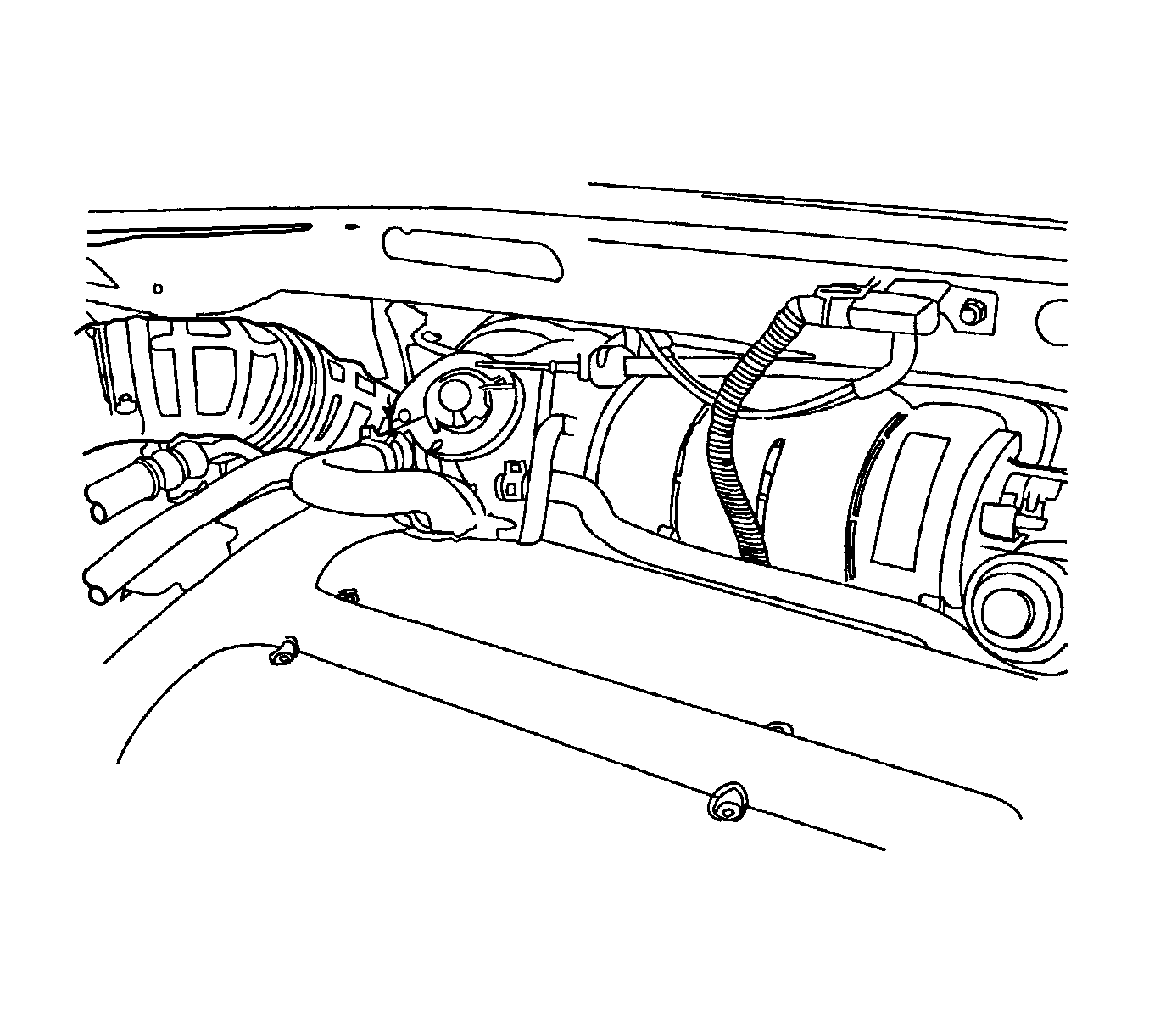
- Disconnect the intake air temperature (IAT) sensor connector.
- Disconnect the breather hose from the valve cover.
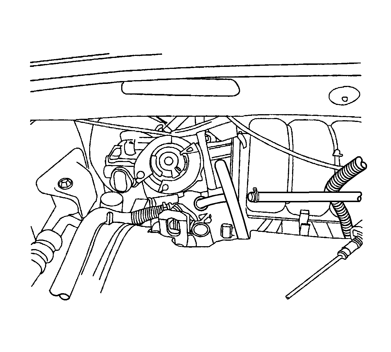
- Remove the air intake tube from the throttle body.
- Disconnect the camshaft position (CMP) sensor connector.
- Disconnect the oxygen sensor connector.
- Disconnect the engine coolant temperature (ECT) sensor connector.
- Disconnect the coolant temperature gage connector.
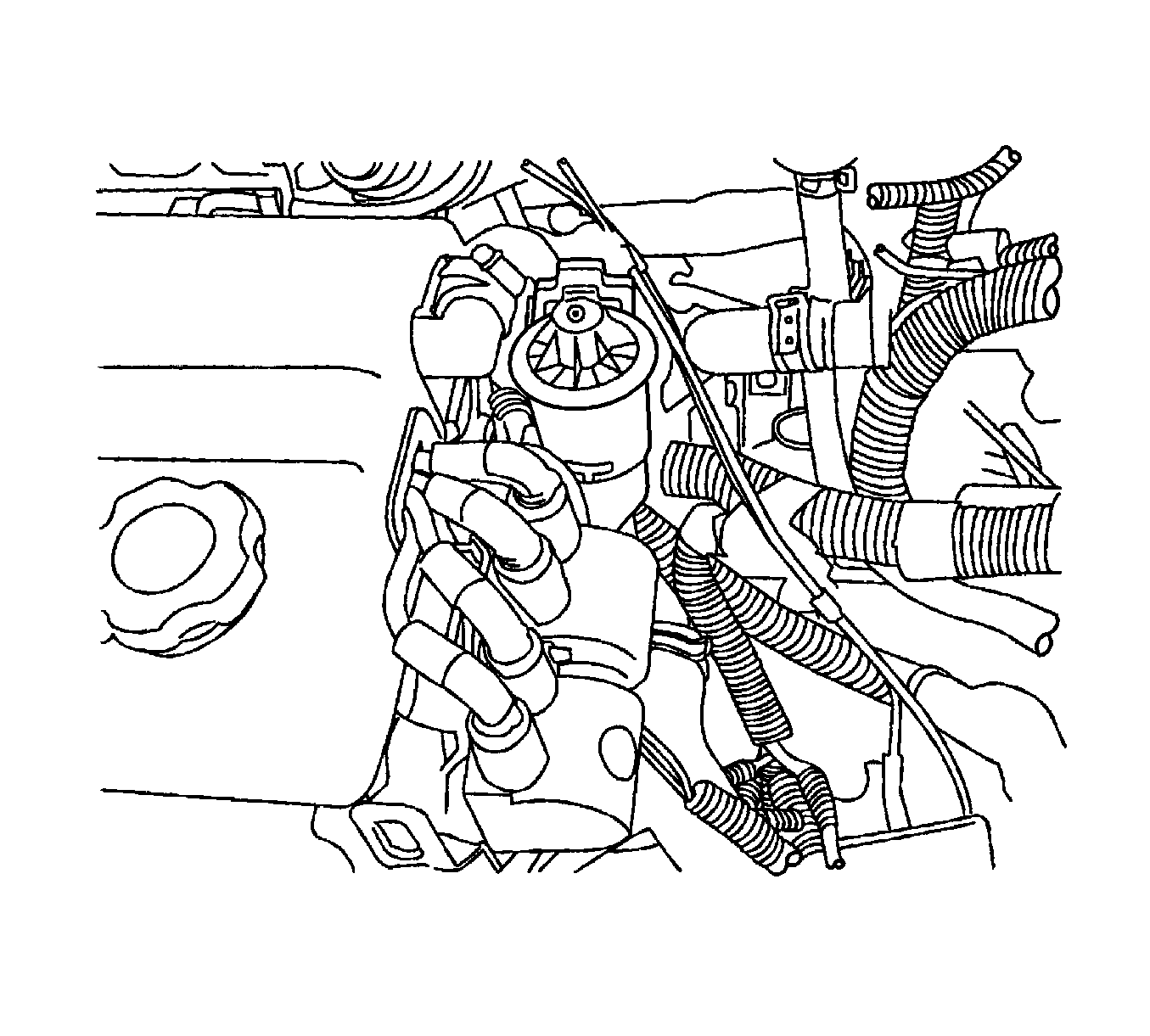
- Disconnect the EGR valve connector.
- Remove the electronic ignition (EI) system ignition coil. Refer to Ignition Coil Replacement .
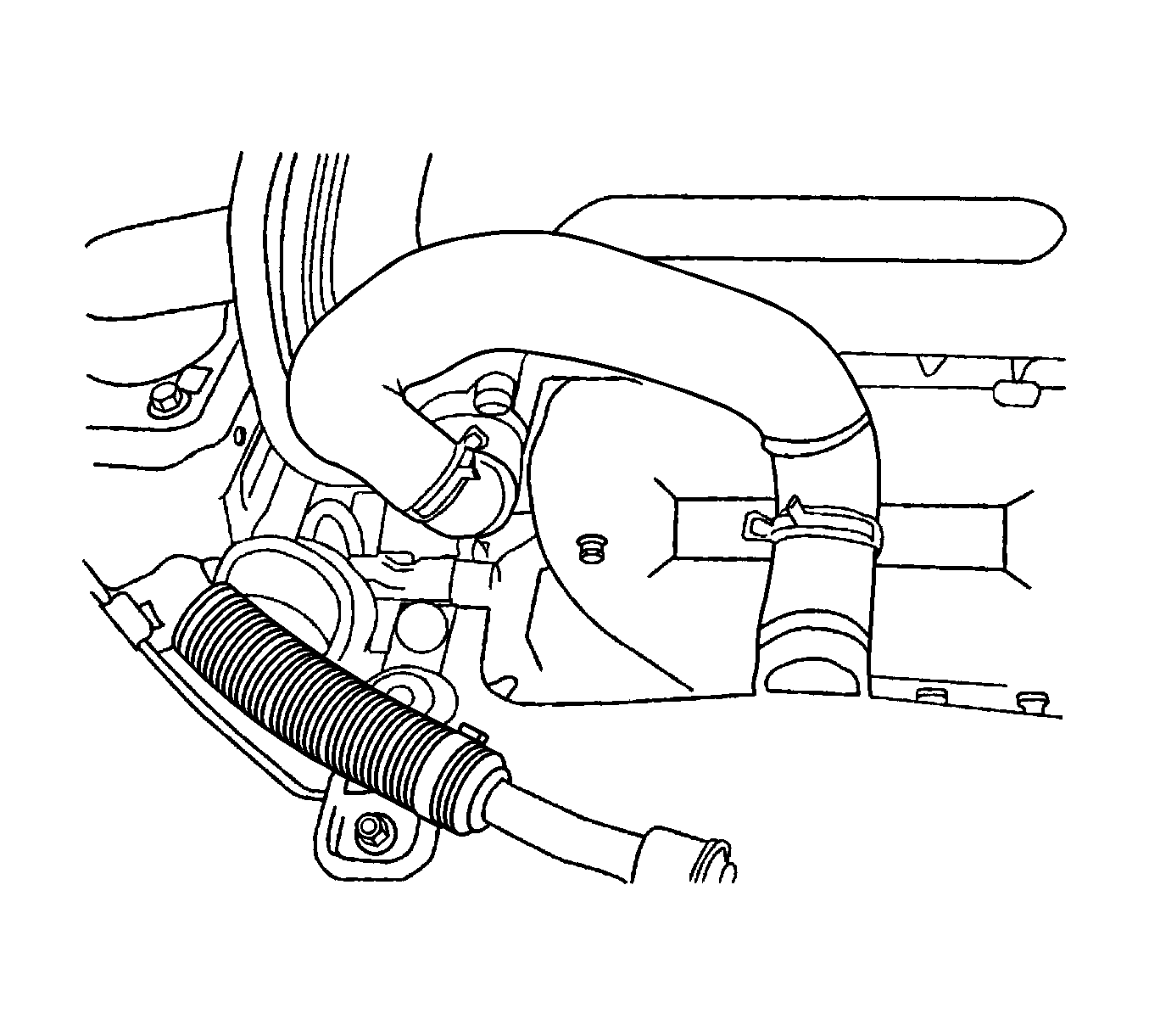
- Disconnect the coolant hose from the throttle body.
- Disconnect the coolant hose from the cylinder head.
- Disconnect the upper radiator hose at the thermostat housing.
- Remove the right front wheel. Refer to Tire and Wheel Removal and Installation .
- Remove the right front wheel well splash shield.
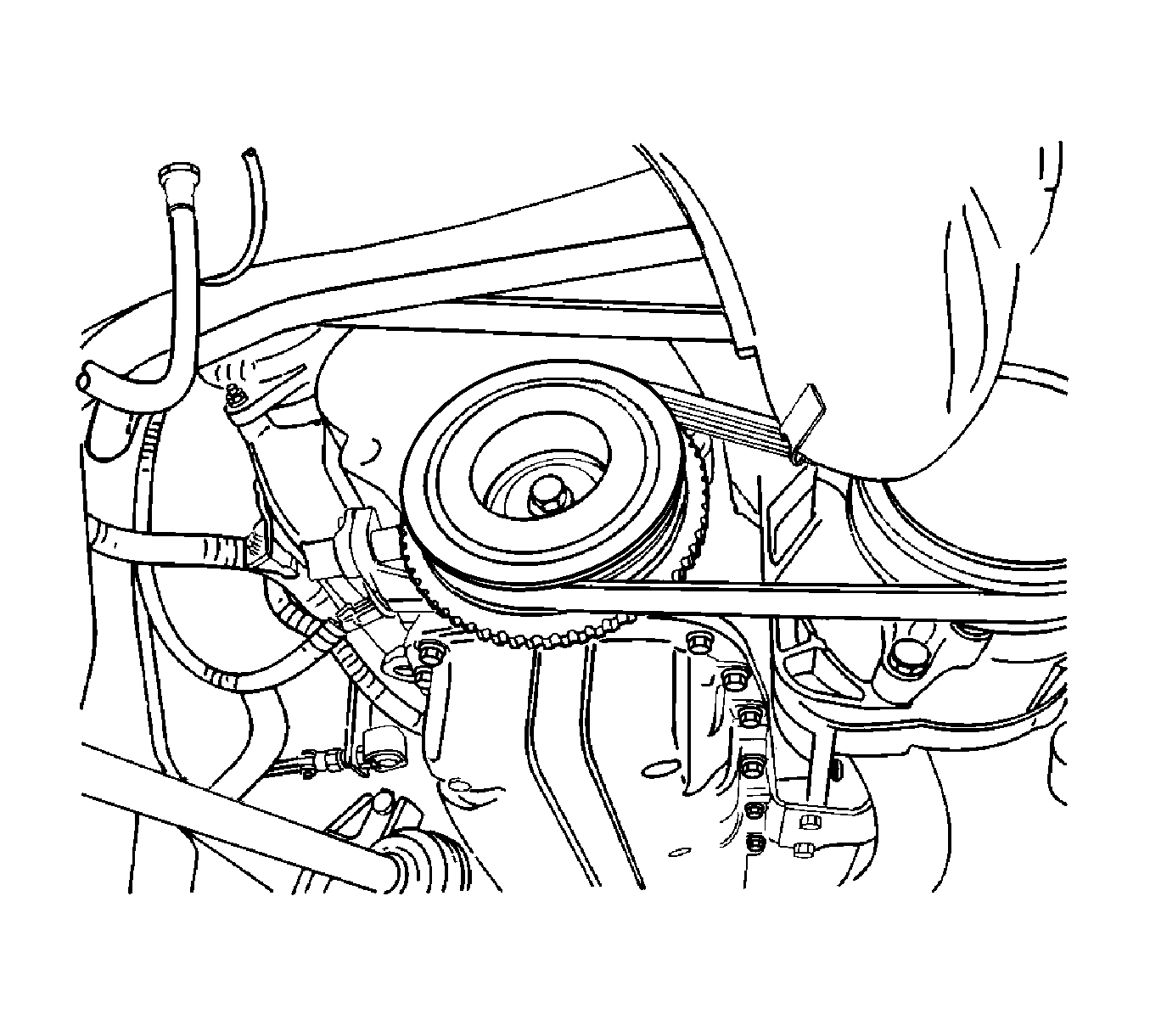
- Remove the serpentine accessory drive belt. Refer to Power Steering Pump Belt Replacement .
- Remove the crankshaft pulley bolt.
- Remove the crankshaft pulley.
- Remove the upper front timing belt cover bolts.
- Remove the upper front timing belt cover.
- Remove the lower front timing belt cover bolts.
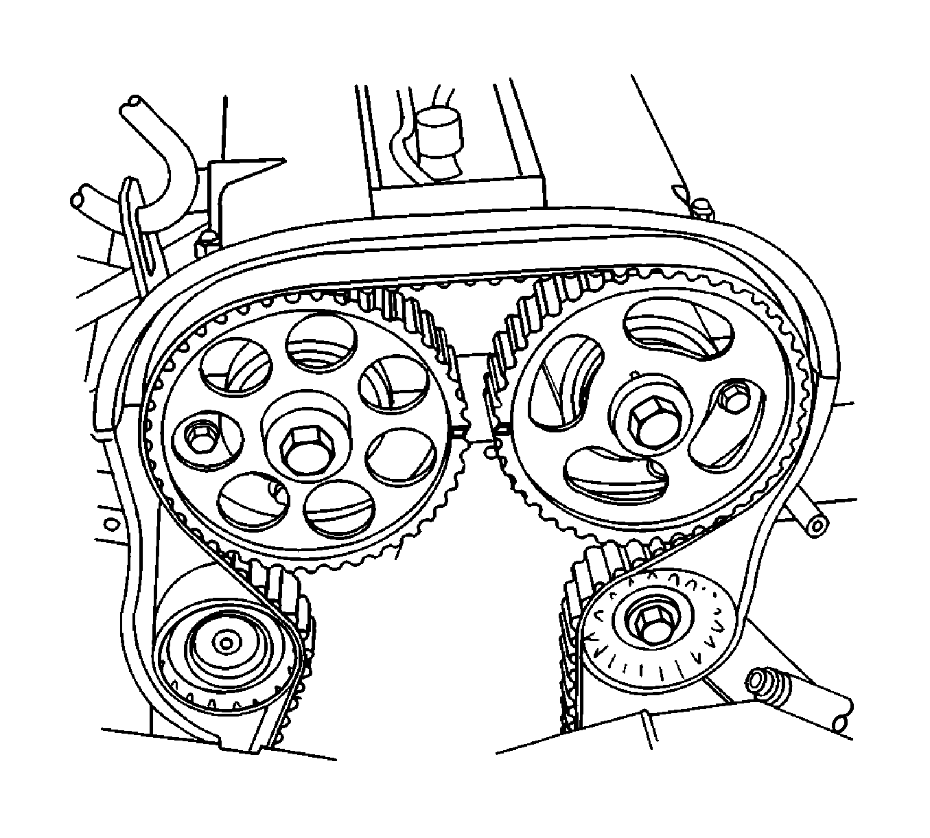
- Align the camshaft gear timing marks.
- Remove the lower front timing belt cover.
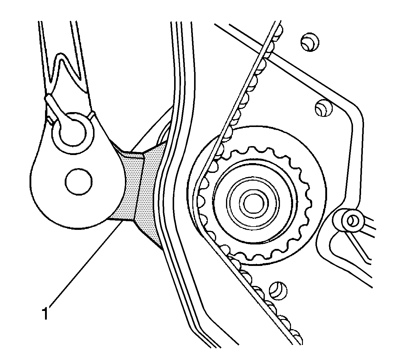
- Slightly loosen the water pump retaining bolts.
- Rotate the water pump counterclockwise using the J 42492-A (1) to relieve the timing belt tension.
- Remove the timing belt. Refer to Timing Belt Replacement .
- Disconnect the engine ventilation hose at the camshaft cover.
- Remove the oil filler cap.
- Remove the spark plug cover bolts.
- Remove the spark plug cover.
- Disconnect the ignition wires from the spark plugs.
- Remove the camshaft cover nuts.
- Remove the camshaft cover washers.
- Remove the camshaft cover and the camshaft cover gasket.
- While holding the intake camshaft firmly in place, remove the intake camshaft gear bolt.
- Remove the intake camshaft gear.
- While holding the exhaust camshaft firmly in place, remove the exhaust camshaft gear bolt.
- Remove the exhaust camshaft gear.
- Remove the timing belt automatic tensioner bolts.
- Remove the timing belt automatic tensioner.
- Remove the timing belt idler pulley bolt.
- Remove the timing belt idler pulley.
- Remove the right engine mount. Refer to Engine Mount Replacement .
- Remove the rear timing belt cover bolts.
- Remove the rear timing belt cover.
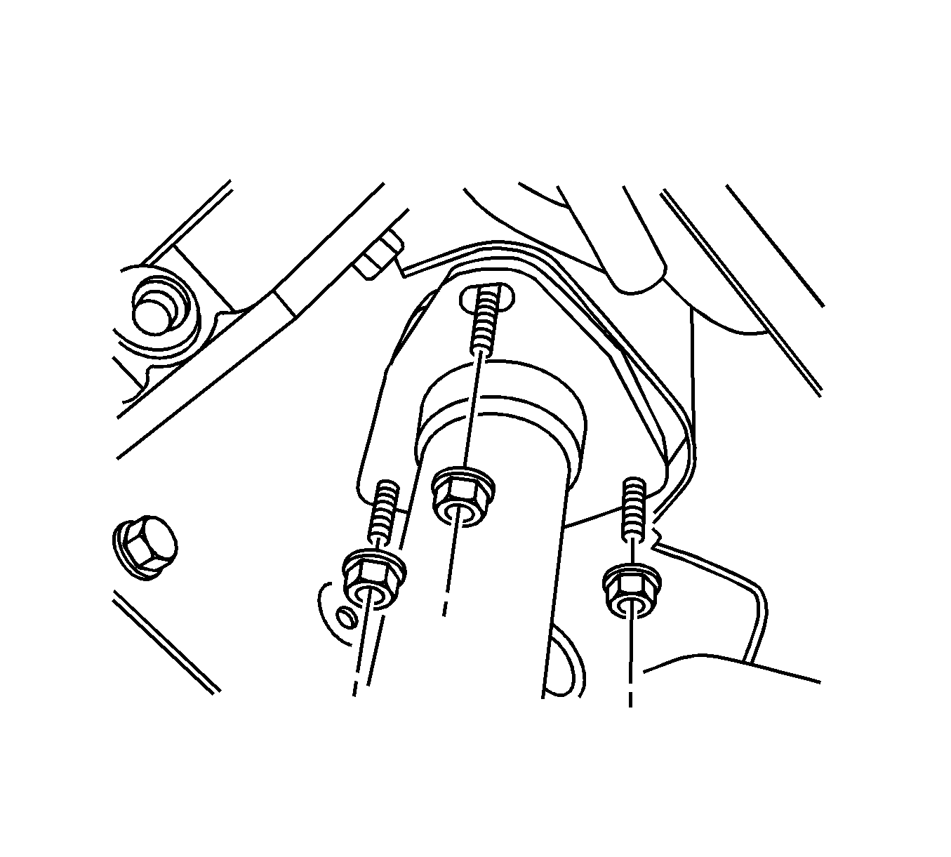
- Remove the exhaust flex pipe retaining nuts at the exhaust manifold studs.
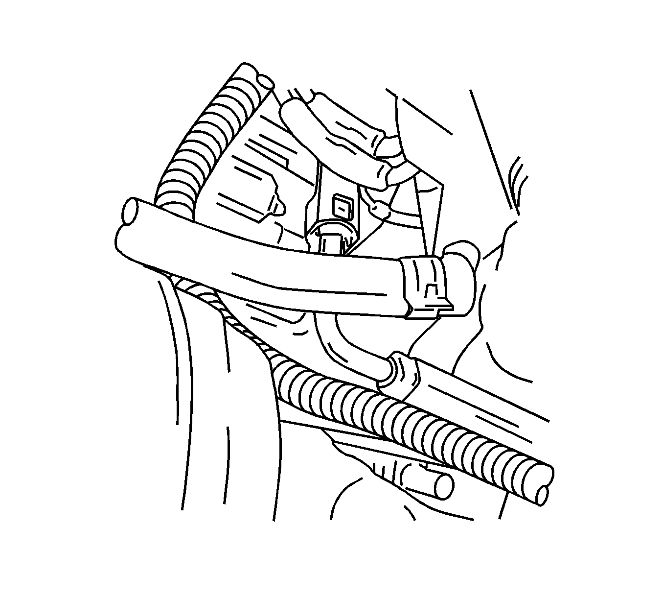
- Disconnect all of the necessary vacuum hoses and the brake booster hose at the intake manifold.
- Disconnect the fuel return line at the fuel pressure regulator.
- Disconnect the fuel feed line at the fuel rail.
- Remove the generator upper retaining bolt.
- Disconnect the heater inlet hose at the cylinder head.
- Disconnect the surge tank coolant hose at the throttle body.
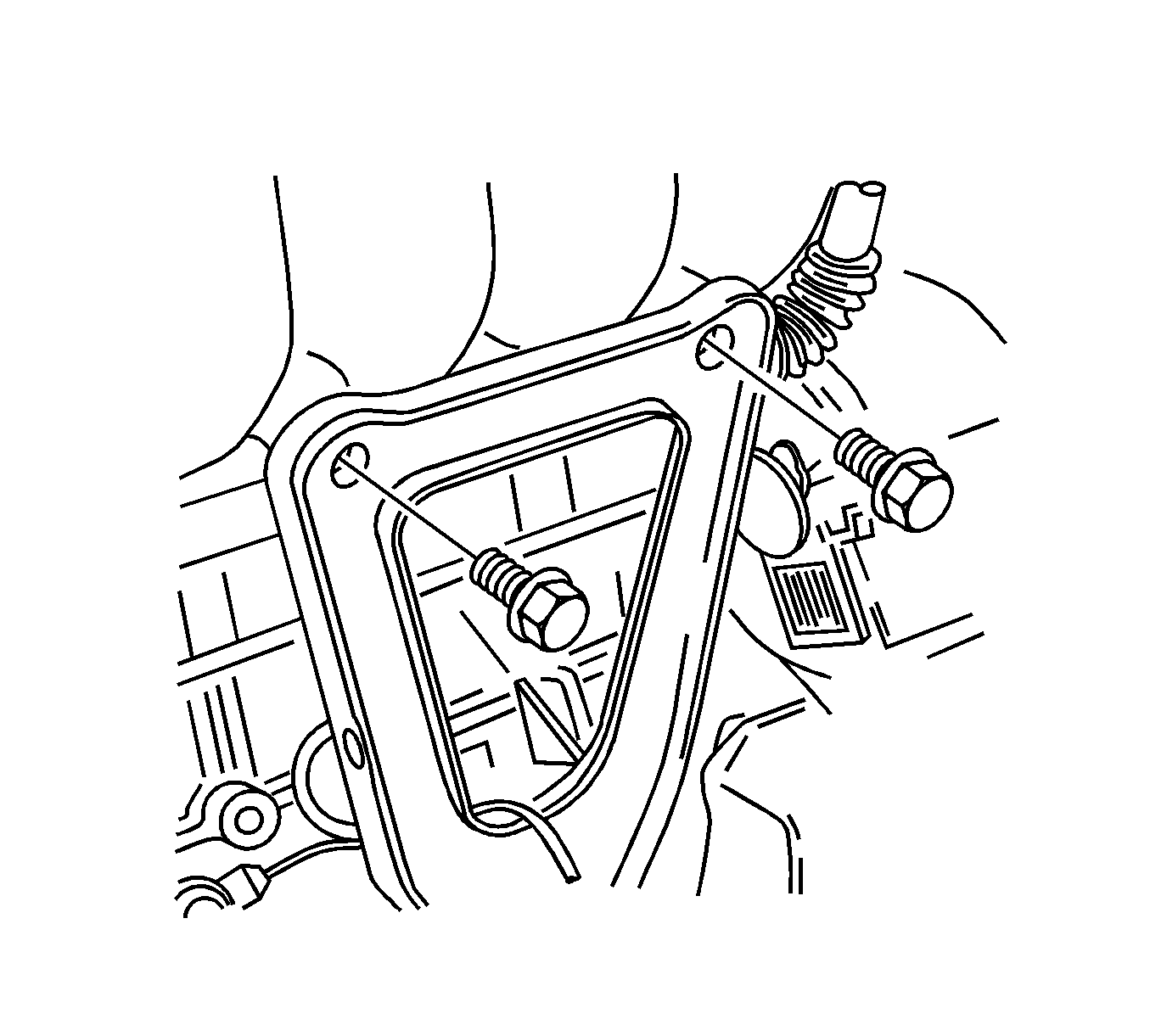
- Remove the upper intake manifold support bracket bolts at the intake manifold.
- Disconnect the throttle cable at the throttle body and the intake manifold.
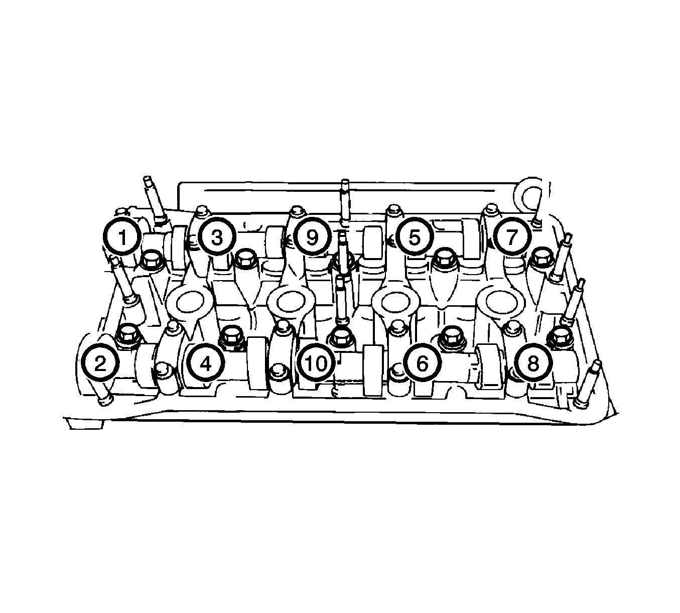
- Loosen all of the cylinder head bolts gradually and in the sequence shown.
- Remove the cylinder head bolts.
- Remove the cylinder head with the intake manifold and the exhaust manifold attached.
- Remove the cylinder head gasket.
Caution: Refer to Safety Glasses Caution in the Preface section.
Caution: Valve springs can be tightly compressed. Use care when removing the retainers and plugs. Personal injury could result.
Caution: Remove the fuel tank cap and relieve the fuel system pressure before servicing the fuel system in order to reduce the risk of personal injury. After you relieve the fuel system pressure, a small amount of fuel may be released when servicing the fuel lines, the fuel injection pump, or the connections. In order to reduce the risk of personal injury, cover the fuel system components with a shop towel before disconnection. This will catch any fuel that may leak out. Place the towel in an approved container when the disconnection is complete.
Caution: Refer to Battery Disconnect Caution in the Preface section.
Notice: Do not use belt dressing on the drive belt. Belt dressing causes the breakdown of the composition of the drive belt. Failure to follow this recommendation will damage the drive belt.
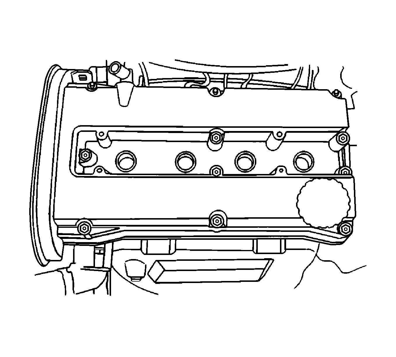
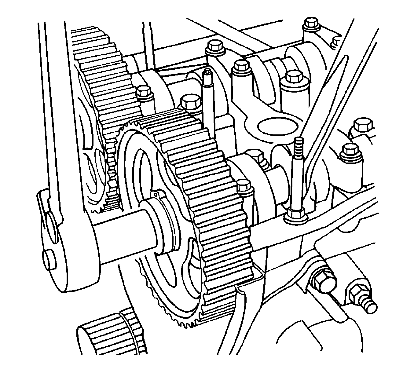
Notice: Use extreme care when removing the camshaft not to nick, scratch, or damage the camshaft lobes or bearing surfaces.
Notice: All camshaft journals are the same diameter, so care must be used in removing or installing the camshaft to avoid damage to the camshaft bearings.
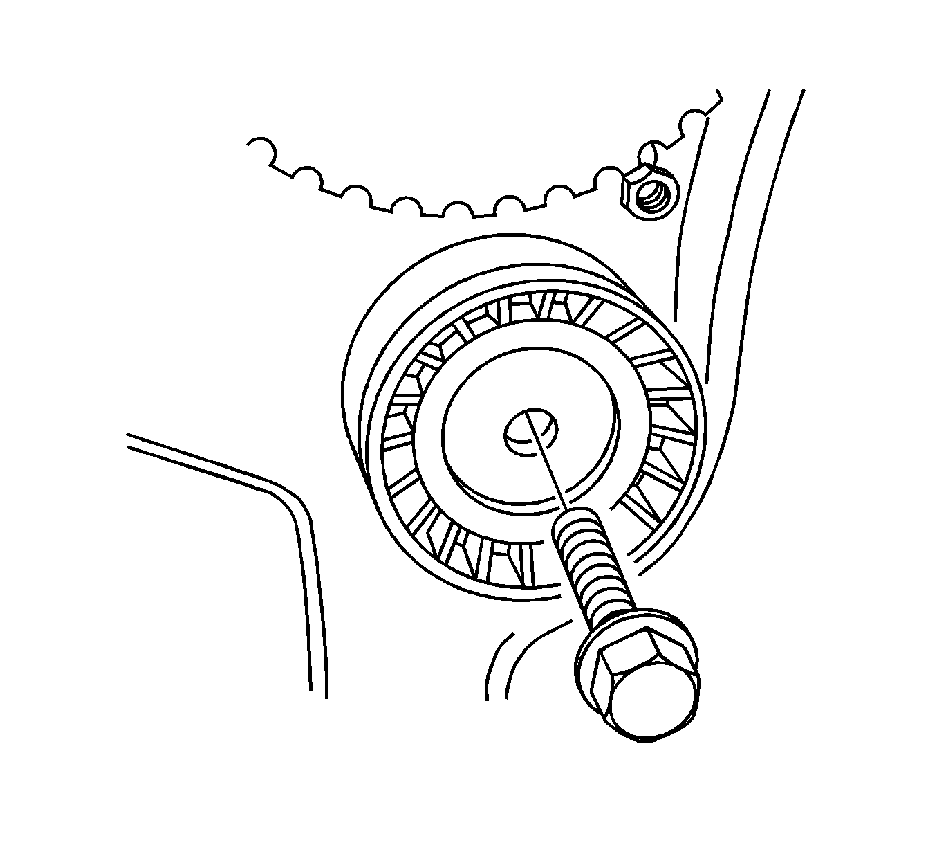
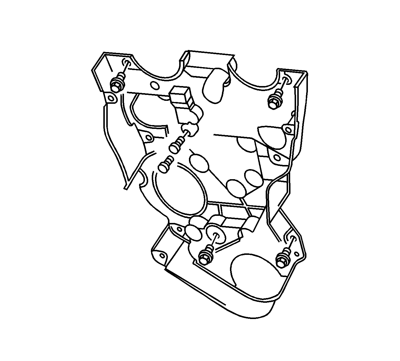
Notice: Use extreme care when removing the cylinder head to prevent any engine oil , dirt, or coolant from entering the engine. Damage to the engine could result.
Installation Procedure
- Install the cylinder head gasket.
- Install the cylinder head with the intake manifold and the exhaust manifold attached.
- Install the cylinder head bolts.
- Tighten all of the cylinder head bolts gradually and in the sequence shown.
- Connect the throttle cable at the throttle body and the intake manifold.
- Install the upper intake manifold support bracket bolts at the intake manifold.
- Connect the surge tank coolant hose at the throttle body.
- Connect the heater inlet hose at the cylinder head.
- Install the generator upper retaining bolt.
- Connect the fuel feed line at the fuel rail.
- Connect the fuel return line at the fuel pressure regulator.
- Connect all of the necessary vacuum hoses and the brake booster hose at the intake manifold.
- Install the exhaust flex pipe retaining nuts at the exhaust manifold studs.
- Install the rear timing belt cover.
- Install the rear timing belt cover bolts.
- Install the right engine mount. Refer to Engine Mount Replacement .
- Install the timing belt idler pulley.
- Install the timing belt idler pulley bolt.
- Install the timing belt automatic tensioner.
- Install the timing belt automatic tensioner bolts.
- Install the exhaust camshaft gear.
- While holding the exhaust camshaft firmly in place, install the exhaust camshaft gear bolt.
- Install the intake camshaft gear.
- While holding the intake camshaft firmly in place, install the intake camshaft gear bolt.
- Install the camshaft cover and the camshaft cover gasket.
- Install the camshaft cover washers.
- Install the camshaft cover nuts.
- Connect the ignition wires to the spark plugs.
- Install the spark plug cover.
- Install the spark plug cover bolts.
- Install the oil filler cap.
- Disconnect the engine ventilation hose at the camshaft cover.
- Install the timing belt. Refer to Timing Belt Replacement .
- Rotate the water pump clockwise using the J 42492-A (1).
- Tighten the water pump retaining bolts.
- Align the camshaft gear timing marks.
- Install the lower front timing belt cover.
- Install the lower front timing belt cover bolts.
- Install the upper front timing belt cover.
- Install the upper front timing belt cover bolts.
- Install the crankshaft pulley.
- Install the crankshaft pulley bolt.
- Install the serpentine accessory drive belt. Refer to Power Steering Pump Belt Replacement .
- Install the right front wheel well splash shield.
- Install the right front wheel. Refer to Tire and Wheel Removal and Installation .
- Connect the upper radiator hose at the thermostat housing.
- Connect the coolant hose from the cylinder head.
- Connect the coolant hose from the throttle body.
- Install the electronic ignition (EI) system ignition coil. Refer to Ignition Coil Replacement .
- Connect the EGR valve connector.
- Connect the coolant temperature gage connector.
- Connect the engine coolant temperature (ECT) sensor connector.
- Connect the oxygen sensor connector.
- Connect the camshaft position (CMP) sensor connector.
- Install the air intake tube from the throttle body.
- Connector the breather hose from the valve cover.
- Connect the intake air temperature (IAT) sensor connector.
- Install the air inlet duct bolts and air inlet duct.
- Install the air filter housing bolts and the air filter housing assembly.
- Connect the negative battery cable.
- Fill the engine coolant. Refer to Cooling System Draining and Filling .
- Install the fuel pump fuse.
- Start the engine and inspect for leaks.

Notice: Refer to Fastener Notice in the Preface section.
Tighten
Tighten the cylinder head bolts to 25 N·m (18 lb ft) +70°+70°+50°.

Tighten
Tighten the bracket bolts to 25 N·m (18 lb ft).

Tighten
Tighten the generator upper bolt to 20 N·m (15 lb ft).


Tighten
Tighten the cover bolts to 10 N·m (89 lb in).

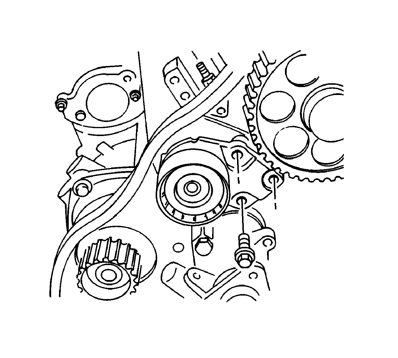
Tighten
Tighten the tensioner bolts to 25 N·m (18 lb ft).

Notice: Use extreme care when removing the camshaft not to nick, scratch, or damage the camshaft lobes or bearing surfaces.
Notice: All camshaft journals are the same diameter, so care must be used in removing or installing the camshaft to avoid damage to the camshaft bearings.
Tighten
Tighten the exhaust gear bolt to 67.5 N·m (49 lb ft).
Tighten
Tighten the intake gear bolt to 67.5 N·m (49 lb ft).

Tighten
Tighten the cover nuts to 10 N·m (89 lb in).
Tighten
Tighten the cover bolts to 3 N·m (27 lb in).

Tighten
Tighten the water pump bolt to 10 N·m (89 lb in).

Tighten
Tighten the cover bolts to 10 N·m (89 lb in).
Tighten
Tighten the cover bolts to 10 N·m (89 lb in).

Notice: Do not use belt dressing on the drive belt. Belt dressing causes the breakdown of the composition of the drive belt. Failure to follow this recommendation will damage the drive belt.


Tighten
Tighten the air duct and inlet bolts to 8 N·m (71 lb in).
