For 1990-2009 cars only
Exhaust Manifold Heat Shield Replacement LLV
Removal Procedure
Warning: Refer to Exhaust Service Warning in the Preface section.
Warning: Refer to Protective Goggles and Glove Warning in the Preface section.
- Remove the air cleaner outlet duct. Refer to Air Cleaner Outlet Duct Replacement.
- Remove the air cleaner assembly. Refer to Air Cleaner Assembly Replacement.
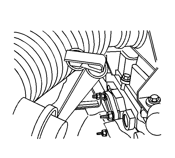
- If equipped with M30, remove the transmission filler tube bracket nut from the A.I.R. adapter, and position aside.
- Remove the heated oxygen sensor (HO2S) from the exhaust manifold. Refer to Heated Oxygen Sensor 1 Replacement.
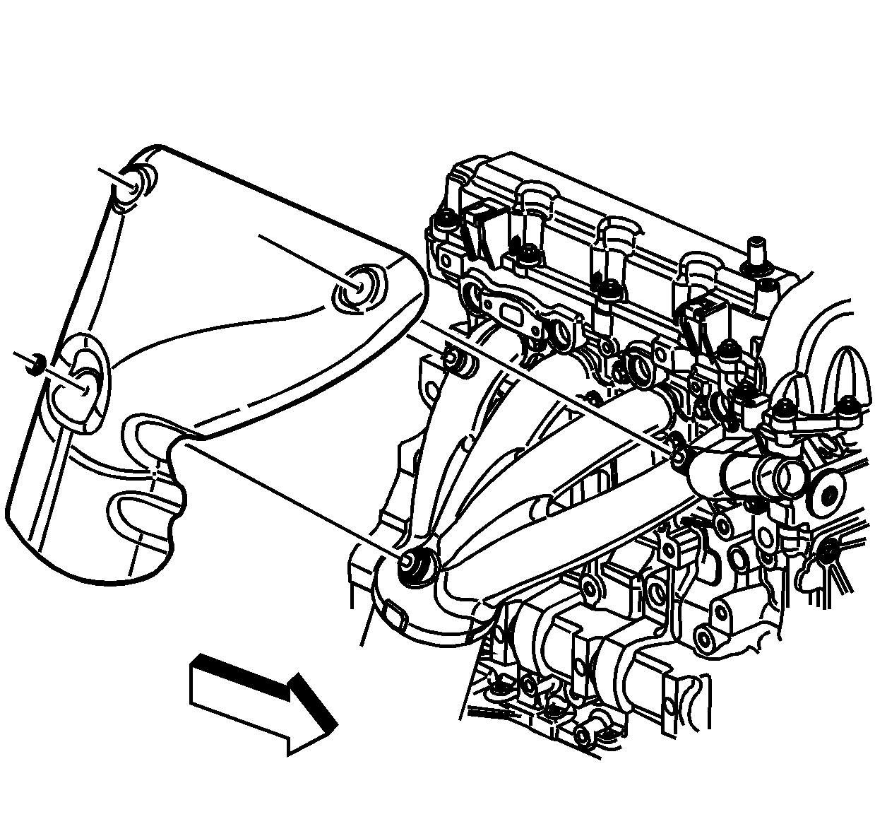
- Remove the 3 nuts securing the heat shield to the exhaust manifold.
- Remove the exhaust manifold heat shield from the exhaust manifold.


Installation Procedure
- Position the exhaust manifold heat shield to the exhaust manifold.
- Apply anti-seize GM P/N 12371386 (Canadian P/N 993128) to the exhaust manifold heat shield nuts.
- Install the exhaust manifold heat shield nuts and tighten to 10 N·m (89 lb in).
- Install the HO2S to the exhaust manifold. Refer to Heated Oxygen Sensor 1 Replacement.
- Position the transmission filler tube to the A.I.R. adapter if previously removed.
- Install the transmission filler tube bracket nut and tighten to 12.5 N·m (111 lb in).
- Install the air cleaner assembly. Refer to Air Cleaner Assembly Replacement.
- Install the air cleaner outlet duct. Refer to Air Cleaner Outlet Duct Replacement.

Caution: Refer to Fastener Caution in the Preface section.

Exhaust Manifold Heat Shield Replacement LLR
Removal Procedure
Warning: Refer to Exhaust Service Warning in the Preface section.
Warning: Refer to Protective Goggles and Glove Warning in the Preface section.
- Remove the air cleaner outlet duct. Refer to Air Cleaner Outlet Duct Replacement.
- Remove the air cleaner assembly. Refer to Air Cleaner Assembly Replacement.
- If equipped with M30, remove the transmission filler tube bracket nut from the A.I.R. adapter, and position aside.
- Remove the heated oxygen sensor (HO2S) from the exhaust manifold. Refer to Heated Oxygen Sensor 1 Replacement.
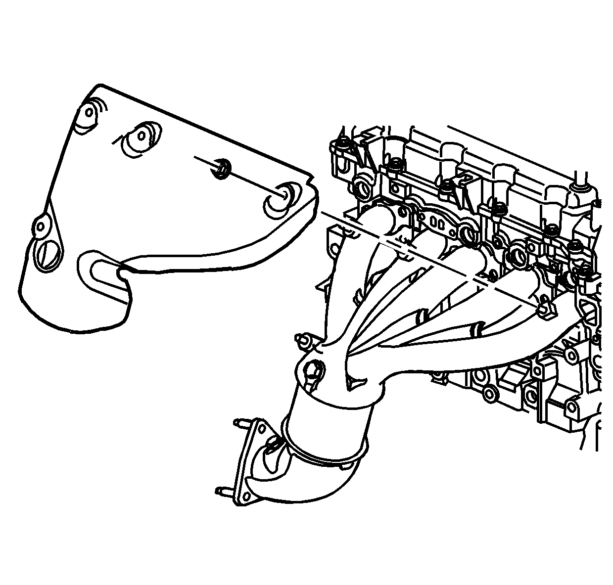
- Remove the 4 nuts securing the heat shield to the exhaust manifold.
- Remove the exhaust manifold heat shield from the exhaust manifold.


Installation Procedure
- Position the exhaust manifold heat shield to the exhaust manifold.
- Apply anti-seize GM P/N 12371386 (Canadian P/N 993128) to the exhaust manifold heat shield nuts.
- Install the exhaust manifold heat shield nuts and tighten to 10 N·m (89 lb in).
- Install the HO2S to the exhaust manifold. Refer to Heated Oxygen Sensor 1 Replacement.
- Position the transmission filler tube to the A.I.R. adapter if previously removed.
- Install the transmission filler tube bracket nut and tighten to 12.5 N·m (111 lb in).
- Install the air cleaner assembly. Refer to Air Cleaner Assembly Replacement.
- Install the air cleaner outlet duct. Refer to Air Cleaner Outlet Duct Replacement.

Caution: Refer to Fastener Caution in the Preface section.

