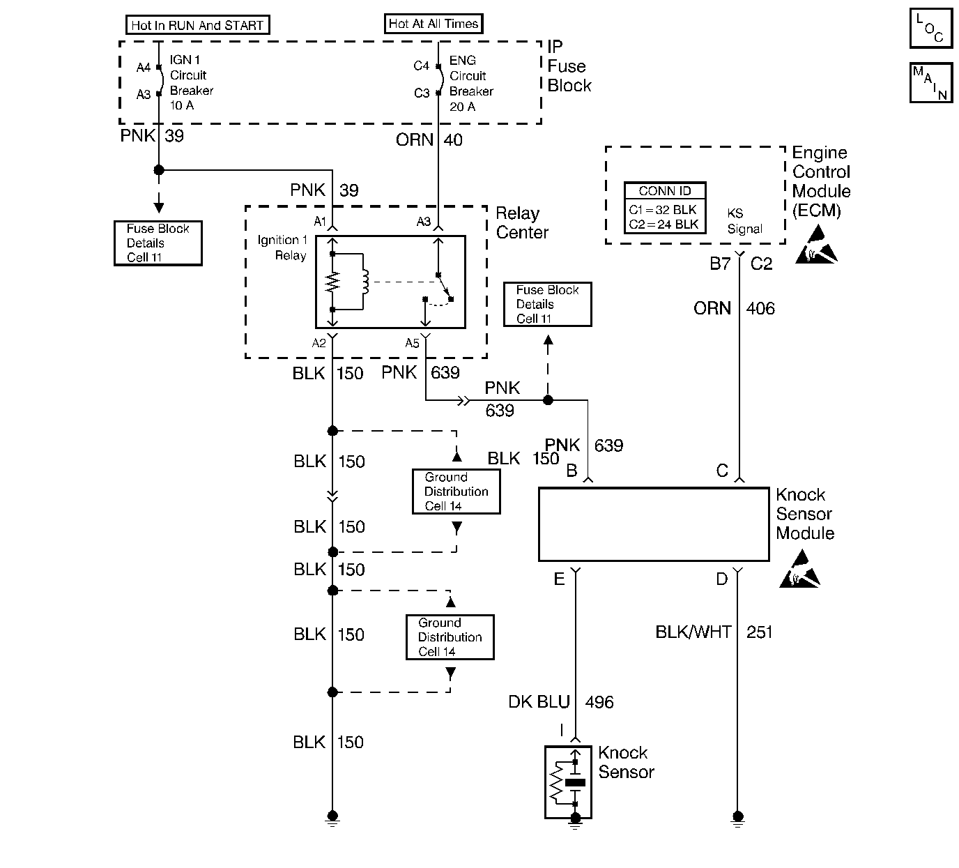
Circuit Description
The Knock Sensor (KS) system consists of a module that sends a voltage signal to the ECM. As the knock sensor detects an engine knock, the voltage from the KS module to the ECM is shuts OFF, and this signals the ECM to retard timing, if engine speed is over about 900 RPM.
Diagnostic Aids
The scan tools have two positions to diagnose the KS system. The scan tool can monitor the knock signal in order to see if the knock sensor detects a knock condition. If the KS module is functioning, the knock signal should display Yes whenever a detonation is present. The knock retard position on the scan displays the amount of ECM Commanded spark retard. The ECM can retard the timing up to 20 degrees.
If the KS system checks OK but detonation is the complaint, refer to Detonation/Spark Knock .
Use this check after you have checked the other causes of the spark knock such as the engine timing, the EGR systems, the engine temperature, or excessive engine noise.
Test Description
The numbers below refer to the step numbers on the Diagnostic Table.
-
If a DTC 43 is not set but a knock signal is indicated while running at 1500 RPM, listen for an internal engine noise. Under a no load condition there should not be any detonation. If a knock is indicated, an internal engine problem may exist.
-
This tests whether the knock signal is due to the sensor, a basic engine problem, or the KS module.
-
Usually tapping on the right exhaust manifold can generate a knock signal. You can also perform this test at idle. The test in step 2 was run at 1500 RPM in order to determine if a constant knock signal was present which would affect the engine performance.
-
If the ground circuit is faulty, the KS module will not function correctly. The test lamp should illuminate indicating the ground circuit is OK.
-
Contacting the knock sensor circuit, with a test lamp to 12 volts, should generate a knock signal in order to determine whether the knock sensor is faulty or the KS module cannot recognize a knock signal.
Step | Action | Value(s) | Yes | No |
|---|---|---|---|---|
1 | Did you perform the On-Board Diagnostic (OBD) System Check? | -- | ||
Install a scan tool. Is DTC 43 present? | -- | |||
3 |
Does the scan tool indicate a knock signal? | 1500 RPM | ||
Does the scan tool indicate a knock signal? | -- | |||
5 | Check the routing of the wire from the Knock Sensor to the KS Module. Is the wire picking up false signals from adjacent wires? | -- | ||
6 | Reroute the wire as necessary. Is the action complete? | -- | -- | |
7 | Does the engine have an internal knock? | -- | Go to Engine Mechanical | |
Does the scan tool indicate a knock signal while tapping on the engine? | 1500 RPM | Refer to Diagnostic Aids | ||
Is the test lamp ON? | -- | |||
10 | Repair the open in the ground circuit. Is the action complete? | -- | -- | |
Does the scan tool indicate a knock signal? | -- | |||
12 |
Did you find a problem? | -- | ||
13 | Replace the Knock Sensor. Is the action complete? | -- | -- | |
14 |
Did you find a problem? | -- | ||
15 |
Did you find a problem? | -- | ||
16 | Replace the KS Module. Is the action complete? | -- | -- | |
17 | Operate the vehicle within the conditions of the original symptom. Does the system now operate properly? | -- | System OK | Refer to Diagnostic Aids |
