Drive Pinion Yoke Replacement Input Shaft
Removal Procedure
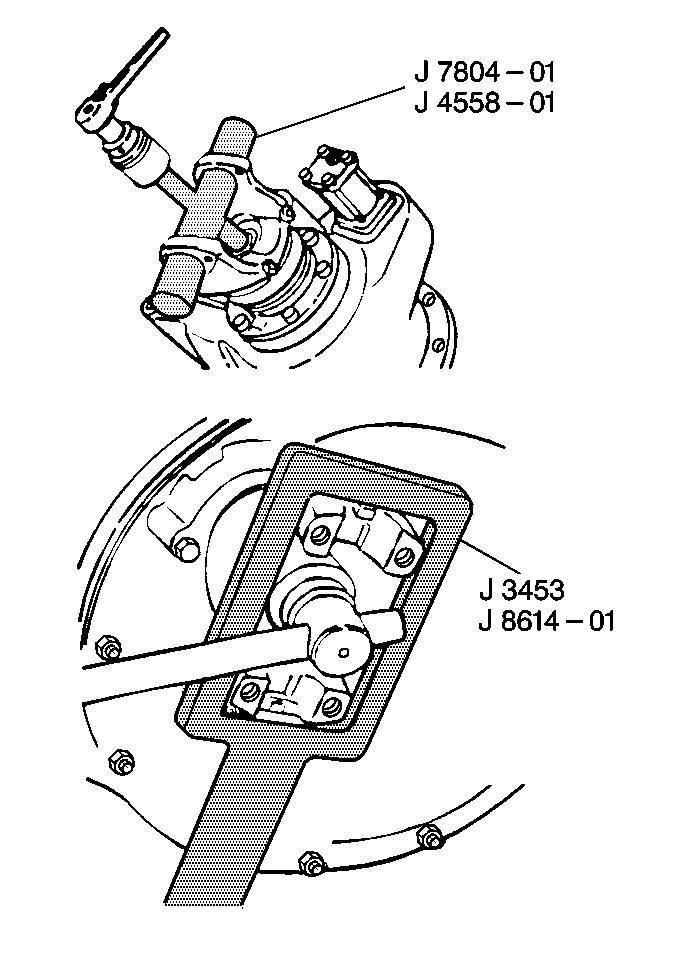
Tools Required
| • | J 7804-A Puller or |
| • | J 4558-01 Puller |
| • | J 3453 Holding Bar or |
| • | J 8614-01 Holding Bar |
- Apply the parking brake.
- Block the wheels.
- Remove the rear axle rear unit propeller shaft. Refer to appropriate procedure:
- Remove the inter-axle differential input shaft nut and the washer, if equipped.
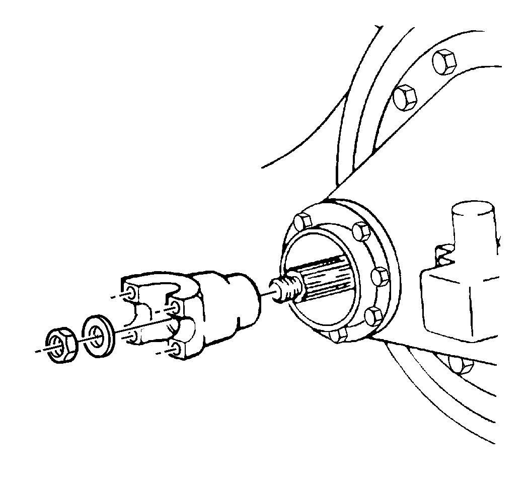
- Remove the inter-axle differential input shaft yoke.
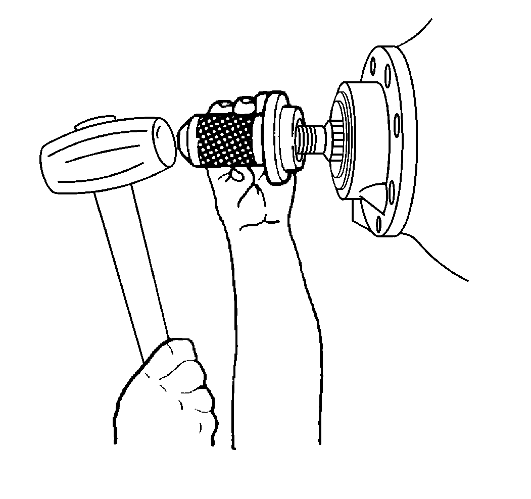
- Remove the inter-axle differential input shaft seal.
- Inspect the inter-axle differential input shaft seal surface for damage or scoring. If the seal surface is damaged, replace the inter-axle differential input shaft yoke.

Installation Procedure
- Apply Silicone Sealer (RTV) GM P/N 1052366 or equivalent to OD of the inter-axle differential input shaft seal.
- Install the inter-axle differential input shaft seal.
- Install the inter-axle differential input shaft yoke.
- Install the washer and the new inter-axle differential input shaft nut.
- If a new inter-axle differential input shaft nut with pre-applied threadlocker is unavailable, the original inter-axle differential input shaft nut may be reused under the following conditions:
- Install the rear axle rear unit propeller shaft. Refer to appropriate procedure:
- Remove the wheel blocks.
Important: Lubricate the new inter-axle differential input shaft seal lip with the rear axle lubricant. For rear axle lubricant specifications, refer to Fluid and Lubricant Recommendations .
The silicone sealer will overcome minor faults in the differential carrier seal bore.


Notice: Use the correct fastener in the correct location. Replacement fasteners must be the correct part number for that application. Fasteners requiring replacement or fasteners requiring the use of thread locking compound or sealant are identified in the service procedure. Do not use paints, lubricants, or corrosion inhibitors on fasteners or fastener joint surfaces unless specified. These coatings affect fastener torque and joint clamping force and may damage the fastener. Use the correct tightening sequence and specifications when installing fasteners in order to avoid damage to parts and systems.
Important:
• Ensure that the threads are clean and free of grease. • Apply 272 Threadlocker GM P/N 12345493 or equivalent
to the threads of the inter-axle differential input shaft nut.
Tighten
Tighten the inter-axle differential input shaft nut to
867 N·m (639 lb ft).
| • | The nut is in good condition. |
| • | The threadlocker is applied. |
Drive Pinion Yoke Replacement Output Shaft
Removal Procedure
Tools Required
| • | J 7804-A Puller |
| • | J 4558-01 Puller |
- Apply the parking brake.
- Block the wheels.
- Remove the propeller shaft. Refer to the following procedures:
- Remove the inter-axle differential output shaft nut and washer, if equipped.
- Remove the inter-axle differential output shaft yoke.
- Remove the inter-axle differential output shaft seal.
- Inspect the inter-axle differential output shaft yoke seal surface for damage or scoring. If the seal surface is damaged, replace the rear propeller shaft yoke.

Installation Procedure
- Apply Silicone Sealer (RTV) GM P/N 1052366 or equivalent to OD of the inter-axle differential output shaft seal.
- Install the inter-axle differential output shaft seal.
- Install the inter-axle differential output shaft yoke.
- Install the washer and the new inter-axle differential output shaft nut.
- Install the propeller shaft. Refer to the following procedures:
- Remove the wheel blocks.
Important: Lubricate the new inter-axle differential output shaft seal lip with the rear axle lubricant. For rear axle lubricant specifications, refer to Fluid and Lubricant Recommendations in General Information.
The silicone sealer will overcome minor faults in the differential carrier seal bore.


Notice: Use the correct fastener in the correct location. Replacement fasteners must be the correct part number for that application. Fasteners requiring replacement or fasteners requiring the use of thread locking compound or sealant are identified in the service procedure. Do not use paints, lubricants, or corrosion inhibitors on fasteners or fastener joint surfaces unless specified. These coatings affect fastener torque and joint clamping force and may damage the fastener. Use the correct tightening sequence and specifications when installing fasteners in order to avoid damage to parts and systems.
Important:
• Ensure that the threads are clean and free of grease. • Apply 272 Threadlocker GM P/N 12345493 or equivalent
to the threads of the inter-axle differential input shaft nut.
Tighten
Tighten the inter-axle differential input shaft nut to the torque listed
in
Fastener Tightening Specifications
.
If a new inter-axle differential output shaft nut with pre-applied threadlocker is unavailable, the original inter-axle differential output shaft nut may be reused under the following conditions:
| • | The nut is in good condition. |
| • | The threadlocker is applied. |
Drive Pinion Yoke Replacement Eaton and Dana/Spicer
Removal Procedure
Tools Required
| • | J 7804-A |
- Apply the parking brake.
- Block the wheels.
- Remove the propeller shaft. Refer to the following procedures:
- Remove the differential drive pinion gear nut and the washer, if equipped.
- Remove the rear propeller shaft yoke.
- Remove the differential drive pinion gear seal.
- Inspect the rear propeller shaft yoke seal surface for damage or scoring. If the seal surface is damaged, replace the rear propeller shaft yoke.

Installation Procedure
- Apply Silicone Sealer (RTV) GM P/N 1052366 or equivalent to OD of the inter-axle differential input shaft seal.
- Install the differential drive pinion gear seal.
- Install the rear propeller shaft yoke.
- Apply 272 Threadlocker GM P/N 12345493 or equivalent to the threads of the inter-axle differential drive pinion gear nut.
- Install the washer and the new inter-axle differential input shaft nut.
- Tighten the differential drive pinion gear nut to the torque specifications listed in Fastener Tightening Specifications
- Remove the wheel blocks.
- Install the propeller shaft. Refer to the following procedures:
- Remove the wheel blocks.
Important: Lubricate the new differential drive pinion seal lip with the rear axle lubricant. For rear axle lubricant specifications, refer to Fluid and Lubricant Recommendations
The silicone sealer will overcome minor faults in the differential carrier seal bore.


Important: Ensure that the threads are clean and free of grease.
If a new inter-axle differential input shaft nut with pre-applied threadlocker is unavailable, reuse the original inter-axle differential input shaft nut under the following conditions:
| • | The nut is in good condition. |
| • | The threadlocker is applied. |
