Power Steering Pump Replacement Saginaw with Integral Reservoir
Removal Procedure
Tools Required
J 42971 Quick Disconnect
Tool
Important: Always clean the connectors and lubricate the tool end in power steering
fluid when inserting into the coupling.
Important: Check all power steering system quick connect connections by trying
to pull the hose assembly out of the fitting using a firm hand tug. Repeat
the step if the connector is pulled out of the male fitting. If the problem
persists, inspect and replace the hose assembly if the quick connect
is damaged.
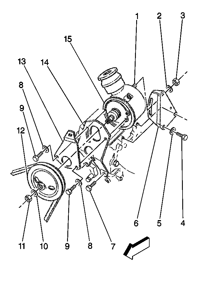
- Disconnect the power steering
hoses at the pump (15).
- Cap the hoses in order to prevent dirt from entering the system.
- Tag the hose locations.
- Use the following steps in order to remove the drive belt:
| 4.1. | Loosen the two front bolts (9) and the rear nut (3). |
| 4.2. | Move the pump inboard. |
| 4.3. | Remove the drive belt. Refer toDrive Belt Replacement
. |
- Remove the nut (11) and the washer (10).
Notice: Do not hammer the pulley off the shaft. The pulley or the pump
may be damaged.
- Use a suitable puller in order to remove the pulley (12).
- Remove the nut (3) and the washer (2).
- Remove the bolts (4) and the washers (5).
- Remove the rear bracket (6).
- Remove the following components:
- Remove the front adjustment bracket (13).
- Remove the pump (15).
Installation Procedure

- Install the pump (15)
to the front bracket (14).
- Install the front adjustment bracket (13).
- Install the following components to the pump (15):
Notice: Use the correct fastener in the correct location. Replacement fasteners
must be the correct part number for that application. Fasteners requiring
replacement or fasteners requiring the use of thread locking compound or sealant
are identified in the service procedure. Do not use paints, lubricants, or
corrosion inhibitors on fasteners or fastener joint surfaces unless specified.
These coatings affect fastener torque and joint clamping force and may damage
the fastener. Use the correct tightening sequence and specifications when
installing fasteners in order to avoid damage to parts and systems.
- Install the rear
bracket (6) to the engine.
- Install the following components:
Tighten
Tighten the rear bracket bolts to 37 N·m (27 lb ft).
- Install the following components:
Notice: Do not hammer the pulley onto the shaft. The pulley or the pump
may be damaged.
- Use a suitable pulley installer in order to install the pulley (12).
- Install the washer (10).
- Install the nut (11).
Tighten
Tighten the pulley nut to 64 N·m (47 lb ft).
- Install the drive belt. Refer toDrive Belt
Replacement
.
- Tighten the pump mounting bolts (9).
Tighten
Tighten the pump mounting bolts to 37 N·m (27 lb ft).
- Tighten the pump mounting nut (3).
Tighten
Tighten the pump mounting nut to 26 N·m (19 lb ft).
- Connect the hoses.
- Refill the power steering reservoir. Refer to
Fluid and Lubricant Recommendations
.
- Bleed the power steering system. Refer to
Power Steering System Bleeding
.
Power Steering Pump Replacement Saginaw with Remote Reservoir
Removal Procedure
Tools Required
J 42971 Quick Disconnect
Tool
Important: Always clean the connectors and lubricate the tool end in power steering
fluid when inserting into the coupling.
Important: Check all power steering system quick connect connections by trying
to pull the hose assembly out of the fitting using a firm hand tug. Repeat
the step if the connector is pulled out of the male fitting. If the problem
persists, inspect and replace the hose assembly if the quick connect
is damaged.
- Cap the hoses in order to prevent dirt from entering the system.
- Tag the hose locations.
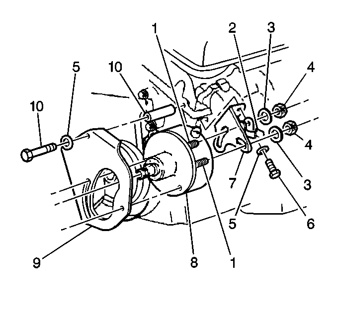
- Remove the steering hoses
at the pump (8).
- Loosen the pump drive belt front bolts (1).
- Loosen the pump drive belt rear nuts (4).
- Move the pump inboard.
- Remove the pump drive belt.
- Remove the nuts (4).
- Remove the washers (3).
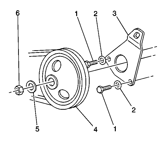
- Use a suitable puller
in order to remove the pulley (4).
- Remove the following components:

- Remove the rear bracket
(7).

- Remove the front bolts
(1).
- Remove the front washers (2).
- Remove the front adjustment bracket (3).

- Remove the pump (8).
Installation Procedure

- Install the pump (8) to
the front bracket (9).

- Install the front adjustment
bracket (3).
- Install the following components to the pump:

- Install the rear bracket
(7)
Notice: Use the correct fastener in the correct location. Replacement fasteners
must be the correct part number for that application. Fasteners requiring
replacement or fasteners requiring the use of thread locking compound or sealant
are identified in the service procedure. Do not use paints, lubricants, or
corrosion inhibitors on fasteners or fastener joint surfaces unless specified.
These coatings affect fastener torque and joint clamping force and may damage
the fastener. Use the correct tightening sequence and specifications when
installing fasteners in order to avoid damage to parts and systems.
- Install the following
components:
Tighten
Tighten the rear bracket mounting bolts to 37 N·m (27 lb ft).
- Install the clip (2).
- Install the following components:

- Install the pulley (4).
- Install the following components:
Tighten
Tighten the pulley nut to 64 N·m (47 lb ft).
- Install the drive belt. Refer to Drive Belt
Replacement
.
- Install the pump mounting bolts (1).
Tighten
Tighten the pump mounting bolts to 37 N·m (27 lb ft).
- Tighten the rear pump mounting nuts (4).
Tighten
Tighten the pump mounting nuts to 26 N·m (19 lb ft).
- Install the power steering hoses.
Tighten
Tighten the hose connections (pressure side) to 28 N·m
(21 lb ft).
- Install the power steering fluid.
- Bleed the system. Refer to
Power Steering System Bleeding
.
Power Steering Pump Replacement Hobourn with LP4 or L21
Removal Procedure
Tools Required
J 42971 Quick Disconnect
Tool
Important: Always clean the connectors and lubricate the tool end in power steering
fluid when inserting into the coupling.
Important: Check all power steering system quick connect connections by trying
to pull the hose assembly out of the fitting using a firm hand tug. Repeat
the step if the connector is pulled out of the male fitting. If the problem
persists, inspect and replace the hose assembly if the quick connect
is damaged.
- Cap the hoses in order to keep dirt from entering the system.
- Tag the hose locations.
- Remove the hoses from the pump.
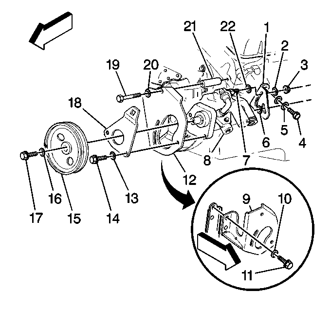
- Loosen the front bolts
(14).
- Loosen the rear nuts (3).
- Move the pump (8) in order to loosen the drive belt.
- Remove the drive belt. Refer toDrive Belt Replacement
.
- Remove the following components:
| 8.1. | The pulley retaining bolt (17) |
| 8.2. | The captive washer (16) |
- Use a suitable puller in order to remove the pulley .
- Remove the following components:
| 10.1. | The rear nuts (3) and washers (2) |
| 10.2. | The rear bracket retaining bolts (4) and washers (5) |
- Remove the rear bracket (1).
- Remove the washer (22) on the rear stud.
- Remove the following components:
| 13.1. | The front bolts (14) |
- Remove the front adjustment bracket (18).
- Remove the pump (8).
Installation Procedure

- Install the pump (8) to
the front bracket (12).
- Install the front adjustment bracket (18).
- Install the front bolts (14) and washers (13)
- Install the rear washer (22) on the stud.
- Install the rear bracket (9).
- Install the washers (10).
Notice: Use the correct fastener in the correct location. Replacement fasteners
must be the correct part number for that application. Fasteners requiring
replacement or fasteners requiring the use of thread locking compound or sealant
are identified in the service procedure. Do not use paints, lubricants, or
corrosion inhibitors on fasteners or fastener joint surfaces unless specified.
These coatings affect fastener torque and joint clamping force and may damage
the fastener. Use the correct tightening sequence and specifications when
installing fasteners in order to avoid damage to parts and systems.
- Install the bolts (11).
Tighten
Tighten the rear bracket bolts to 37 N·m (27 lb ft).
- Install the rear washer (2) and nut (3).
- Install the pulley (15).
- Install the captive washer (16).
- Install the pulley bolt (17).
Tighten
Tighten the pulley bolt to 24 N·m (18 lb ft).
- Install the drive belt. Refer toDrive Belt
Replacement
.
- Tighten the front bolts (14) and the rear nuts.
Tighten
| • | Tighten the front bolts to 37 N·m (27 lb ft). |
| • | Tighten the rear nuts to 26 N·m (19 lb ft). |
- Install the power steering fluid.
- Bleed the system. Refer to
Power Steering System Bleeding
.
Power Steering Pump Replacement Hobourn with LG5 and JE3
Removal Procedure
Tools Required
J 42971 Quick Disconnect
Tool
Important: Always clean the connectors and lubricate the tool end in power steering
fluid when inserting into the coupling.
Important: Check all power steering system quick connect connections by trying
to pull the hose assembly out of the fitting using a firm hand tug. Repeat
the step if the connector is pulled out of the male fitting. If the problem
persists, inspect and replace the hose assembly if the quick connect
is damaged.
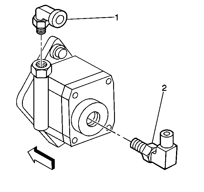
- Cap the hoses in order
to keep dirt out of the system.
- Tag the hose locations (1, 2).
- Remove the power steering hoses at the pump.
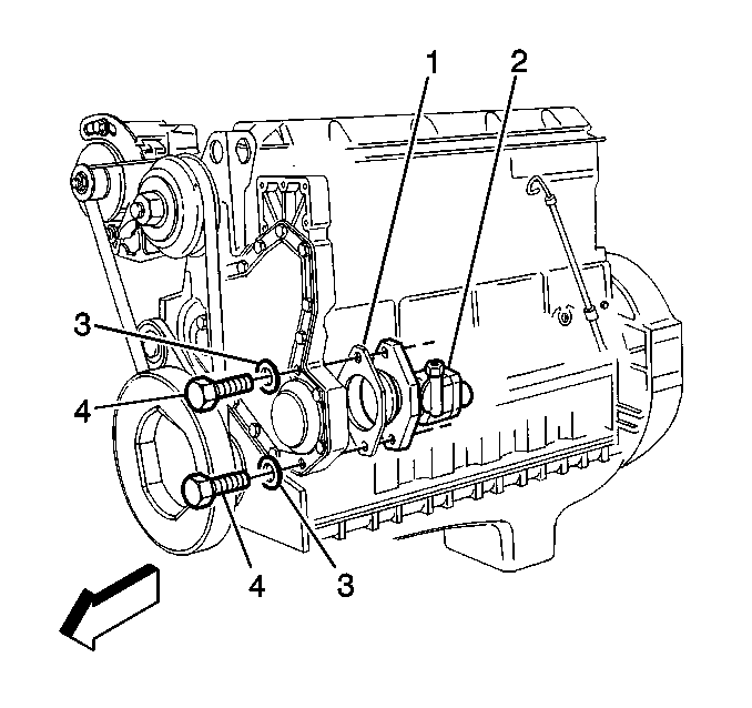
- Remove the following components:
Installation Procedure

- Install the gasket. (1).
- Install the pump (2).
- Install the washers (3).
Notice: Use the correct fastener in the correct location. Replacement fasteners
must be the correct part number for that application. Fasteners requiring
replacement or fasteners requiring the use of thread locking compound or sealant
are identified in the service procedure. Do not use paints, lubricants, or
corrosion inhibitors on fasteners or fastener joint surfaces unless specified.
These coatings affect fastener torque and joint clamping force and may damage
the fastener. Use the correct tightening sequence and specifications when
installing fasteners in order to avoid damage to parts and systems.
- Install the bolts
(4).
Tighten
Tighten the pump mounting bolt to 73 N·m (54 lb ft).

- Install the power steering
hoses.
Note the hose locations, (1, 2).
- Install the power steering fluid.
- Bleed the system. Refer to
Power Steering System Bleeding
.
Power Steering Pump Replacement Hobourn with LG5 and JE4
Removal Procedure
Tools Required
J 42971 Quick Disconnect
Tool
Important: Always clean the connectors and lubricate the tool end in power steering
fluid when inserting into the coupling.
Important: Check all power steering system quick connect connections by trying
to pull the hose assembly out of the fitting using a firm hand tug. Repeat
the step if the connector is pulled out of the male fitting. If the problem
persists, inspect and replace the hose assembly if the quick connect
is damaged, the seals or quick connect release sleeve and collar. These
are available through GM SPO.
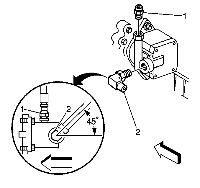
- Cap the hoses in order
to keep dirt out of the system.
- Tag the hose locations (1, 2).
- Remove the power steering hoses at the pump.
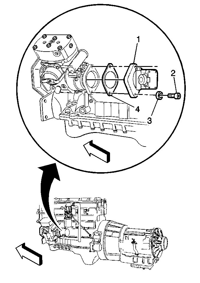
- Remove the following components:
Installation Procedure

- Install the gasket (4).
- Install the pump (1).
- Install the washers (3).
Notice: Use the correct fastener in the correct location. Replacement fasteners
must be the correct part number for that application. Fasteners requiring
replacement or fasteners requiring the use of thread locking compound or sealant
are identified in the service procedure. Do not use paints, lubricants, or
corrosion inhibitors on fasteners or fastener joint surfaces unless specified.
These coatings affect fastener torque and joint clamping force and may damage
the fastener. Use the correct tightening sequence and specifications when
installing fasteners in order to avoid damage to parts and systems.
- Install the bolts.
Tighten
Tighten the pump mounting bolts to 73 N·m (55 lb ft).

- Install the steering hoses
(1, 2).
- Install the power steering fluid.
- Bleed the system. Refer to
Power Steering System Bleeding
.


