Power Steering System Bleeding Remote Reservoir
Bleeding Procedure
Tools Required
J 42971 Quick Disconnect
Tool
Important: Always clean the connectors and lubricate the tool end in power steering
fluid when inserting into the coupling.
Important: Check all power steering system quick connect connections by trying
to pull the hose assembly out of the fitting using a firm hand tug. Repeat
the step if the connector is pulled out of the male fitting. If the problem
persists, inspect and replace the hose assembly if the quick connect
is damaged.
Be sure to bleed air from the system when the following actions are
taken:
| • | A power steering pump is installed. |
| • | A fluid hose is connected. |
| | If air is present in the power steering fluid system, the steering system
will be noisy and will operate unsatisfactorily. |
Use only the specified power steering fluid when bleeding or refilling
the system. Refer to
Fluid and Lubricant Recommendations
.
Ensure that the following connections are tightly closed:
| | This action will prevent air from entering the system or fluid leaks. |
| | Ensure that the power steering fluid level is sufficient to maintain
fluid in the reservoir at all times during the bleeding procedure. Refer to
Approximate Fluid Capacities
. |
| • | This procedure is designed to minimize the chance of fluid aeration
or overflow during the bleeding process. |
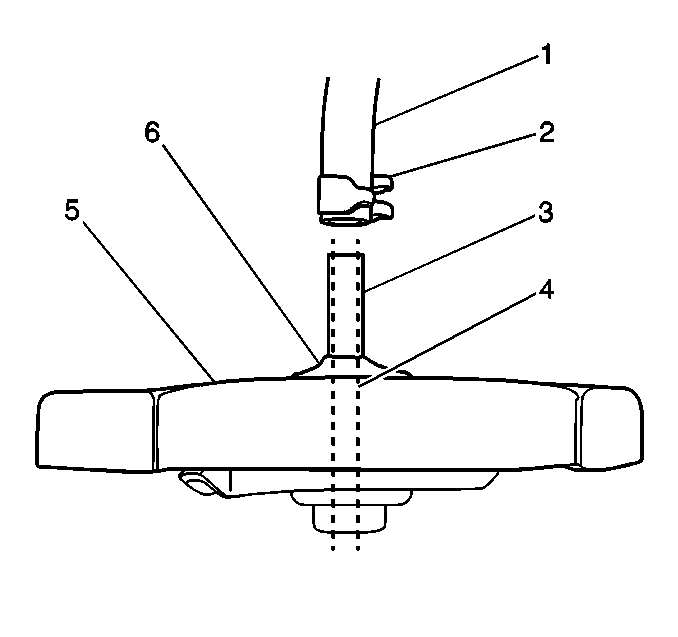
Important: Do not install the reservoir cap during the bleeding procedure on remote
reservoir models. Air may be trapped in the system. When the engine is stopped,
power steering fluid will be forced out through the breather
hole in the cap.
- Install one of the following caps in order to prevent overflow:
| • | An integral reservoir cap GM P/N 26018909 |
| • | A fabricated overflow cap |
| • | Fabricate an overflow cap from a reservoir cap (5) with a 1.8 M
(6 ft) hydraulic hose (1) attached at the center. |
- Raise the front end of the vehicle off the ground until the wheels
are free to rotate.
Refer to
Lifting and Jacking the Vehicle
in General Information.
- Remove the drag link at the pitman arm.
Important: The following actions may cause increased steering gear travel:
| • | Removal of the drag link at the pitman arm |
| • | Turning the steering wheel from stop to stop |
- It may be necessary to readjust the poppet valve in the TRW Ross power
steering gear. Use the poppet adjusting screw assembly kit in order to readjust
the poppet valve. Refer to
Power Steering Gear Poppet Valve Readjustment
.
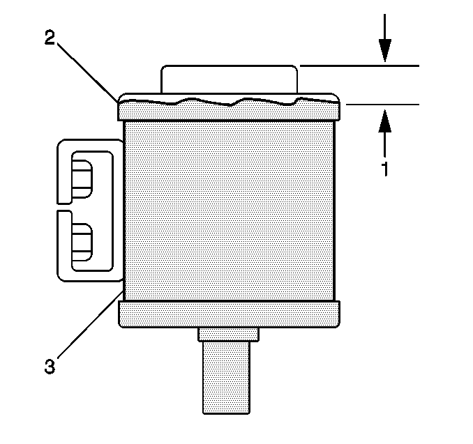
- Fill the reservoir (2)
to within 13 mm (.5 in) (1) of the top.
- Leave the cap off.
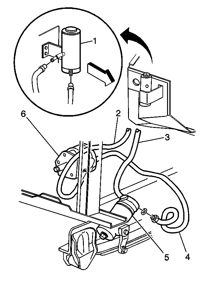
- Use the following steps
in order to remove trapped air from the hose (3):
| 7.1. | Squeeze the reservoir hose (3) near the pump (6). |
| 7.2. | Continue to squeeze the hose toward the reservoir (1). |

- Fill the reservoir (3).
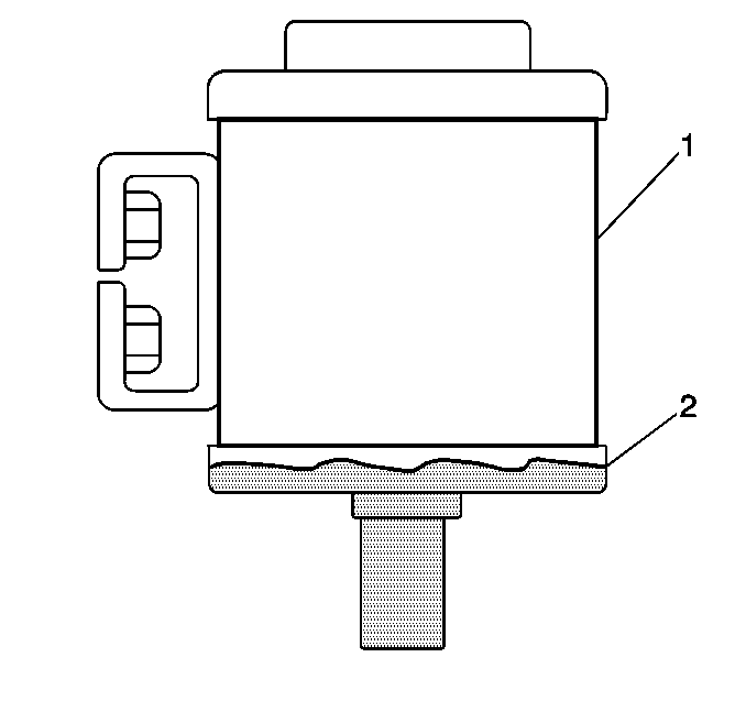
Important: Have an assistant ready to pour power steering fluid into the reservoir
(1) as soon as the engine starts. This action will prevent the entry of air
in to the system.
- Use the following steps in order to fill the reservoir:
| 9.3. | Run the engine for approximately three seconds |

- Wait one minute. Fill
the reservoir (3) again.
- Repeat steps 8 and 9 two more times.
- Start the engine.

- Inspect the fluid level
(2).
The fluid level should be maintained at the bottom of the reservoir
(1) in order to prevent pump aeration throughout the remainder of the procedure.
- Pump the brake pedal on hydraulic brake booster equipped vehicles.
Pump at least three times with the engine running in order to eliminate
air from the brake booster.
- Run the engine at idle.
Notice: Do not turn steering wheel hard or fast against wheel stops. Excessive
force or speed can cause high hydraulic pressure or fluid overheating that
can damage the gear and/or the power steering pump.
- Turn the steering wheel, slowly to the right.
- Turn the steering wheel to the right until the right wheel stop
is lightly contacted.
- Turn the steering wheel to the left one-half turn.
- Turn the steering wheel to the right, lightly against the wheel
stop.
- Repeat the procedure five times.
- Turn the steering wheel, slowly to the left.
| 21.1. | Turn the steering wheel to the left until the left wheel stop
is lightly contacted. |
| 21.2. | Turn the steering wheel to the right one-half turn. |
| 21.3. | Turn the steering wheel to the left, lightly against the wheel
stop. |
| 21.4. | Repeat the procedure five times. |
- Maintain the oil level in the reservoir (1) just above the bottom
of the reservoir (2).
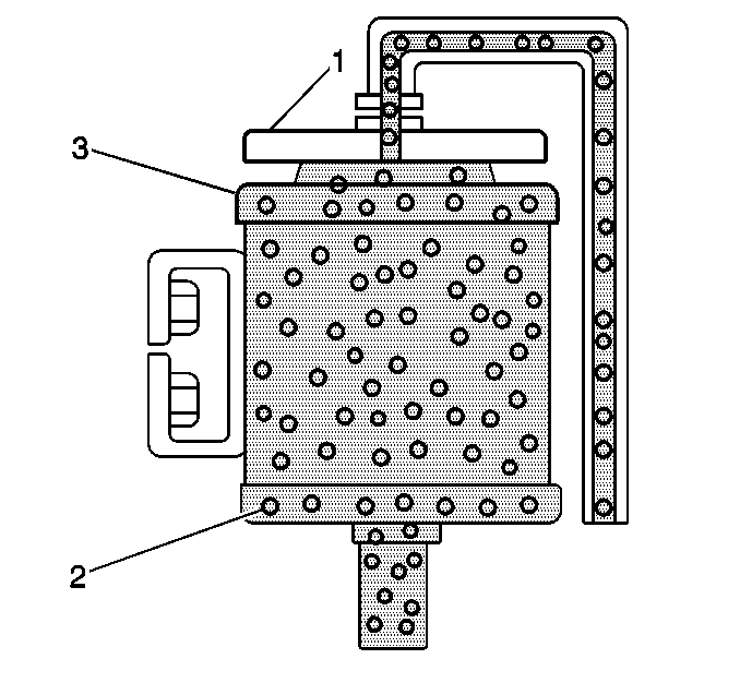
- Turn the steering wheel
to the center position.
| 23.2. | Install the fabricated cap (1). |
| 23.3. | Place the end of the hose in a suitable container. |
| 23.4. | Turn off the engine for at least one minute. |
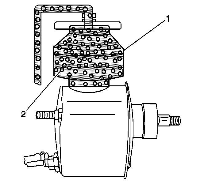
| 23.5. | Allow the air to bubble (3) out through the overflow hose on
the cap (1). |
- Remove the overflow cap.
- Start the engine.

- Maintain the fluid level
(2) just above the bottom of the reservoir (1).
- Repeat steps 10 through 23.
Repeat the steps as many times as necessary until there is no more than
a 25 mm (1 in) rise in the reservoir fluid level with the engine
stopped.
- Remove the safety stands.
- Lower the vehicle.
- Start the engine.
- Idle the engine at 1500 RPM.
- Turn the wheels right and left lightly against the wheel stops.
Continue the procedure for 2 minutes. This should eliminate the any
of the air left in the system.
- Shut off the engine.
- Inspect for leaks.
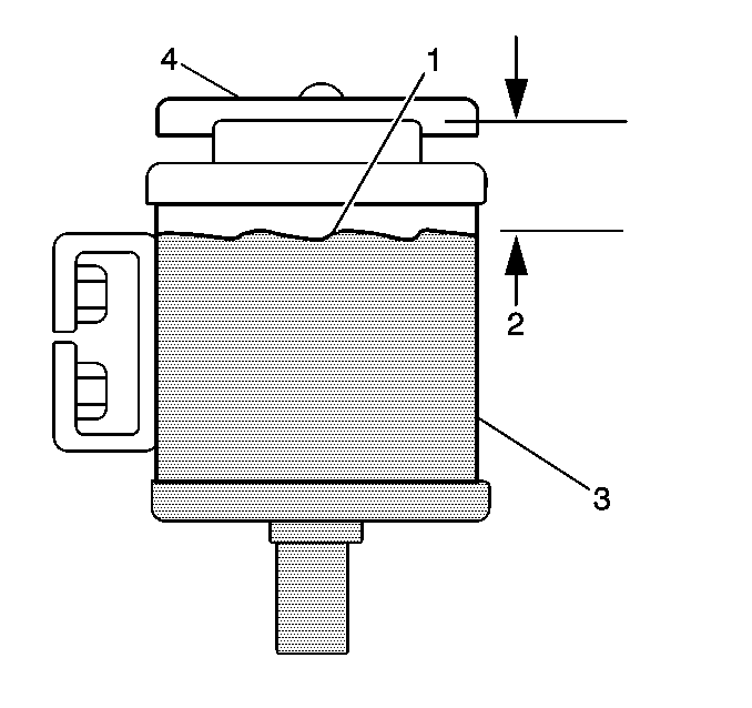
- Fill the reservoir (3)
to the final level (1).
Power Steering System Bleeding Integral Reservoir
Bleeding Procedure
Be sure to bleed air from the system when the following actions are
taken:
| • | A power steering pump is installed
|
| • | A fluid hose is connected
|
If air is present in the power steering fluid system, the steering system
will be noisy and will operate unsatisfactorily.
| • | Ensure that the following connections are tightly closed: |
| - | This action will prevent air from entering the system or fluid leaks. |
| • | Ensure that the power steering fluid level is sufficient to maintain
fluid in the reservoir at all times during the bleeding procedure. Refer to
Approximate Fluid Capacities
. |
| • | This procedure is designed to minimize the chance of fluid aeration
or overflow during the bleeding process. |

- Install one of the following
caps in order to prevent overflow:
| • | An integral reservoir cap GM P/N 26018909 |
| • | A fabricated overflow cap |
| • | Fabricate an overflow cap from a reservoir cap (5) with a 1.8 M
(6 ft) hydraulic hose (1) attached at the center. |
- Raise the front end of the vehicle off the ground until the wheels
are free to rotate. Support the vehicle with suitable safety stands. Refer
to
Lifting and Jacking the Vehicle
in General Information.
- Remove the drag link at the pitman arm.
Important: The following actions may cause increased steering gear travel:
| • | Removal of the drag link at the pitman arm |
| • | Turning the steering wheel stop to stop |
- Use the poppet adjusting screw assembling kit in order to readjust the
poppet valve. Refer to
Power Steering Gear Poppet Valve Readjustment
.
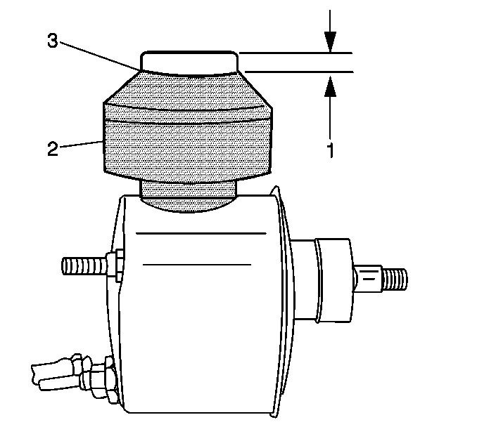
- Fill the reservoir (2)
to within 13 mm (0.5 in) (1) of the top.
- Leave the cap off.
- Use the following steps in order to remove trapped air from the
hose:
| 7.1. | Squeeze the return hose near the gearbox. |
| 7.2. | Continue to squeeze the hose toward the reservoir (2). |
- Recheck the reservoir fluid level.
Important: Have an assistant ready to pour power steering fluid into the reservoir
(2) the moment the engine starts in order to prevent the entry of air in to
the system.
- Use the following steps in order to fill the reservoir:
| 9.3. | Run the engine for approximately three seconds. |
| 9.4. | Shut the engine off. |
- Wait one minute and fill the reservoir (3) again.
- Repeat steps 7 and 8 two more times.
- Start the engine.
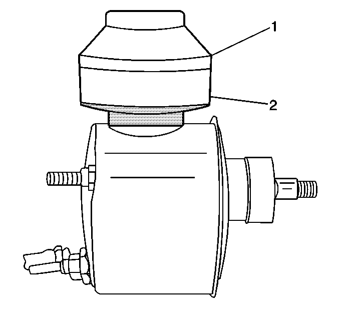
- Inspect the fluid level
(2).
The fluid level should be maintained at the bottom of the reservoir
(1) in order to prevent pump aeration throughout the remainder of the procedure.
- Pump the brake pedal on hydraulic brake booster equipped vehicles.
Pump at least three times with the engine running in order to eliminate air
from the brake booster.
- Run the engine at idle.
Notice: Do not turn steering wheel hard or fast against wheel stops. Excessive
force or speed can cause high hydraulic pressure or fluid overheating that
can damage the gear and/or the power steering pump.
- Turn the steering wheel, slowly to the right.
| 16.1. | Turn the steering wheel to the right until the right wheel stop
is lightly contacted. |
| 16.2. | Turn the steering wheel to the left one-half turn. |
| 16.3. | Turn the steering wheel to the right, lightly against the wheel
stop. |
| 16.4. | Repeat the procedure five times. |
- Turn the steering wheel, slowly to the left.
| 17.1. | Turn the steering wheel to the left until the left wheel stop
is lightly contacted. |
| 17.2. | Turn the steering wheel to the right one-half turn. |
| 17.3. | Turn the steering wheel to the left, lightly against the wheel
stop. |
| 17.4. | Repeat the procedure five times. |
- Maintain the oil level in the reservoir (1) just above the bottom
of the reservoir (2).
- Turn the steering wheel
to the center position.
| 19.2. | Install the fabricated cap. |
| 19.3. | Place the end of the hose in a suitable container. |
| 19.4. | Turn off the engine for at least one minute. |
| 19.5. | Allow the air to bubble (2) out through the overflow hose on the
cap . |
- Remove the overflow cap.
- Start the engine.

- Maintain the fluid level
(2) just above the bottom of the reservoir (1).
- Repeat steps 10 through 19.
Repeat the steps as many times as necessary until there is no more than
a 25 mm (1 in) rise in the reservoir fluid level with the engine
stopped.
- Remove the safety stands.
- Lower the vehicle.
- Start the engine.
- Idle the engine at 1500 RPM.
- Turn the wheels right and left lightly against the wheel stops.
Continue the procedure for 2 minutes. This should eliminate the any
of the air left in the system.
- Shut off the engine.
- Inspect for leaks.
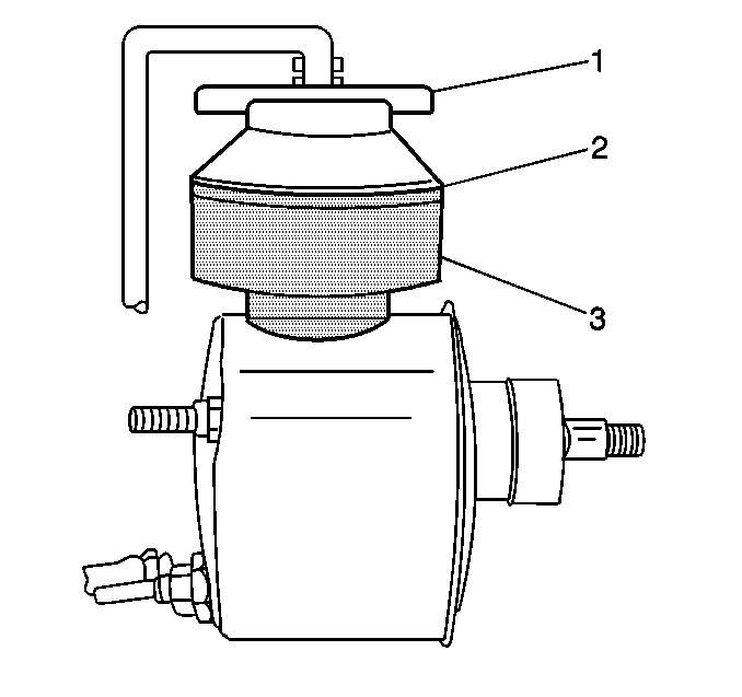
- Fill the reservoir (3)
to the final level (2).


