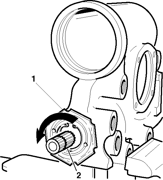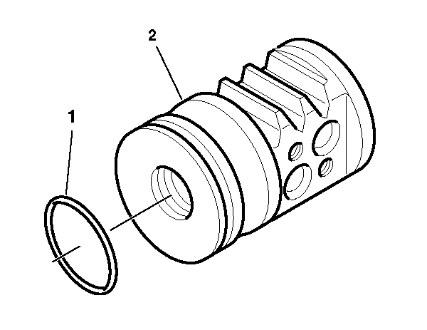
- Lubricate the following
items with power steering fluid while installing to the rack piston (2):
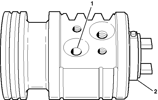
- Install the worm shaft (2)
to the rack piston outside of the steering gear housing.
- Fully seat the worm shaft (2) to the rack piston.
- Align the worm shaft (2) spiral groove with the rack piston
ball return guide hole (1).
Important: Reinstall all of the rack piston balls in the rack piston. Improper
rack piston ball installation may result in personal injury. The black rack
piston balls are smaller than the silver rack piston balls. Install the black
and the silver rack piston balls alternately into the rack piston and the
ball guide to maintain the rack piston to the worm shaft preload.
- Lubricate the rack piston balls with power steering fluid.
- Insert the rack piston balls through the ball return guide hole (1)
while turning worm shaft (2) counterclockwise in order to install the
rack piston balls into the rack piston.
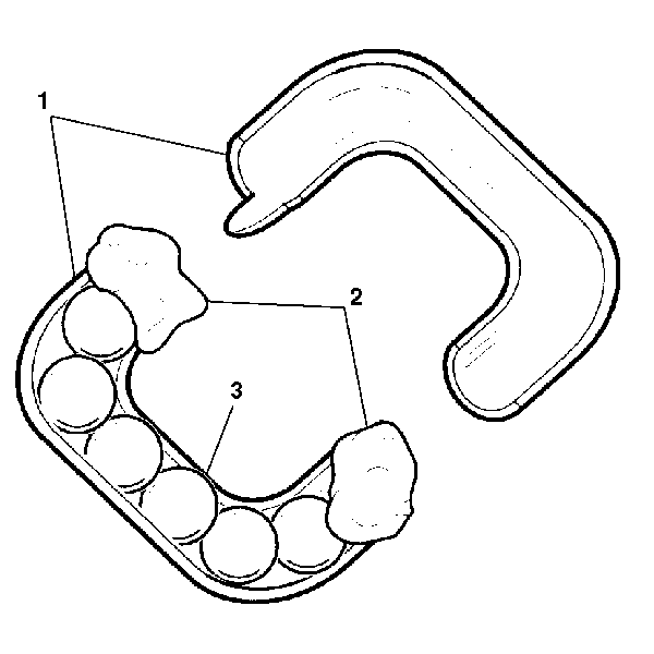
- Install the remaining
rack piston balls (3) into the ball guide (1) use grease (2)
at each end in order to retain the rack piston balls.
Notice: Use the correct fastener in the correct location. Replacement fasteners
must be the correct part number for that application. Fasteners requiring
replacement or fasteners requiring the use of thread locking compound or sealant
are identified in the service procedure. Do not use paints, lubricants, or
corrosion inhibitors on fasteners or fastener joint surfaces unless specified.
These coatings affect fastener torque and joint clamping force and may damage
the fastener. Use the correct tightening sequence and specifications when
installing fasteners in order to avoid damage to parts and systems.
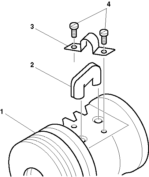
- Install the ball
guide (2) to the rack piston (1).
- Install the ball guide clamp (3).
- Install the screws (4).
Tighten
Tighten the screws to 58 N·m (43 lb in).
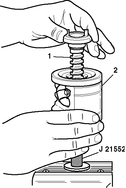
- Insert J 21552
into the bore of the rack piston (2)
while turning the worm shaft (1) counterclockwise. The turning of the
worm shaft (1) forces the rack piston (2) onto J 21552
. The rack piston balls remain in
place.
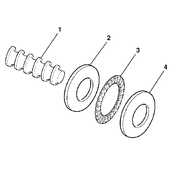
- Install the flat races (2)
and (4) the roller thrust bearing (3) onto the worm shaft (1).
- Install the worm shaft (1) to the steering gear housing.
- Install the valve. Refer to Steering Gear Thrust Support Replacement - Off Vehicle (Saginaw - 710 Model)
.
- Install the rack piston to the worm shaft (1) from J 21552
, using J 8947
to compress the seals.
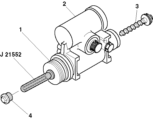
Important: Reinstall all of the rack piston balls into the rack piston. Improper
rack piston ball installation may result in personal injury.
- Hold J 21552
tightly
against the worm shaft (3) .
- Turn the stub shaft clockwise until the rack piston (1)
is seated on the worm shaft (3).
- Remove J 21552
from the rack piston (1).
- Install the rack piston plug (4).
Tighten
Tighten the rack piston plug (4) to 150 N·m (111 lb ft).
- Install the steering gear housing end plug. Refer to
Steering Gear Housing Plug Replacement - Off Vehicle
.
- Install the pitman shaft.
- Install the side cover. Refer to
Steering Gear Pitman Shaft and Housing Cover Replacement - Off Vehicle
.
