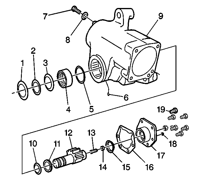
- Install the retaining
ring (5) into the groove closest to the side cover end of the bearing bore,
if previously removed.
- Install the roller bearing (4) from the trunnion end of the bearing
bore.
Press the bearing bore installation end of the J 37071 from the J 37612-A
against the lettered
end of the bearing shell. Press until the bearing is seated against the retaining
ring, if previously removed.
- Lubricate the bearing bore.
- Ensure that the following conditions exist:
| • | The housing is square with the press base. |
| • | The bearing is not cocked. |
- Install the washer (10) into the side cover side of the housing
seal bore. Ensure that the diameter is piloted into the retaining ring (5).
- Install the NEW seal (11) onto the J-37071 from the J 37612-A
. Ensure that the lip with the spring
is toward the shoulder of the tool.
- Install the J-37071 from the J 37612-A
into the washer and the bearing.
Use a force of 46-362 kg (100- 800 lb).
Apply the force until the seal is seated against the washer.
- Install the NEW seal (3) . Ensure that the seal lip faces out.
- Install the retaining ring (2).
- Pack the area between the seal (7) and the output shaft seal (9)
with clean high temperature industrial grease.
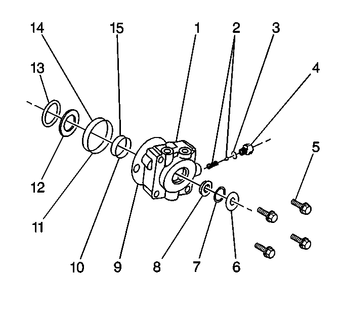
- Install new lightly oiled valve housing O-ring into the housing (1)
in the mounting face groove.
- Install new lightly oiled valve housing seal (9) in the
mounting face groove.
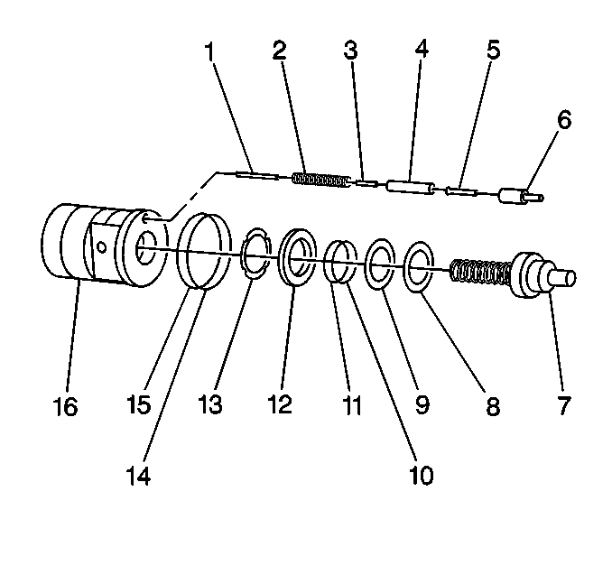
- Install the poppet assemblies,
if they were removed.
- Ensure that the following components are free of thread sealing
compound:
| • | The two threaded poppet holes in the rack piston (16) |
| • | The poppet adjuster seat and sleeve assemblies (6) |
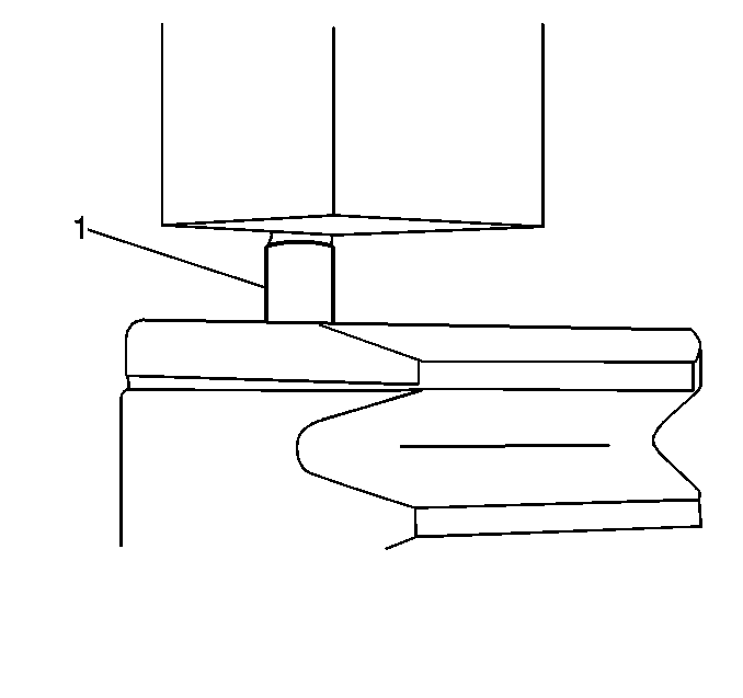
- Reset the automatic poppet
adjuster seat and the sleeve assembly (1) if it was removed. (New service
replacement parts do not need to be reset.)
Use the following steps to reset the automatic poppet adjuster seat
and the sleeve assembly:
| 15.1. | Reverse the automatic poppet adjuster. |
| 15.2. | Ensure that the slotted end goes inward. |
| 15.3. | Screw the adjuster seat loosely into the piston to its full thread
length. |
- Press the adjuster seat into the adjuster sleeve (1).
Apply a force of 227-1134 kg (500-2500 lb)
until the shoulder of the adjuster seat bottoms against the adjuster sleeve.
- Remove the following components from the rack piston:
| 17.2. | The sleeve assembly |
- Repeat this procedure for the other poppet adjuster seat and sleeve
assembly.

- Insert a 9.52 x 152 mm
(3/8 x 6 in) drill rod through the poppet seat hole
at the opposite end of the rack piston.
Reset the poppet adjuster seat and sleeve assembly (6) that was left
in the rack piston (16) for automatic poppet adjustment.
- Press the adjuster seat in until it bottoms against the adjuster
sleeve (6).
Notice: Do not allow thread locking compounds to get on the adjuster seat component
of the adjuster seat and sleeve or the adjustment function of this assembly
will be adversely affected.
- Apply Loctite T ™primer or the equivalent to the following components:
| 21.1. | The threaded poppet holes in the rack piston |
| 21.2. | The threads on the adjuster seat |
| 21.3. | The threads on the sleeve assemblies |
- Allow the Loctite to dry for ten minutes.
- Apply Loctite RC680™ or the equivalent to the above components.
Caution: Wear eye protection while assembling poppets. Spring loaded poppets
could eject and cause personal injury.
- Place the rack piston (16) into a soft-jawed vise.
- Turn a poppet adjuster seat and sleeve assembly (6) into one poppet
hole.
Ensure that the slotted end faces outward.
- Install the following to the opposite end:
| 26.2. | The poppet spring (2) |
| 26.5. | The other poppet (5) |
| 26.6. | The other adjuster seat and sleeve assembly (6) |
Notice: Use the correct fastener in the correct location. Replacement fasteners
must be the correct part number for that application. Fasteners requiring
replacement or fasteners requiring the use of thread locking compound or sealant
are identified in the service procedure. Do not use paints, lubricants, or
corrosion inhibitors on fasteners or fastener joint surfaces unless specified.
These coatings affect fastener torque and joint clamping force and may damage
the fastener. Use the correct tightening sequence and specifications when
installing fasteners in order to avoid damage to parts and systems.
- Use the J 36452
in order to install the poppet adjuster seat and the sleeve assemblies.
Tighten
Tighten the poppet adjuster seat and sleeve assemblies to 13 N·m
(115 lb in).
- Place the rack piston (16) onto a pedestal. Ensure that the following
conditions exist:
| 28.1. | The ball guide holes face upward |
| 28.2. | The rack piston worm bore is high enough to permit assembly of
the worm end of the input shaft (7). |
- Install the new back up seal (15). Do not overstretch.
- Install a new seal (14) on the rack piston (16). Do not overstretch.
- Install the worm end of the input shaft to the maximum depth without
the valve housing contacting the upper poppet.
- Install the NEW ball return guide halves fully into the rack piston.
- Line up the rack piston ball guide holes with the worm ball track
grooves.
- Rotate the input shaft (7) slightly, if necessary.
Do not seat the guides with a hammer.
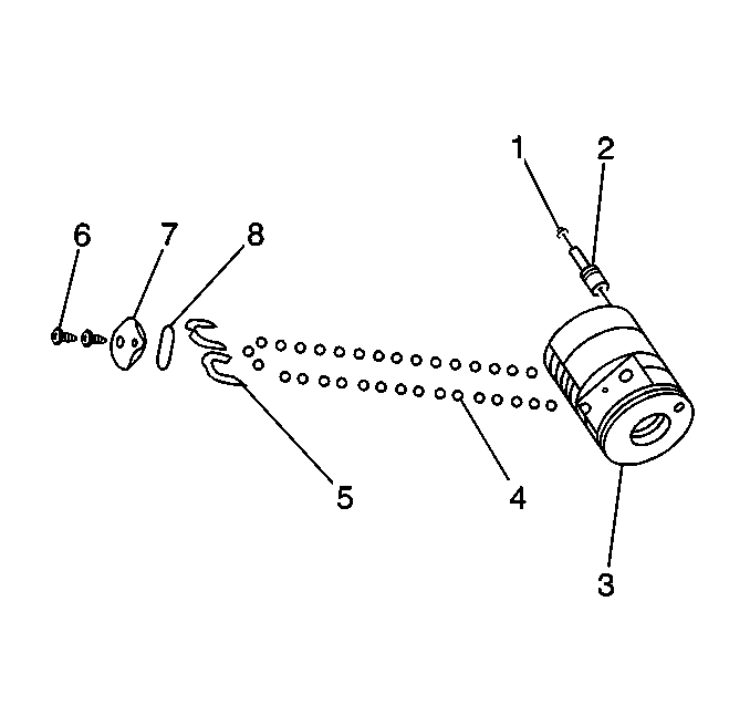
- Install the thirty two
balls (4) into the ball return guides (5).
- Discard the balls (4) and the service kit if the following components
are new:
| • | The valve or worm assembly |
- Hold the ball return guides (5) firmly in place while adding the
balls (4).
Hold the ball return guides until the guide cap (7) is retained
in the rack piston (3).
- Insert as many of the steel balls (4) as possible through the
hole in the top of the ball return guides.
- Lift up on the valve housing and the input shaft assembly in order
to allow some of the balls to follow the ball track down and under the worm.
- Rotate the worm in order to pull the balls down and around the
ball track path.
Continue this process until the 32 balls are in the ball track guide
path.
Do not allow the valve housing face to contact the poppet adjuster or
to move more than 69.1 mm (2.72 in) from the upper end of the
rack piston during these procedures.
- Install the new ball return guide cap seal (8).
- Install the ball return guide cap (7).
- Install the NEW screws (6).
Tighten
Tighten the screws alternately to 25 N·m (18 lb ft).
- Rotate the worm shaft from one end of travel to the other.
Do not allow the poppet adjuster to contact the valve housing.
Do not move the valve housing pilot face more than 69.1 mm (2.72 in)
from the input end of the rack piston (3).
These actions will ensure that the balls (4) are installed properly.
- Attempt to rotate the shaft.
If the shaft cannot be rotated, remove and reassemble the balls (4).
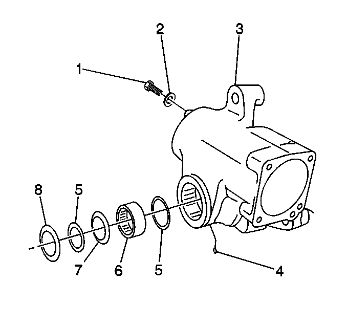
- Install the housing (3)
into the vise.
- Install the washer and the poppet stop screw (1), if removed.
Tighten
Tighten the screw to 55 N·m (41 lb ft).

- Add clean oil to the following
components:
| • | The housing cylinder bore |
- Install the rack piston (16) into the bore.
Ensure that the teeth face the sector shaft cavity.
- Position the rack piston (16) on the worm. Leave a gap of 10-13 mm
(3/8-½ in) between the valve housing and the upper
adjuster seat and sleeve assembly (6).
Ensure that the valve housing cylinder feed hole and the seal ring line
up with the gear housing feed hole. Do not allow the rack piston poppet adjuster
seat and sleeve to bottom against the internal poppet stops in the
steering gear until the assembly is installed into the vehicle.

- Install the valve housing bolts (5).
Tighten
| • | Tighten the bolts alternately to 149 N·m (110 lb ft). |
| • | Tighten the bolts alternately to 109 N·m (80 lb ft). |
- Install the O-ring (3), if removed.
- Install the relief valve (2), if removed.
- Assemble the small end of the tapered spring on the pin on the
other part of the relief valve (2).
Insert the assembly into the relief valve cap cavity. Insert the tapered
spring end first.
- Turn the relief valve cap (4) as assembled into the valve housing.
Tighten
Tighten the relief valve cap to 41 N·m (30 lb ft).
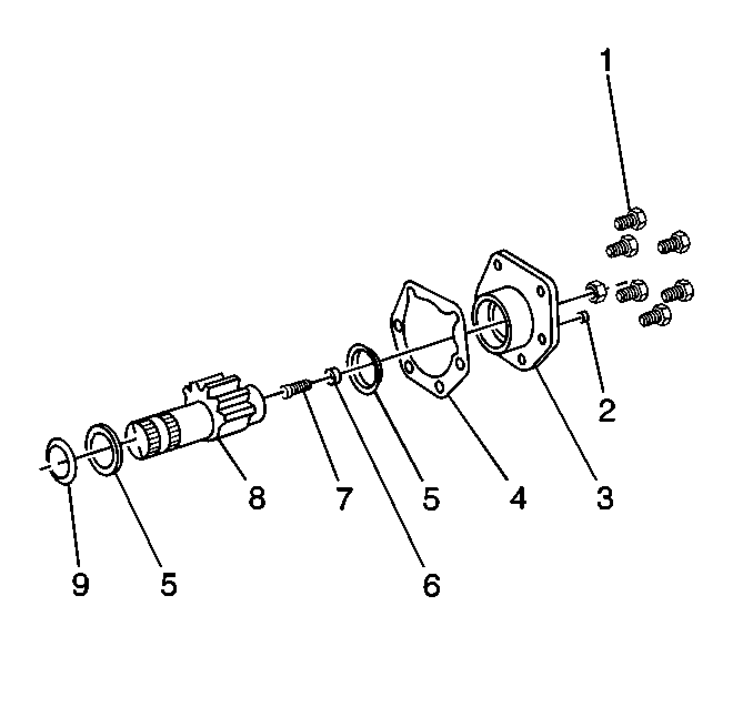
- Install the sector shaft
(8) in a soft jaw vise by gripping the serrated end (if the adjusting screw
was removed).
- Coat the expanded end of the new adjusting screw (7) with a suitable
grade of wheel bearing grease.
- Insert the screw (7) into the recess in the end of the sector
shaft (8).
- Thread a new sector shaft screw retainer into the sector shaft
(8).
- Adjust the screw (7) in order to permit the following conditions:
| • | Free rotation of the sector shaft adjusting screw (7) by hand |
| • | End play of 0-0.05 mm (0.002 in) |
- Use a suitable punch in order to stake the new retainer (6) into
the two slots provided.
If the retainer is broken or cracked during the staking, replace the
retainer.
- Inspect the freedom of the adjusting screw (7) movement and the
end play.
- Coat the bushing in the side cover (3) lightly with oil.
- Install the seal (5) onto the J-37071 from the J 37612-A
with the spring side toward the tool.
- Install the J-37071 from the J 37612-A
into the side cover bushing.
- Press the seal (5) into the side cover housing. Apply a force
of 46-362 kg (100-800 lb) until the seal is seated
against the bottom of the counterbore.
- Install the sector shaft (8) into the side cover (3).
- Coat the short bearing area of the sector shaft (8) lightly
with oil.
- Screw in the sector shaft adjusting screw (7) counterclockwise
until the screw reaches solid height.
- Rotate the adjusting screw (7) ½ turn clockwise. This
action will permit the side cover to rotate freely on the sector shaft.
- Install the jam nut a few threads.
- Install the vent plug (2) until the plug is flush.
- Install the side cover gasket (4) to the side cover. Use clean
grease in order to hold the gasket (4) in place.
- Install the sector shaft (8) and the side cover assembly into
the gear housing.
- Rotate the input shaft in order to position the space between
the second and the third tooth of the four teeth on the rack piston is in
the center of the sector shaft (8) opening.
Important: If the rack piston is not centered when the sector shaft is installed,
gear travel will be severely limited in one direction.
- Clean off any of the old tape on the sector shaft (8) serrations.
- Retape the serrations and the bolt groove with one layer of masking
tape. If the sector shaft (8) serrations are not properly taped, the serrations
will damage the output seal (5).
- Ensure that the center tooth of the sector shaft (8) engages the
center space of the rack piston.
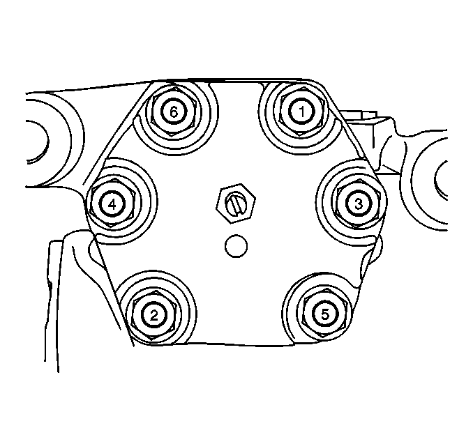
- Install the special side
cover bolts.
Tighten
| • | Tighten the bolts in sequence shown (1-6) to 312 N·m
(230 lb ft) (dry fasteners). |
| • | Tighten the bolts in sequence shown (1-6) to 231 N·m
(170 lb ft) (lubricated fasteners). |
- Install the seal.
- Remove the tape from the sector shaft.
- Pack the end of the housing trunnion area at the sector shaft
with a clean high temperature grease.
- Apply more grease to the seal prior to installation.
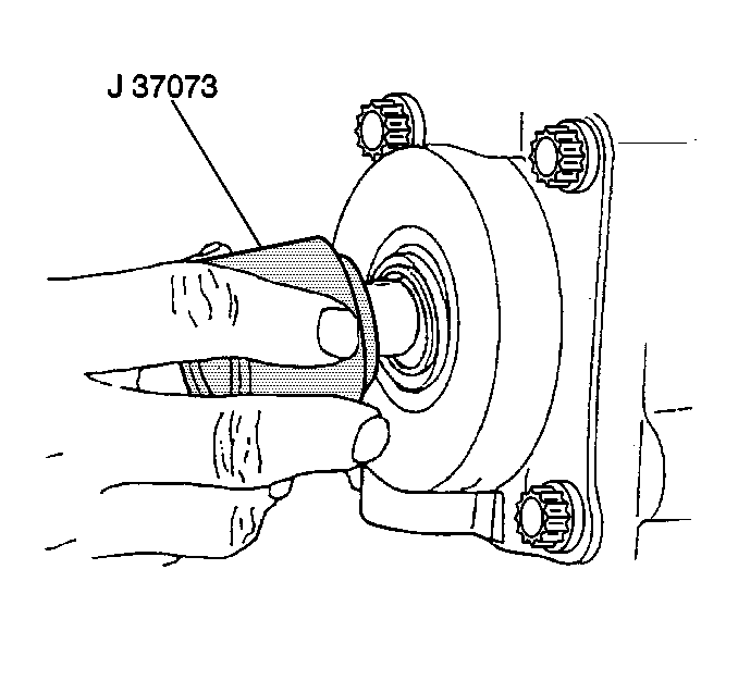
- Use the J-37073 from the J 37612-A
in order to install
the input shaft seal. Ensure that the spring side is installed first.
- Apply clean grease to the seal.
- Install the retaining ring into the groove in the valve housing.
- Install the seal over the input shaft.
- Pack the end of the valve housing bore with clean high temperature
grease GM P/N 1051344.
- Apply some grease to the seal.
- Install the grease fitting, if previously removed.
- Hold a piece of tubing which will clear the head of the fitting
over a new fitting.
- Tap the tubing into the housing.
- Install the automatic bleed hole plug, if previously removed.
Tighten
Tighten the plug to 55 N·m (41 lb ft).
- Install the auxiliary port plug with new O-rings, if previously
removed.
Tighten
Tighten the plug to 41 N·m (30 lb ft).
- Plug all of the ports until the unit is installed in the vehicle.
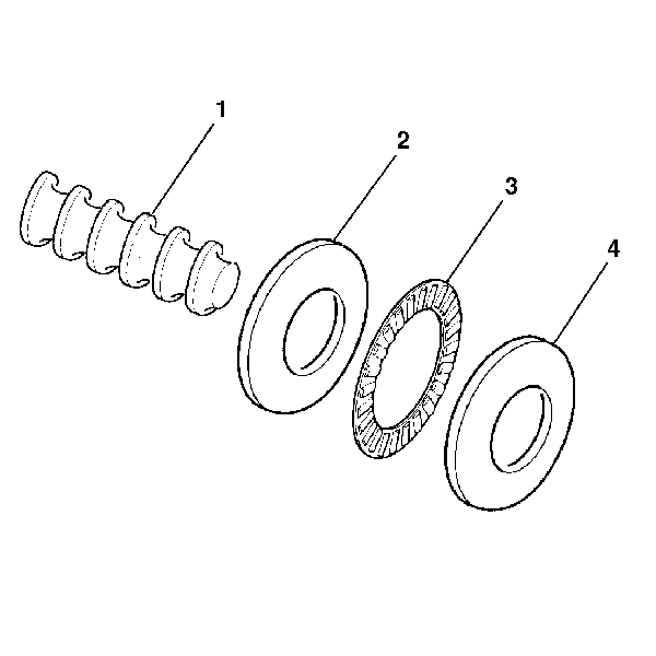
- Lubricate the following
items with power steering fluid:
| • | The roller thrust bearing (3) |
| • | The thrust bearing races (2) (4) |
- Install the following items over the end of the worm shaft (1)
Ensure that the angled surfaces on the thrust bearing races (2) (4)
are parallel to each other:
| • | The thrust bearing race (2) |
| • | The roller thrust bearing (3) |
| • | The thrust bearing race (4) |
- Lubricate the following items with power steering fluid:
| • | The valve body O-ring seals |
| • | The stub shaft O-ring seal |
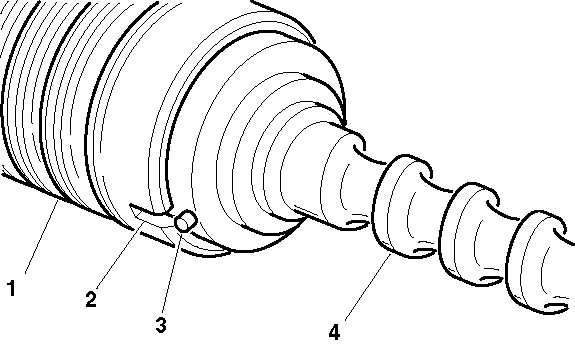
- Align the narrow notch (2)
in the valve body (1) with the pin (3) in the worm shaft cap.
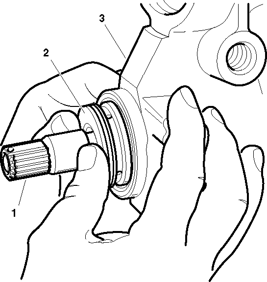
- Install the following
items into the steering gear housing (3) while applying pressure only
to the valve body (2):
| • | The worm shaft assembly |
- Ensure that the valve body (2) is properly seated when
the oil return hole in the steering gear housing is entirely uncovered.
- Apply oil to the O-ring seal.
- Install the O-ring seal onto the thrust support assembly.
- Place J 6222-A
over the end of the stub shaft (1).
- Push the thrust support assembly until the thrust support assembly
seats against the valve body.
Notice: Use the correct fastener in the correct location. Replacement fasteners
must be the correct part number for that application. Fasteners requiring
replacement or fasteners requiring the use of thread locking compound or sealant
are identified in the service procedure. Do not use paints, lubricants, or
corrosion inhibitors on fasteners or fastener joint surfaces unless specified.
These coatings affect fastener torque and joint clamping force and may damage
the fastener. Use the correct tightening sequence and specifications when
installing fasteners in order to avoid damage to parts and systems.
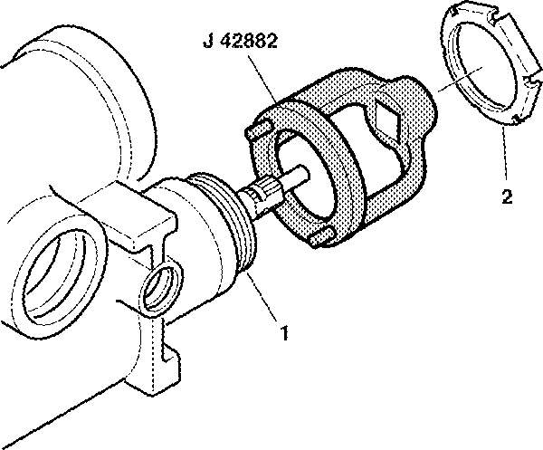
- Install the adjuster
nut assembly (1) into the steering gear housing until the adjuster
nut assembly (1) seats against the thrust support assembly.
Tighten
Tighten the adjuster nut assembly (1) to 28-31 N·m
(21-23 lb ft) using J 42882
.
- Install the coupling shield retainer and lock nut (2).
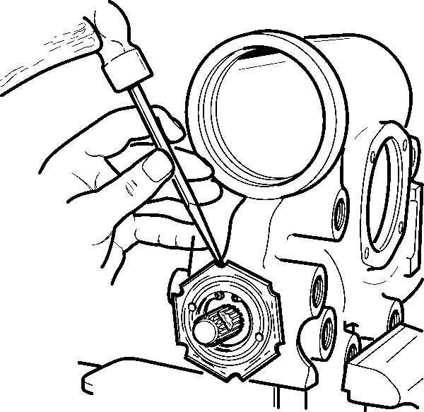
- Tighten the coupling shield
retainer (1) securely using a drift in a notch.
- Hold the adjuster nut assembly in order to maintain the alignment
of the marks while tightening the coupling shield retainer and lock nut (1).
Tighten
Tighten the coupling shield retainer and lock nut (1) to 108 N·m
(80 lb ft).
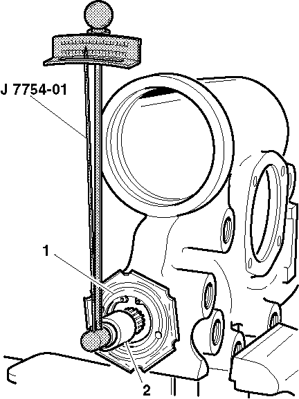
- Inspect the turning torque
using a ¾ inch 12-point socket (2) and J 7754-01
.
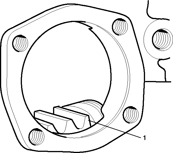
- Insert J 21552
into the bore of the primary rack piston (1).
- Push the primary rack piston (1) into the steering gear
housing with the teeth facing the pitman shaft opening until J 21552
contacts the center of the worm shaft.
- Turn the stub shaft clockwise to thread the primary rack piston
onto the worm shaft while holding J 21552
against the end of the worm.
- After threading the primary rack piston (1) completely
on the worm shaft, remove J 21552
from the primary rack piston (1).
- While looking through the side cover opening, center the primary
rack piston.
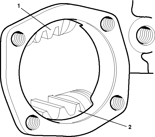
- Install the secondary
rack piston (2) into the steering gear housing with the teeth facing
the pitman shaft opening.
- Align the secondary rack piston teeth (2) with the primary
rack piston teeth (1).
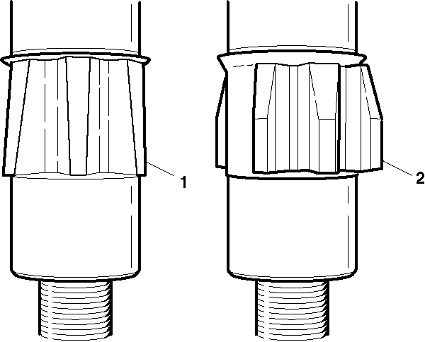
Important: The pitman shaft must be installed with the tapered teeth engaging the
primary rack piston. If this procedure is not followed, you will be impossible
to eliminate the lash between the primary gear teeth.
- Lubricate the area between the seal lips of the pitman shaft seal with
chassis lubricant or an all-purpose grease.
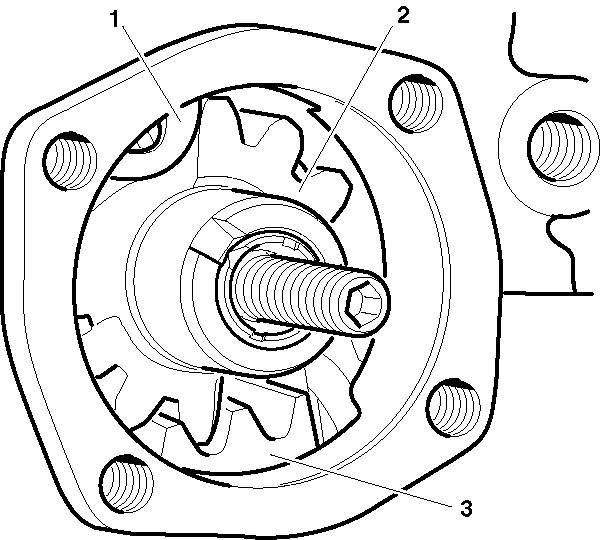
- Install pitman shaft (2)
into the steering gear housing.
- Install the side cover. Refer to
Steering Gear Pitman Shaft and Housing Cover Replacement - Off Vehicle
.
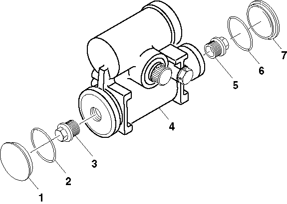
- Install the rack piston
plugs (3) (5) to both cylinders.
Tighten
If the rack piston plugs (3) (5) are aluminum, tighten
the rack piston plugs (3) (5) to 102 N·m (75 lb ft).
If the rack piston plugs (3) (5) are steel, tighten the rack
piston plugs (3) (5) to 115 N·m (85 lb ft).
- Install the housing end plug. Refer to
Steering Gear Housing Plug Replacement - Off Vehicle
.
Notice: Use the correct fastener in the correct location. Replacement fasteners
must be the correct part number for that application. Fasteners requiring
replacement or fasteners requiring the use of thread locking compound or sealant
are identified in the service procedure. Do not use paints, lubricants, or
corrosion inhibitors on fasteners or fastener joint surfaces unless specified.
These coatings affect fastener torque and joint clamping force and may damage
the fastener. Use the correct tightening sequence and specifications when
installing fasteners in order to avoid damage to parts and systems.
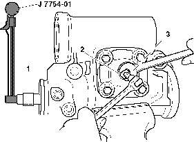
- In order to adjust
the pitman shaft preload, perform the following steps:
| 28.1. | Attach J 7754-01
and a 12-point socket (1) on the stub shaft splines. |
| 28.2. | Turn the stub shaft counterclockwise until bottomed. Count the
number of turns. |
| 28.3. | Turn the stub shaft back ½ the number of turns counted
above to centered position. |
| 28.4. | In order to check the combined ball and bearing preload, turn
the torque wrench (3) through the center of travel. Record the highest
reading. |
Tighten
| • | Tighten the adjuster screw on the pitman shaft until the torque
wrench reading is 0.7-1.1 N·m (6-19 lb in)
higher than the previous reading. The total reading should not exceed 2.25 N·m
(20 lb in) torque. |
| • | Tighten the preload adjuster nut (2) to 90 N·m
(66 lb ft). |
- Reinspect the preload after tightening the preload adjuster nut (2).


