Supply System
The fuel flows through a pre-filter screen in the tank and to the engine through
the fuel supply lines. There is no lift pump in the fuel tanks or on the frame. The
fuel passes through the base plate of the fuel injector control module (FICM) to cool
the module. From the FICM the fuel flows to the fuel filter assembly, which combines
a water separator, a prime pump and a filter element. Within the assembly, there is
also a fuel heater. An integrated hand pump is used to prime the fuel system after
changing the fuel filter or servicing the fuel system. The fuel injection pump at
the front of the engine valley includes a fuel supply pump and a high-pressure pump.
Fuel is drawn to the supply pump from the primary fuel tank by the supply pump and
delivered to the high-pressure pump.
High Pressure System
The much larger section of the pump assembly is the high-pressure fuel injection
pump. The pump is engine-driven by the camshaft gear. From the high-pressure pump,
the fuel flows through the junction block. The junction block routes pressurized fuel
to both common fuel rails. Each common fuel rail supplies one bank of four fuel injectors.
Return System
The Fuel Return System routes fuel from the fuel injectors, the junction block,
and the fuel injection pump. The return fuel travels to the fuel cooler and then to
the fuel tank. This fuel is used to cool and lubricate the injection pump and the
injectors.
Important:
| • | If you were not referred to this test from another diagnostic, do not
perform this procedure. |
| • | Only perform this test when the fuel is more than 18°C (65°F). |
| • | The fuel return volumes vary based on the API rating of the diesel fuel. |
| • | A fuel injector may have high fuel return flow only at higher engine temperatures. |
- Were you Referred here from one of the following diagnostics?
| • | Surges/Chuggles in Symptoms |
| • | Rough, Unstable, or Incorrect Idle in Symptoms |
| • | Fuel Injector Balance Test with Tech 2 |
| - | If you answered Yes, go to the Fuel Pressure Regulator Graphing after
step 48. |
| - | If you answered No, go to Step 2. |
- Remove the air duct from the air cleaner assembly and the turbo inlet.
- Remove the air intake pipe. Refer to
Air Intake Pipe Replacement
.
- Drain the coolant and remove the water outlet tube. Refer to
Water Outlet Tube Replacement
in Engine Cooling.
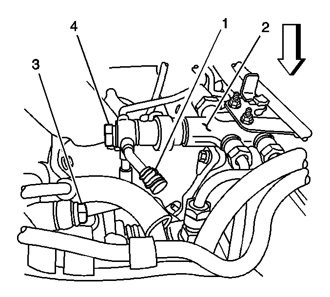
- Remove
the fuel injection pump fuel return rubber hose from the junction block (2). Cap
the fitting on the block with a 3/8 inch rubber cap (1) to prevent
fuel leakage.
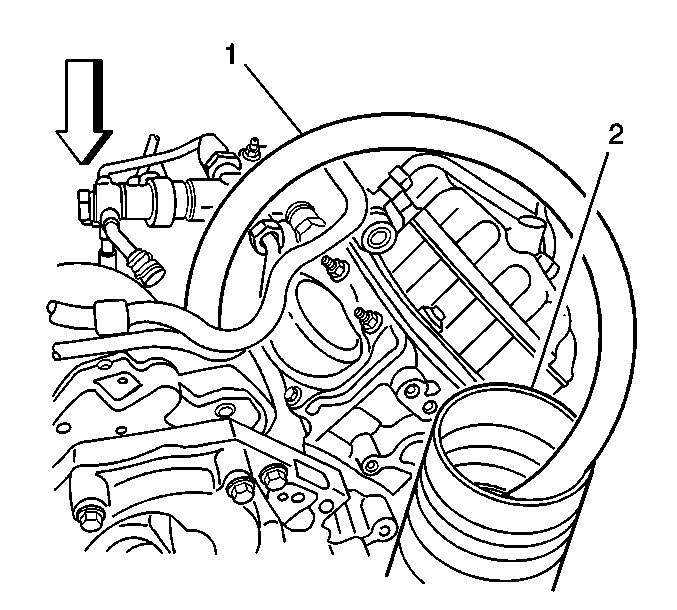
- Attach
a rubber hose (1) with a barbed fitting to the fuel injection pump return
hose and insert the other end into a 1 gallon clean fuel container (2).
- Remove the ignition 1 relay or EDU relay, as equipped,
using the J 43244
Relay Puller
Pliers.
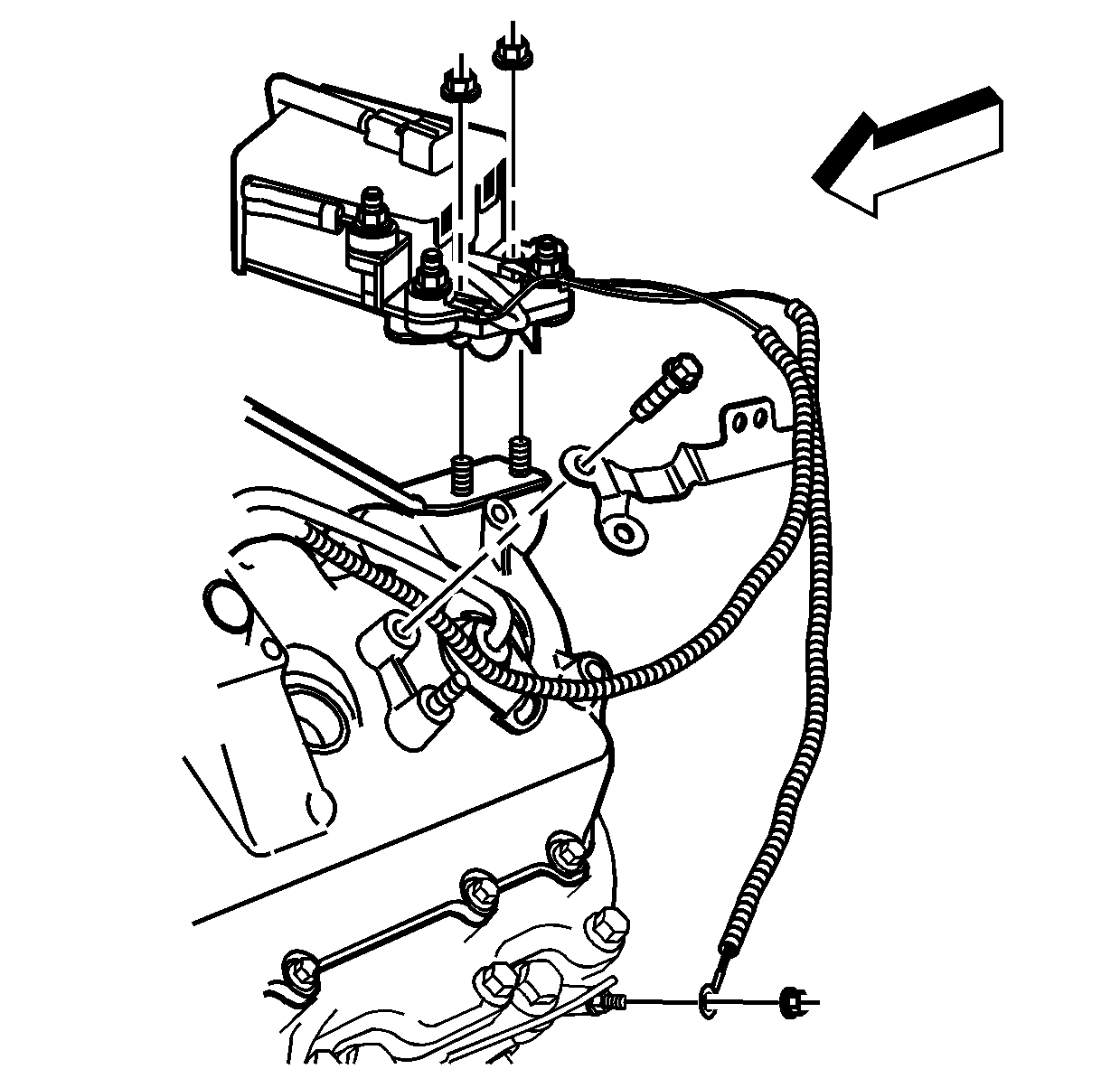
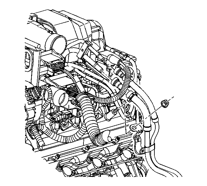
- Remove
the glow plug harness bracket bolt.
- Remove the glow plug harness bracket nut from the valve cover.
- Remove the glow plug controller/relay mounting nuts.
- Reposition the glow plug controller/relay.
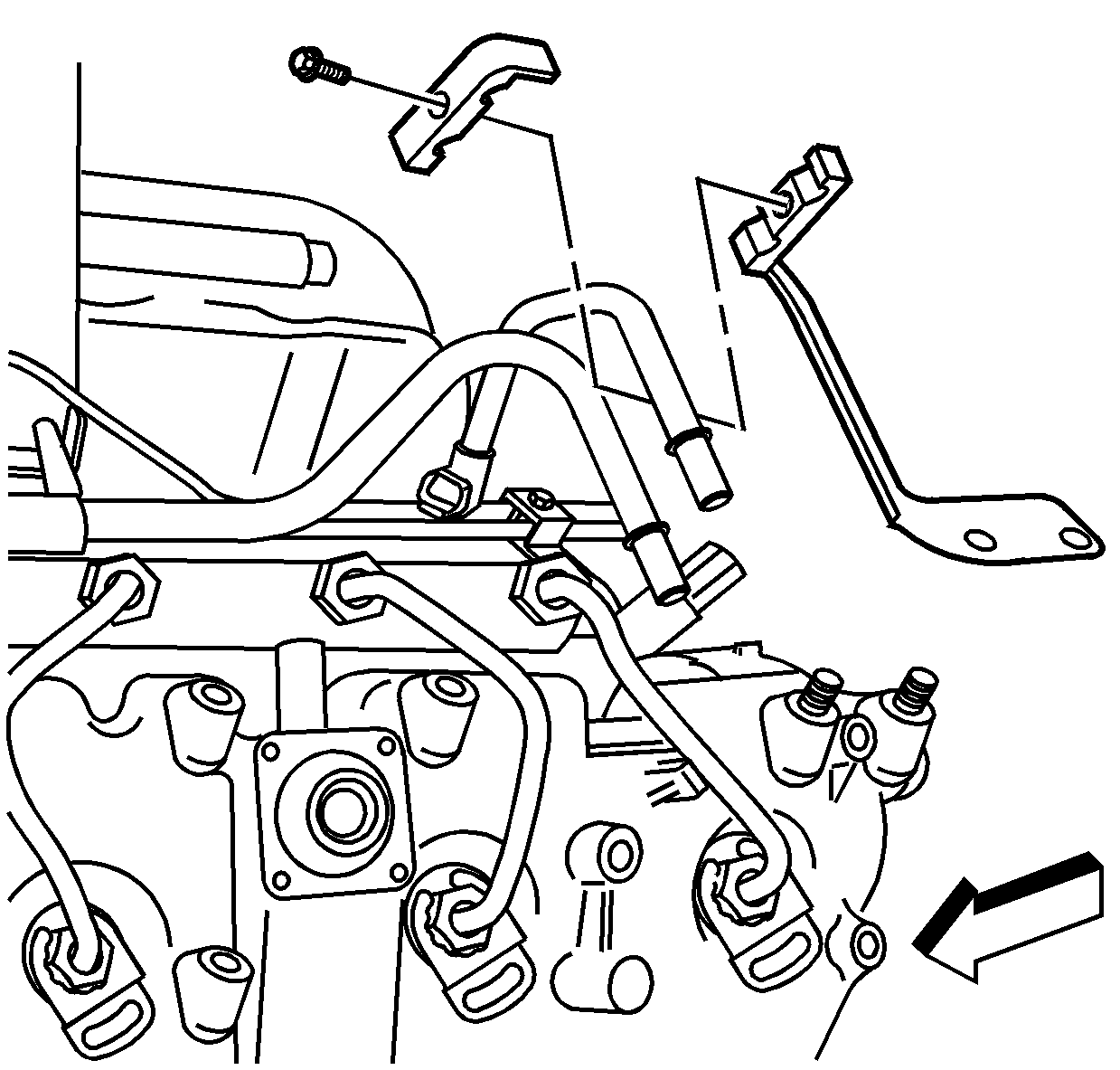
- Remove the fuel line retainers.
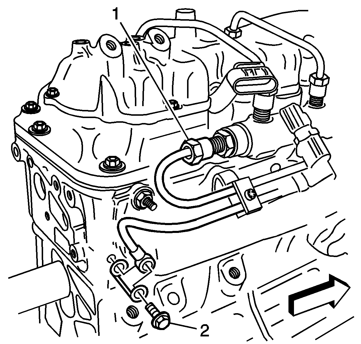
- Remove
the banjo bolt (2) from left rear cylinder head.
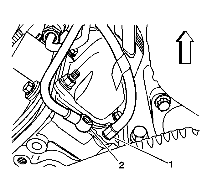
- Install the black hose (1) of the J 45873
to the left rear cylinder head
and install the other end of the hose into one of the J 45873
graduated cylinders.

- Remove
the banjo bolt (3) from the leak-off block.
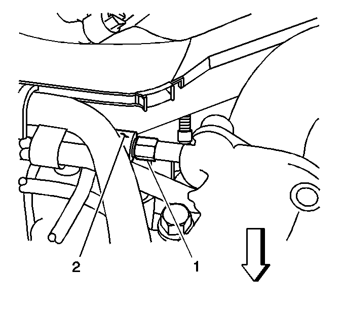
- Install the other black hose (1) of the J 45873
to the leak--off block
(2) and install the other end of the hose into another J 45873
graduated cylinders.

- Remove
the banjo bolt (4) from the junction block (2).
- Crank the engine for 15 seconds while observing the fuel pressure
relief valve on the junction block for fuel leakage.
| • | If no fuel is leaking from the fuel pressure relief valve, go to step 19. |
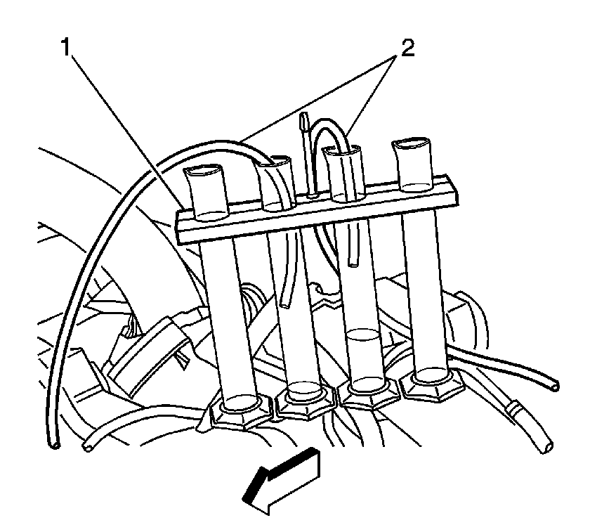
- Crank the engine in 15 second intervals,
with one minute cooling time between, until fuel starts to flow into one or both
of the J 45873
graduated cylinders (1).
- Elevate the hoses (2) to retain the fuel in the hoses, and empty the graduated
cylinders into a suitable container.
- Install the hoses (2) into 2 of the graduated cylinders (1).
Important: The engine cranking speed must be more than 150 RPM.
- Crank the engine for 15 seconds.
- Measure the quantity of fuel in each of the graduated cylinders. Refer
to
Fuel System Specifications
for fuel return
flow specifications.
| • | If there is less than the specified quantity from each cylinder bank,
replace the fuel injection pump and repeat steps 19-23. |
| • | If the fuel injection pump has already been replaced in this repair and
there is less than the specified quantity of fuel from each bank, go to step 45. |
Important: When the fuel injector pressure lines are removed, debris will fall into the
fuel injector inlet fitting. Vacuum the debris from the inlet fitting of the fuel
injector.
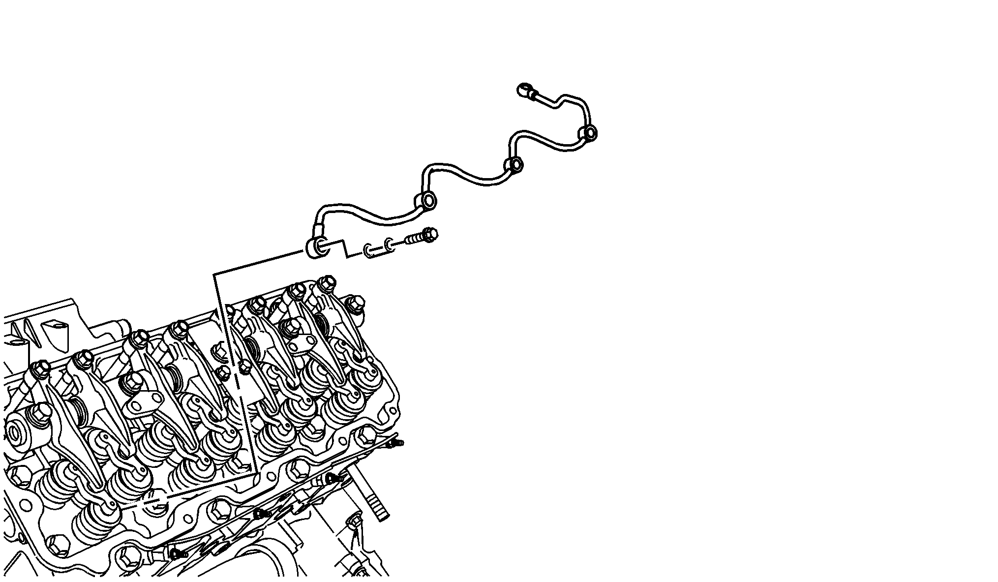
- Remove the return line from injectors.
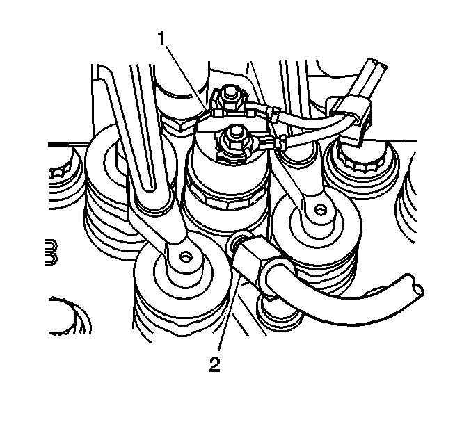
- Install the four yellow hoses (2)
from the J 45873
to the injectors (1)
and the other end of the hoses into each of the J 45873
graduated cylinders.
- Install the four injector supply lines.
Tighten
Tighten the supply lines to 44 N·m (32 lb ft).
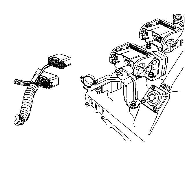
- Connect the engine-to-chassis harness connectors
to enable the starter.
- Install the fuel filter hoses, FICM hoses,
and the fuel supply hose. Push the fuel supply hose in until it locks.
- Install the black hoses from the J 45873
into the container that the fuel injection pump return hose is in.
Prime the fuel system 30 times to remove air from the fuel system. Air will
be forced out of the system within 2 minutes.
- Crank the engine in 15 second intervals, with one minute cooling
time between, until fuel starts to flow into one or more of the graduated cylinders.
- Elevate the four hoses to retain the fuel in the hoses, and empty the
4 graduated cylinders into a suitable container.
- Install the hoses in the graduated cylinders in numerical order.
Important: The engine cranking speed must be more than 150 RPM.
- Crank the engine for 15 seconds.
Important: A fuel injector may have high fuel return flow only at higher engine temperatures.
If the high return flow ceases between the bank return flow test and the individual
injector return flow test the fuel injectors may need to be heated to an operating
temperature before performing this test.
- Measure the quantity of fuel in each of the graduated cylinders. Refer to
Fuel System Specifications
for fuel return flow specifications.
Remove the fuel feed pipes from any injectors that have high return fuel flow, and
install the EN 47589
fuel pressure adapter
cap(s) to the fuel rail outlets. Then go to step 35.
- Repeat steps 30 through 34 until no fuel injectors have more than
the specified quantity of fuel flow.
- Were both banks of fuel injectors tested with steps 30 through
35?
| • | If the answer is YES, go to step 44. |
| • | If the answer is NO, go to step 37. |
- Ensure that the hoses are still installed as they were in steps 14
through 17.
- Prime the fuel system 30 times to remove the air from the fuel
system. Air will be forced out of the system within 2 minutes.

- Crank the engine in 15 second intervals,
with one minute cooling time between, until fuel starts to flow into one or both
of the J 45873
graduated cylinders (1).
- Elevate the hoses (2) to retain the fuel in the hoses, and empty the graduated
cylinders into a suitable container.
- Install the hoses (2) into 2 of the graduated cylinders (1).
Important: The engine cranking speed must be more than 150 RPM.
- Crank the engine for 15 seconds.
- Measure the quantity of fuel in each of the graduated cylinders. Refer
to
Fuel System Specifications
for fuel return
flow specifications.
If there is more than the specified quantity of fuel in either of the 2 cylinders,
remove the valve cover from that cylinder head. Refer to
Valve Rocker Arm Cover Replacement - Lower Left Side
or
Valve Rocker Arm Cover Replacement - Lower Right Side
. Then perform steps 29
through 35 on the bank of fuel injectors with the high fuel flow, Then go to step
44.
If both of the cylinder have less than the specified quantity of fuel, go to
step 44.
- Replace all of the fuel injectors that had fuel rail outlets capped. Refer
to
Fuel Injector Replacement
.
- Install all disconnected and removed components. Refer to the applicable
procedures.
- Start and idle the engine. You may have to prime the fuel system before
the engine will start.
- Connect a scan tool.
- Command the fuel pressure control to 160 MPa with a scan tool.
| • | If the fuel pressure is more than 145 MPa, the system is OK. |
Fuel Pressure Regulator Graphing
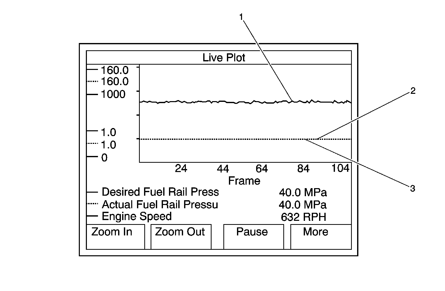
- Set up the scan tool in the following format:
| 1.1. | Select the Data Display on the scan tool. |
| 1.2. | Select Engine Data 1. |
| 1.3. | Select the More softkey 2 times. |
| 1.4. | Select the Live Plot softkey. |
| 1.5. | Select the Engine Speed, Actual Fuel Rail Pressure, and Desired Fuel Rail
Pressure parameters by highlighting each parameter and depressing the ENTER softkey. |
| 1.6. | Select the Accept softkey. |
| 1.7. | Select the More softkey, then select the Change Min/Max softkey. |
| 1.8. | Select the More softkey, and adjust the parameters to the following Min/Max
ranges: |
| • | The Engine Speed Min/Max range is 0 to 1000 RPM. |
| • | The Actual Fuel Rail Pressure Min/Max range is 1.0 to 160 MPa. |
| • | The Desired Fuel Rail Pressure Min/Max range is 1.0 to 160 MPa. |
- Start and idle the engine.
Good Fuel Pressure Regulator Graph, 0 Miles
