Transmission Replacement 4.8L, 5.3L, and 6.0L Engines
Tools Required
J 21366 Converter Holding Strap
Removal Procedure
- Disconnect the negative battery cable. Refer to Battery Negative Cable Disconnection and Connection l.
- Raise and suitably support the vehicle. Refer to Lifting and Jacking the Vehicle .
- Remove the rear propeller shaft. Refer to Two-Piece Propeller Shaft Replacement or One-Piece Propeller Shaft Replacement .
- Support the transmission with a transmission jack.
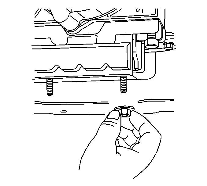
- Remove the nut securing the transmission mount to the transmission support.
- Remove the nuts and bolts securing the transmission support to the frame.
- Raise the transmission slightly and remove the transmission support from the vehicle.
- Remove the exhaust pipe. Refer to Exhaust Manifold Pipe Replacement .
- Remove the catalytic converter. Refer to Catalytic Converter Replacement .
- Remove the starter motor. Refer to Starter Motor Replacement .
- If the vehicle is equipped with a transfer case, remove the front propeller shaft. Refer to Front Propeller Shaft Replacement .
- Lower the transmission to gain access to the top and sides of the transmission.
- Disconnect the vent tube hose and the electrical connections from the transfer case, if equipped.
- Remove the transmission mount.
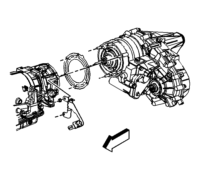
- Remove the transfer case, if equipped. Refer to the appropriate procedure:
- Remove the shift cable end from the transmission shift lever ball stud and the pan rail bracket. Refer to Range Selector Lever Cable Replacement .
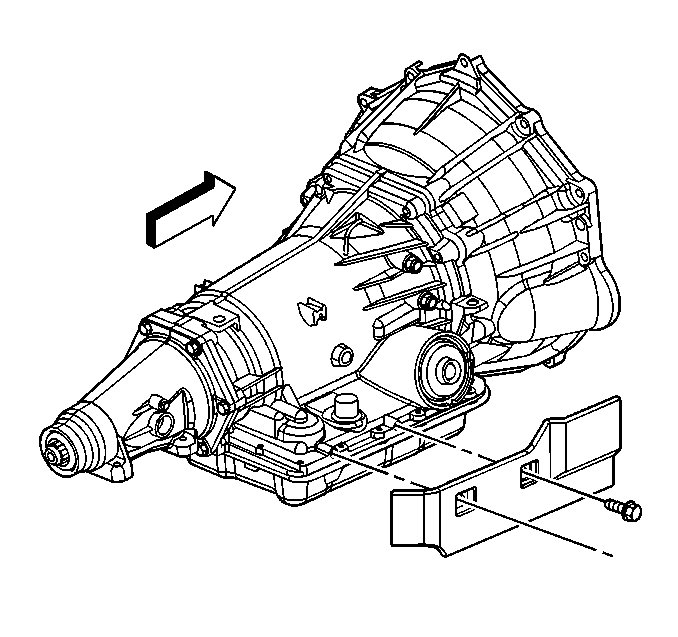
- Remove the transmission heat shield.
- Disconnect the transmission vent hose, the park/neutral position switch connector, and the main electrical connector from the transmission. Refer to Park/Neutral Position Switch Replacement .
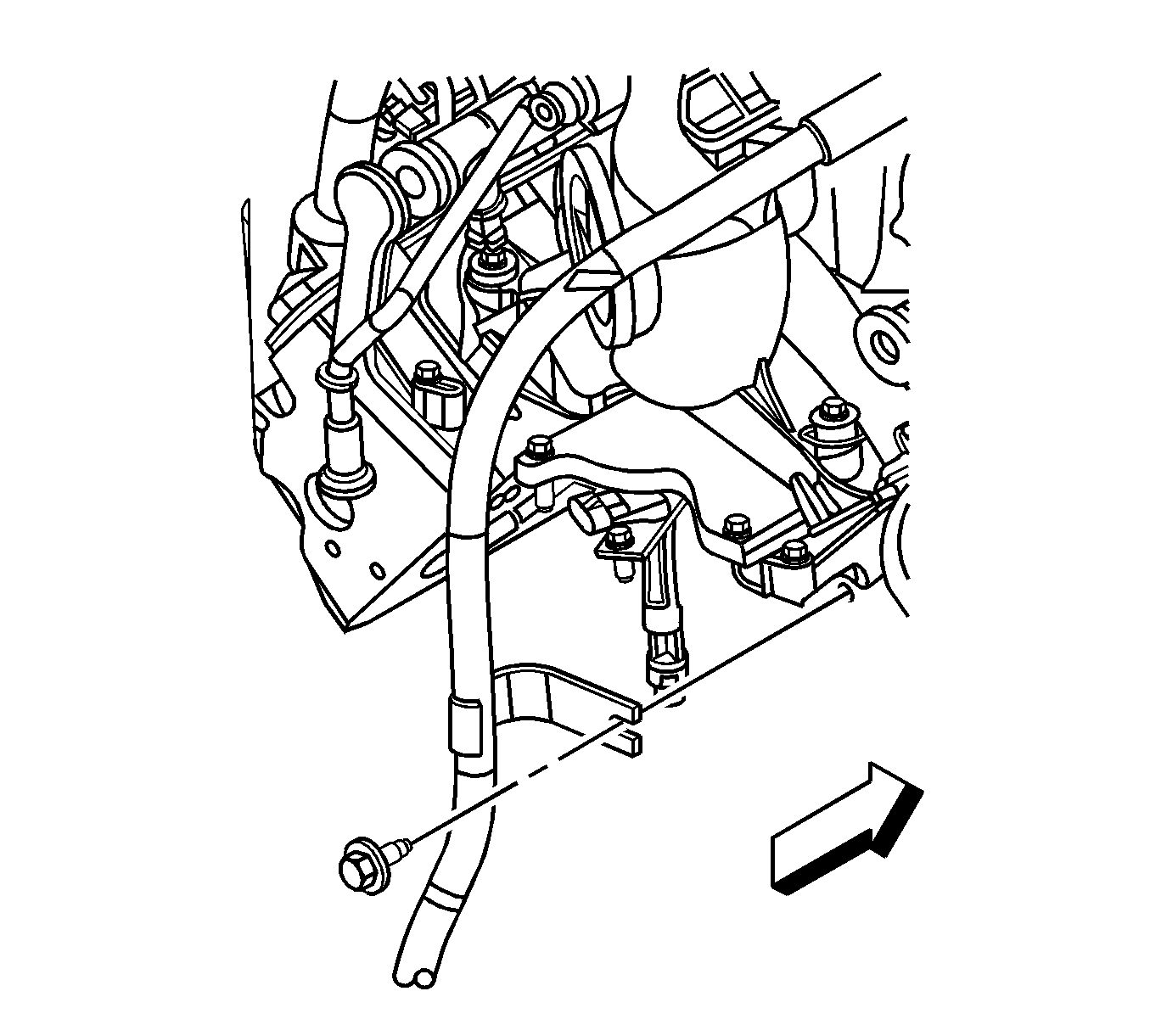
- Remove the bolt that secures the fuel line bracket to the left side of the transmission.
- Remove the torque converter access plug.
- Remove the flywheel to torque converter bolts.
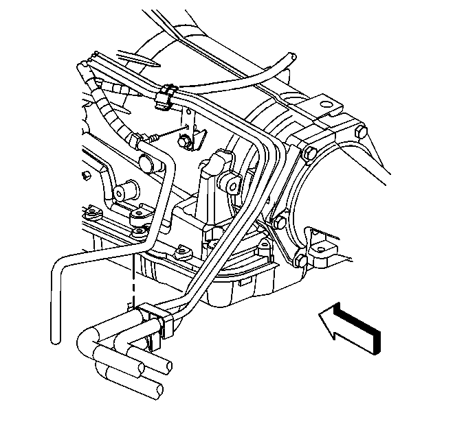
- Disconnect the transmission oil cooler lines from the transmission. Refer to Transmission Fluid Cooler Hose/Pipe Quick-Connect Fitting Disconnection and Connection .
- Plug the transmission oil cooler line connectors in the transmission case.
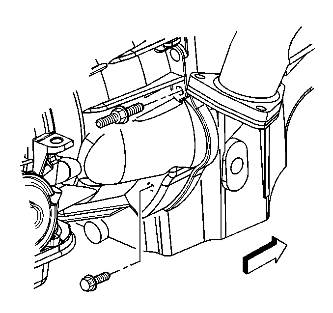
- Remove the stud and the bolt securing the transmission to the engine.
- Remove the six studs and one bolt securing the transmission to the engine.
- Install the J 21366 onto the transmission bell housing to retain the torque converter.
- Pull the transmission straight back.
- Remove the transmission from the vehicle while simultaneously removing the fluid level indicator tube.
- Flush the transmission oil cooler and cooling lines if necessary. Refer to Transmission Fluid Cooler Flushing and Flow Test .
Caution: Refer to Battery Disconnect Caution in the Preface section.
| • | Transfer Case Assembly Replacement for the NVG 261-NP2 transfer case |
| • | Transfer Case Assembly Replacement for the NVG 149-NP transfer case |
| • | Transfer Case Assembly Replacement for the NVG 263-NP1 transfer case |
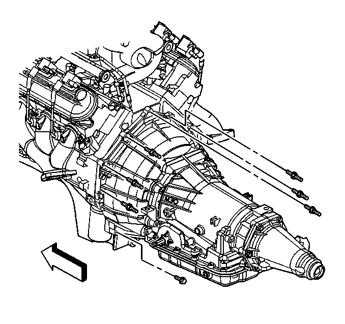
Installation Procedure
- Install the J 21366 onto the transmission bell housing to retain the torque converter.
- Support the transmission with a transmission jack.
- Raise the transmission into place while simultaneously installing the fluid indicator tube.
- Remove the J 21366 from the transmission.
- Slide the transmission straight onto the locating pins while lining up the marks on the flywheel and the torque converter.
- Install six studs and one bolt securing the transmission to the engine.
- Install the stud and bolt securing the transmission to the engine.
- If reusing the torque converter bolts, clean the bolt threads and apply LOCTITE 242, GM P/N 12345382 (Canadian P/N 10953489), or equivalent to the threads prior to installation.
- Install the flywheel to torque converter bolts.
- Install the torque converter access plug.
- Install the transmission vent hose, fuel lines, and the wiring harness to the transmission.
- Install the two bolts securing the heat shield to the transmission.
- Install the shift cable to the shift lever ball stud and the bracket. Refer to Range Selector Lever Cable Replacement
- Install the transfer case, if equipped. Refer to the appropriate procedure:
- Install the two bolts and nut securing the transmission rear mount to the transmission.
- Connect the vent hose and electrical connectors to the transfer case, if equipped.
- If the vehicle is equipped with a transfer case, install the front propeller shaft. Refer to Front Propeller Shaft Replacement .
- Install the starter motor. Refer to Starter Motor Replacement .
- Install the catalytic converter. Refer to Catalytic Converter Replacement .
- Install the exhaust pipe assembly. Refer to Exhaust Manifold Pipe Replacement .
- Install the transmission support to the vehicle.
- Install the transmission mount to transmission support nut.
- Remove the transmission jack.
- Install the rear propeller shaft. Refer to Two-Piece Propeller Shaft Replacement or One-Piece Propeller Shaft Replacement .
- Connect the oil cooler lines to the transmission. Refer to Transmission Fluid Cooler Hose/Pipe Replacement .
- Lower the vehicle.
- Connect the negative battery cable. Refer to Battery Negative Cable Disconnection and Connection .
- Fill the transmission to the proper level. Refer to Transmission Fluid Check .
- Reset the TAP values. Refer to Transmission Adaptive Functions .
The torque converter must rotate freely by hand.
Notice: Refer to Fastener Notice in the Preface section.

Tighten
Tighten the studs and the bolt to 50 N·m (37 lb ft).

Tighten
Tighten the stud and the bolt to 50 N·m (37 lb ft).
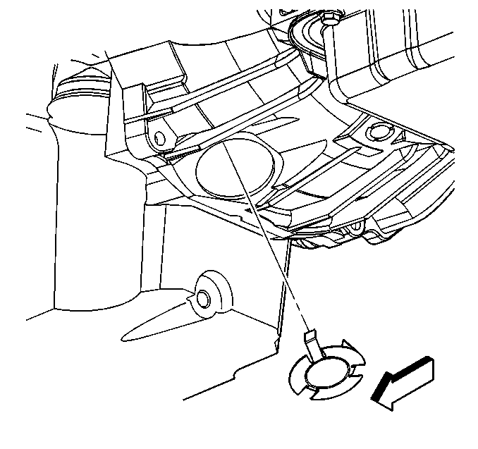
Tighten
Tighten the bolts to 63 N·m (46 lb ft).


Tighten
Tighten the bolt to 17 N·m (13 lb ft).
| • | Transfer Case Assembly Replacement for the NVG 261-NP2 transfer case |
| • | Transfer Case Assembly Replacement for the NVG 149-NP transfer case |
| • | Transfer Case Assembly Replacement for the NVG 263-NP1 transfer case |

Tighten
Tighten the bolts and nut to 25 N·m (18 lb ft).
Tighten
Tighten the bolts to 70 N·m (50 lb ft).
Tighten
Tighten the nuts to 40 N·m (29 lb ft).
Caution: Refer to Battery Disconnect Caution in the Preface section.
Important: It is recommended that transmission adaptive pressure (TAP) information be reset.
Resetting the TAP values using a scan tool will erase all learned values in all cells. As a result, The engine control module (ECM), powertrain control module (PCM) or transmission control module (TCM) will need to relearn TAP values. Transmission performance may be affected as new TAP values are learned.Transmission Replacement 5.3L Engine w/RPO HP2
Tools Required
J 21366 Converter Holding Strap
Caution: To help avoid personal injury, always treat the 3-phase cable and connectors as if voltage is present and as if the surface of all parts of the cable is hot.
Caution: To help avoid personal injury, always disconnect the 36V generator battery carrier before doing any work to the generator battery carrier system. To disconnect the generator battery carrier, turn the engine off and turn OFF the service disconnect switch, which is located on the passenger side of the generator battery carrier.
Removal Procedure
- Disconnect the energy storage box (ESB). Refer to Hybrid Battery Service Disconnect/Connect in Engine Electrical.
- Disconnect the negative battery cable. Refer to Battery Negative Cable Disconnection and Connection in Engine Electrical.
- Remove the intake manifold. Refer to Intake Manifold Replacement .
- Remove the 3-phase cable bracket cover bolt (1).
- Remove the starter/generator control module (SGCM) cover bolts and cover.
- Remove the 3-phase cable nuts.
- Remove the 3-phase cable from the SGCM studs.
- From under the hood, remove the transmission fill tube bolt. Reposition the fill tube.
- Drain the cooling system and engine block. Refer to Cooling System Draining and Filling in Engine Cooling.
- Raise and suitably support the vehicle. Refer to Lifting and Jacking the Vehicle in General Information.
- Drain the transmission fluid.
- Remove the transfer case, if equipped. Refer to Transfer Case Assembly Replacement in Transfer Case - NVG 261-NP2, or Transfer Case Assembly Replacement in Transfer Case - NVG 246-NP8.
- Remove the rear propeller shaft, if vehicle is a 2-wheel drive (2WD). Refer to One-Piece Propeller Shaft Replacement in Propeller Shaft.
- If vehicle is a 2WD, support the engine with a suitable adjustable jack.
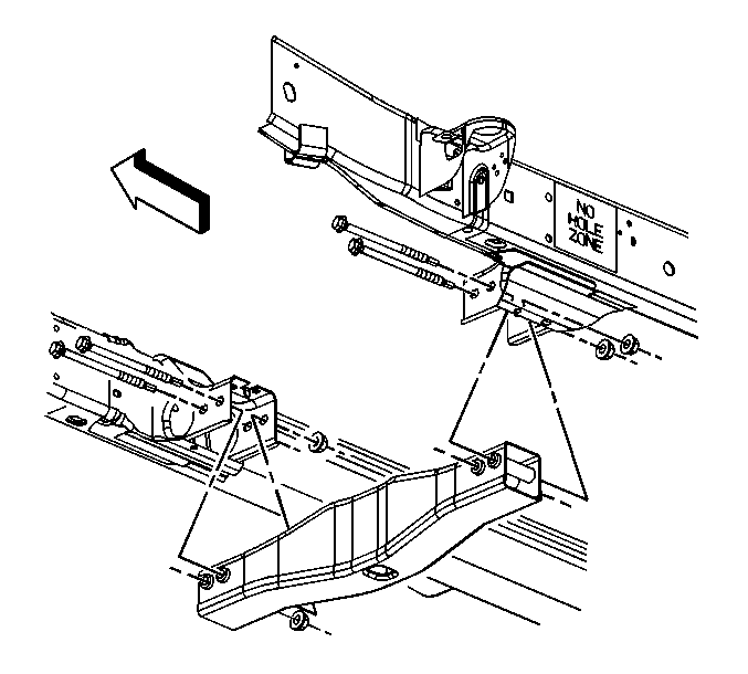
- If vehicle is a 2WD, remove the crossbar bolts and bar.
- Support the transmission with a transmission jack.
- Remove the transmission mount nuts.
- Remove the transmission support bolts and nuts.
- Raise the transmission slightly and remove the transmission support.
- Remove the catalytic converter. Refer to Catalytic Converter Replacement in Engine Exhaust.
- Lower the transmission slightly, in order to gain access to the top of the transmission.
- Remove the transmission heat shield bolts and shield.
- Remove the connector position assurance (CPA) retainer.
- Disconnect the park/neutral position (PNP) switch electrical connector (2).
- Disconnect the transmission harness 20-way connector (1) from the internal harness pass-through connector.
- If vehicle is a 2WD, disconnect the vehicle speed sensor (VSS) (2).
- Remove the bolt that secures the fuel line bracket to the left side of the transmission.
- Reposition the harness out of the way.
- Disconnect the range selector cable end (2) from the transmission range selector lever ball stud (1).
- Remove the transmission range selector cable bracket bolts (1).
- Reposition the selector cable bracket (2) and cable out of the way.
- Remove the driver side exhaust heat shield nuts (2).
- Remove the driver side exhaust heat shield (1).
- Remove the thermal bypass hose bolt.
- Reposition the thermal bypass hose clamp.
- Remove the thermal bypass hose from the fitting.
- Remove the coolant inlet pipe to stator bolt (4).
- Reposition the inlet pipe (3) out of the way.
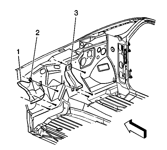
- Remove the driver side closeout cover bolt and cover.
- Remove the passenger side closeout cover bolt and cover.
- Remove the engine shield bolts and shield, if necessary.
- Remove the torque converter bolts.
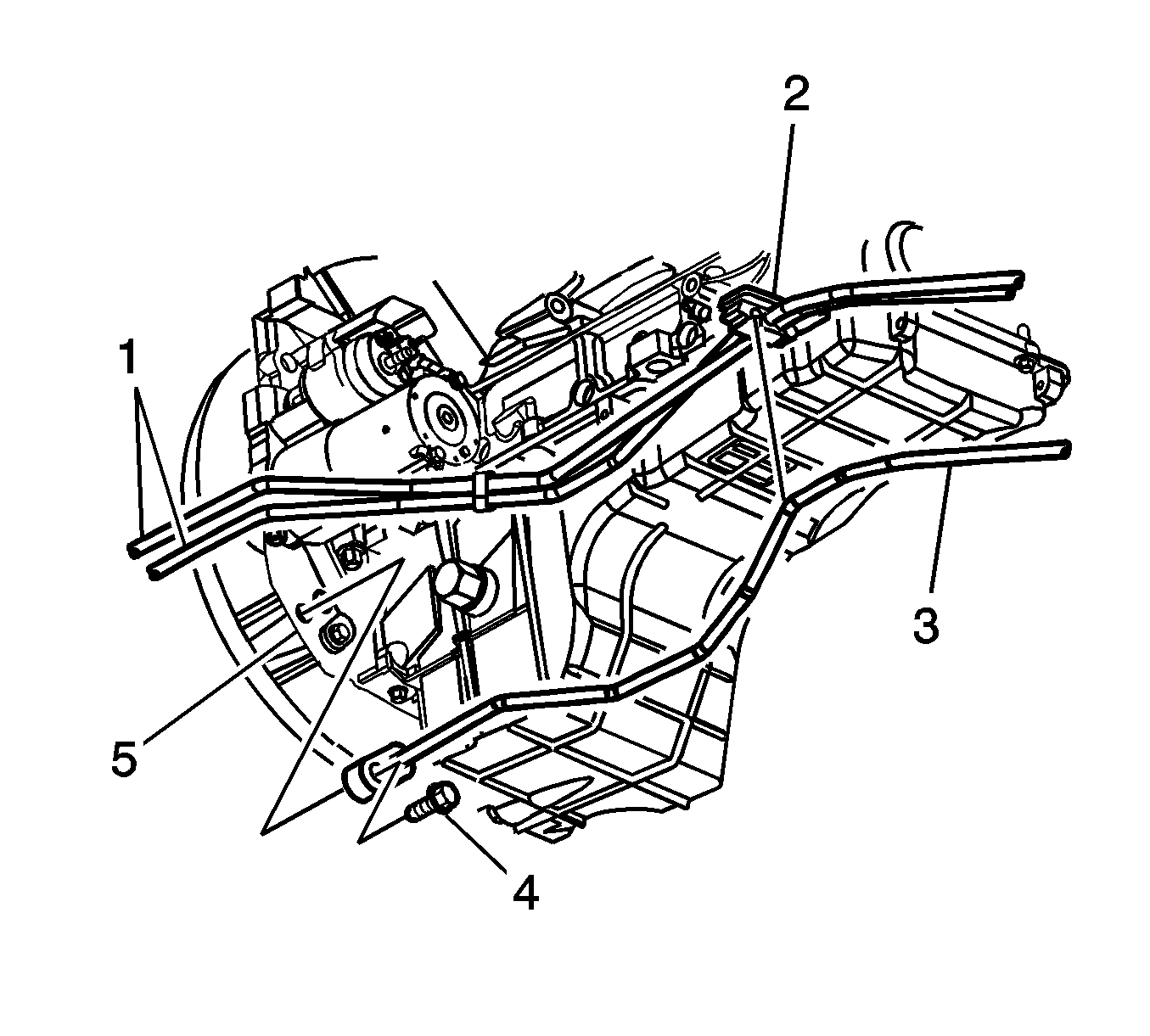
- Disconnect the transmission oil cooler lines from the transmission. Refer to Transmission Fluid Cooler Hose/Pipe Quick-Connect Fitting Disconnection and Connection .
- Plug the transmission oil cooler lines and fittings.
- Lower the transmission, in order to access the 3-phase cable cover.
- Remove the 3-phase cable cover nuts (3).
- Remove the 3-phase cable nuts (4).
- Remove the 3-phase cable from the stator studs.
- Position the 3-phase cable up and out of the way, in order to access the fill tube bolt.
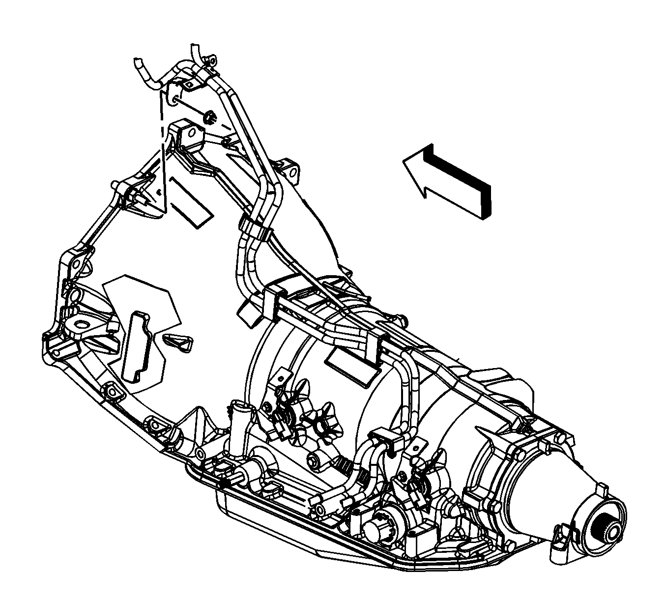
- Remove the fuel line bracket nut and bracket from the upper left bellhousing stud.
- Remove the transmission vent hose bracket nut and bracket from the top bellhousing stud.
- Remove the vent hose from the transmission.
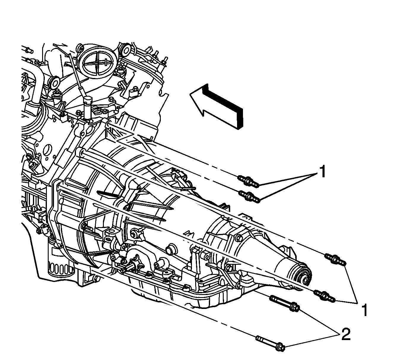
- Remove the transmission studs (1) and bolts (2) to the engine.
- Remove the transmission nuts to the engine.
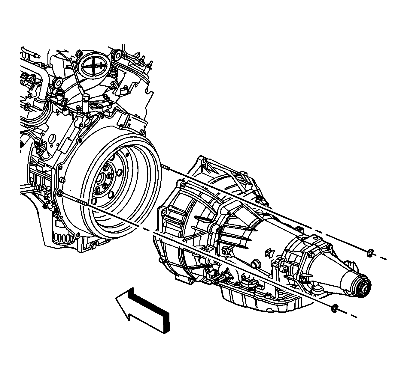
- Pull the transmission straight back in order to disengage the torque converter.
- Once the transmission is pulled back far enough, install J 21366 onto the bell housing in order to retain the torque converter.
- Once the transmission is far enough back, remove the driver side stator stud.
- Remove the transmission from the vehicle while simultaneously removing the fluid level indicator tube.
- Flush the transmission oil cooler and cooling lines if necessary. Refer to Transmission Fluid Cooler Flushing and Flow Test .
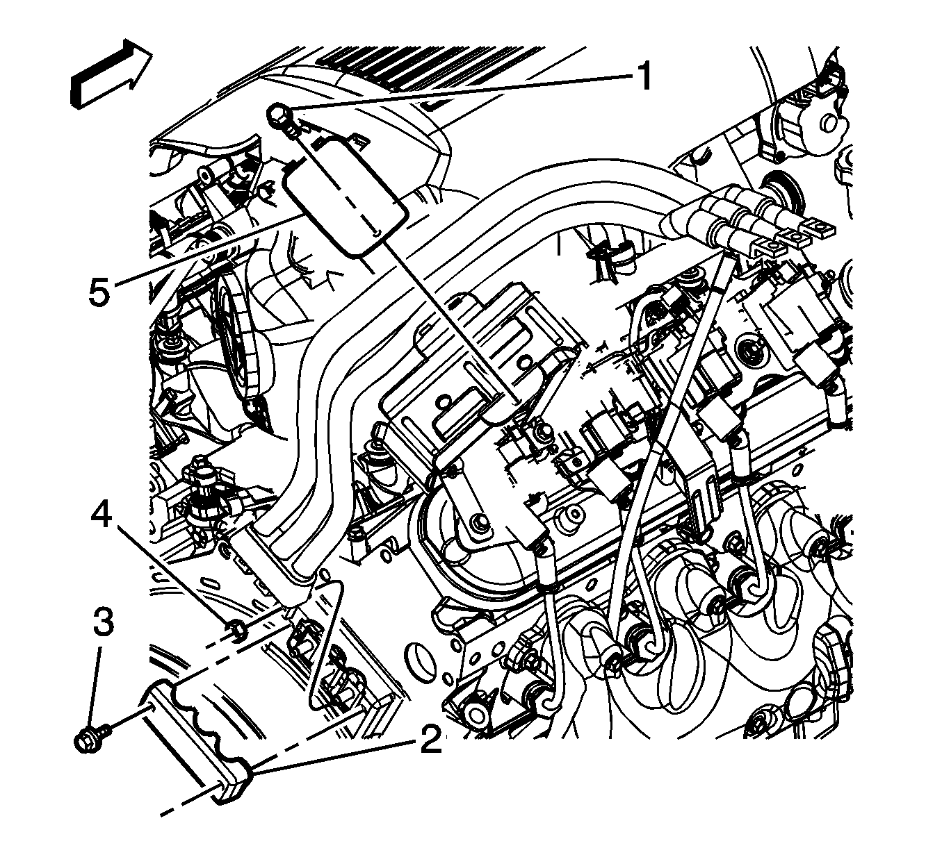
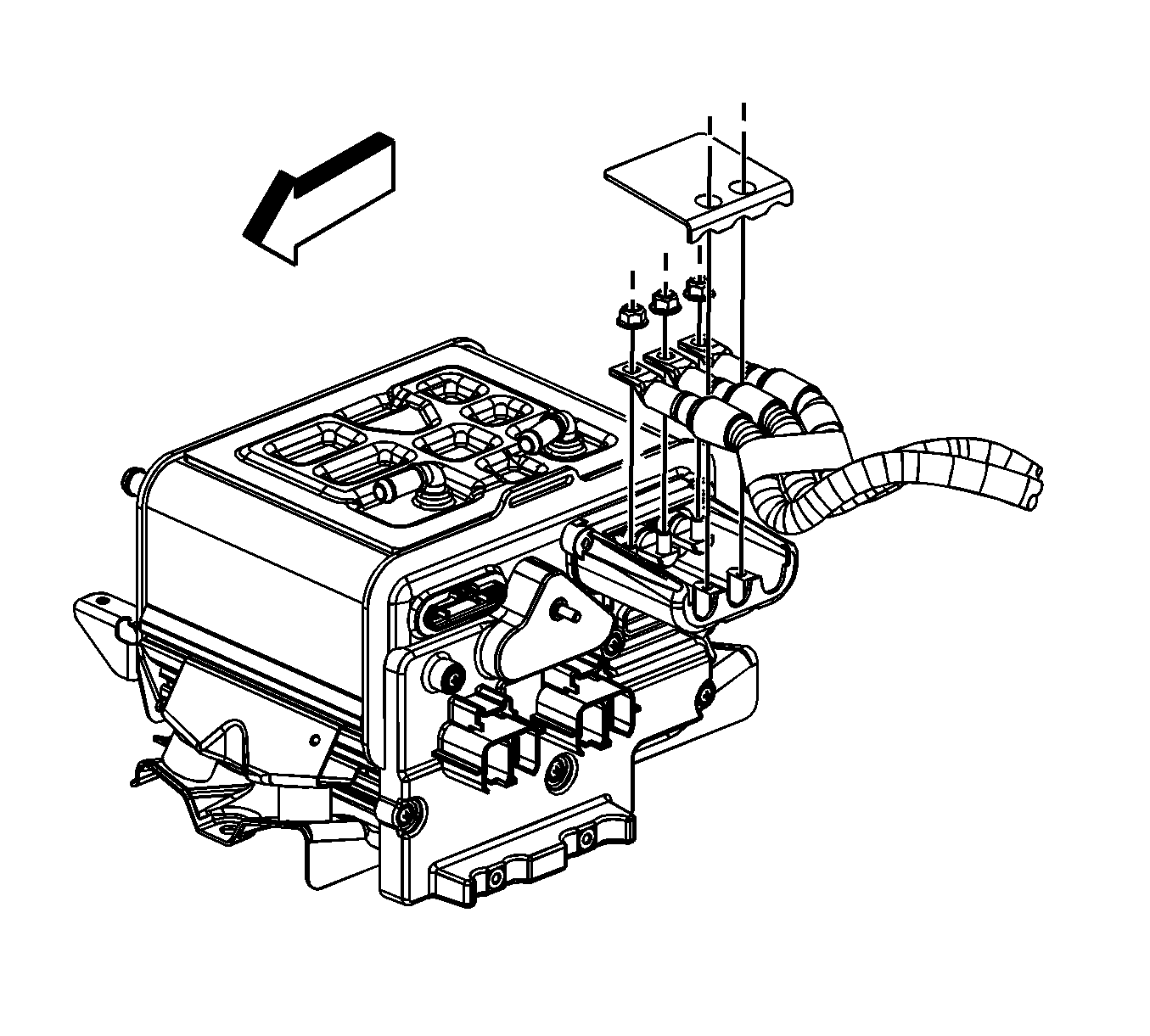
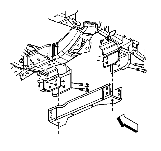
Important: If the vehicle is a 2WD, it is necessary to remove the crossbar, in order to remove the transmission.


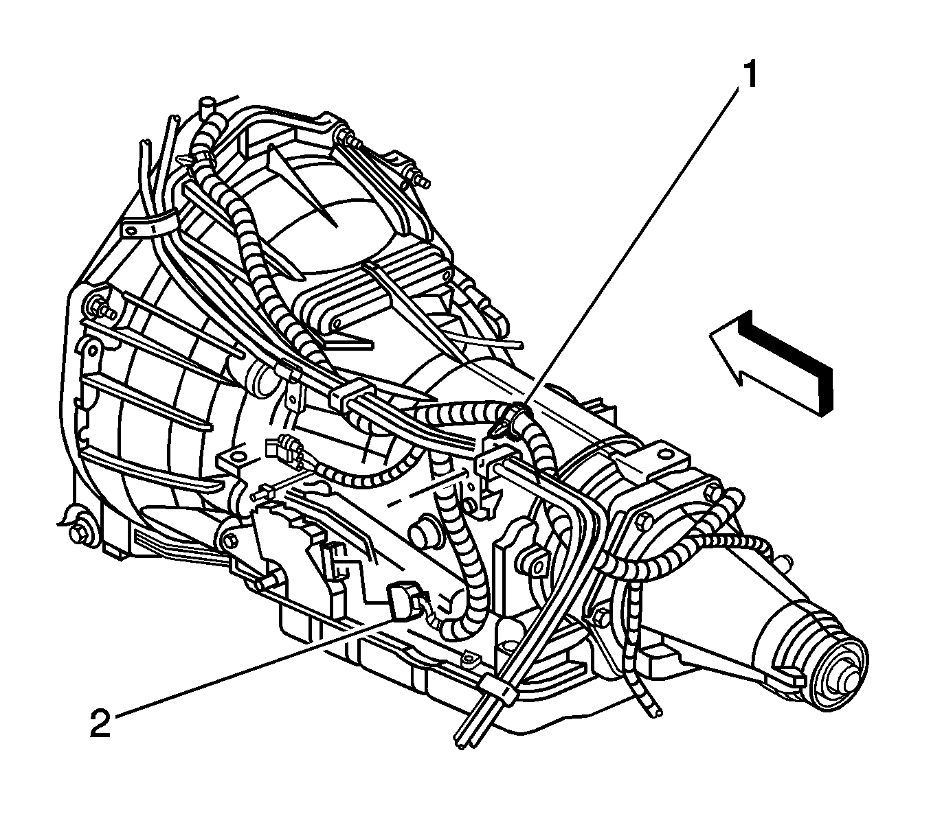
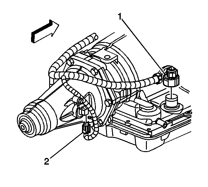
Depress both tabs on the connector and pull straight up; do not pry the connector.

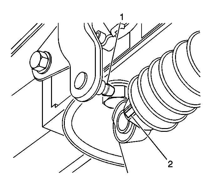
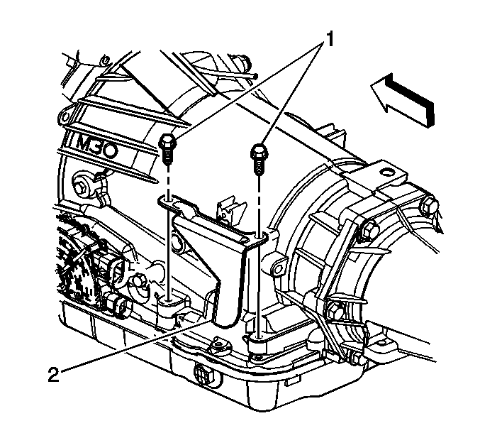
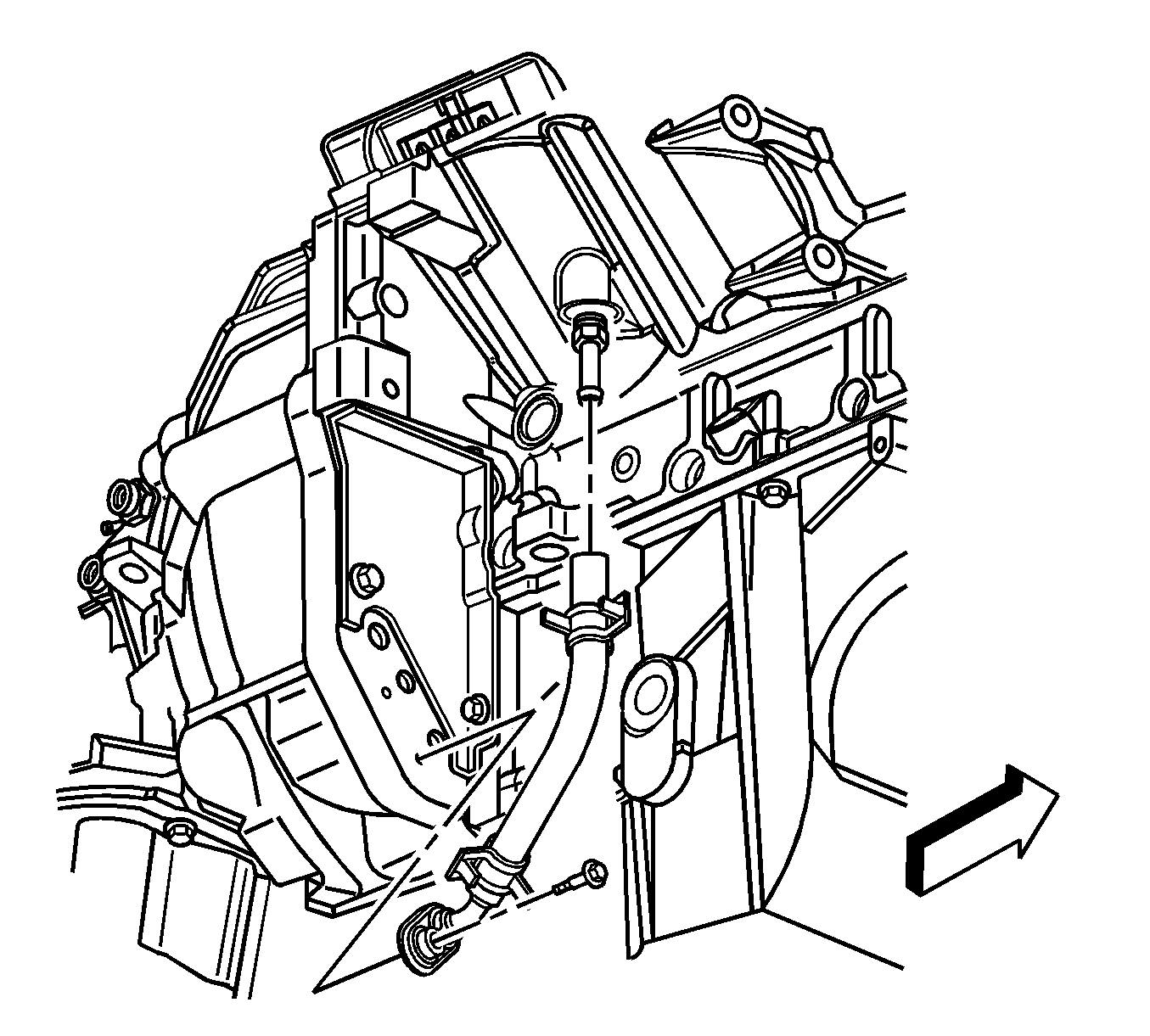
Important: Ensure that the O-ring seal is removed with the hose.
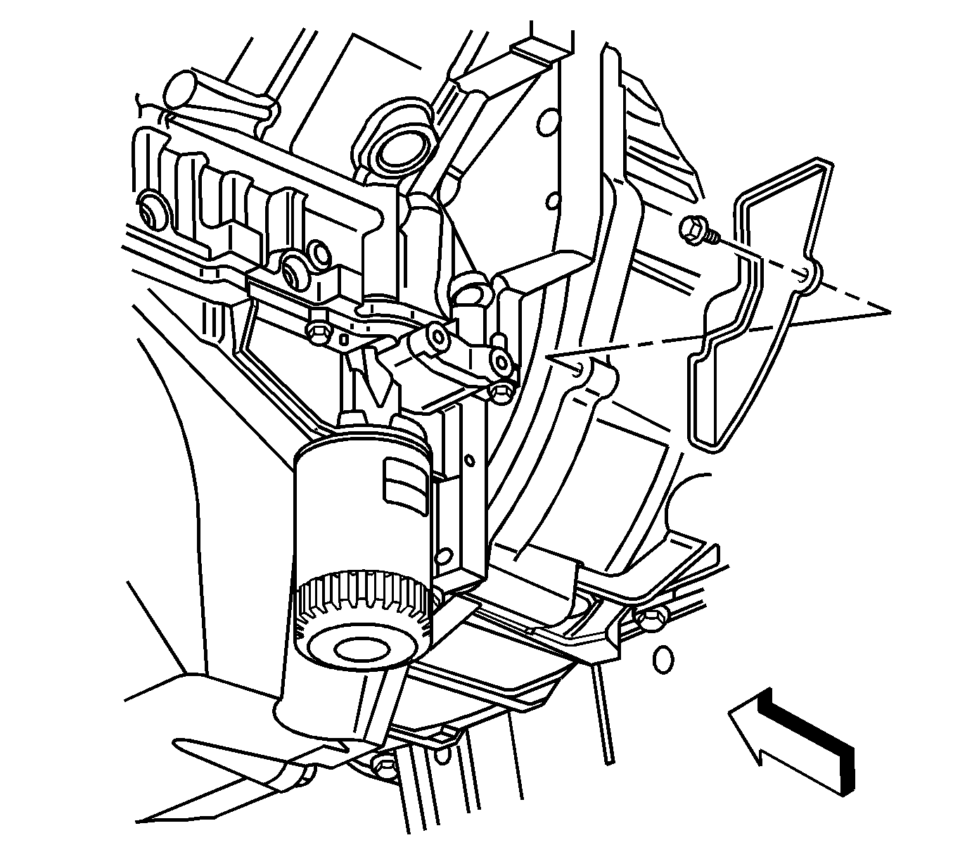
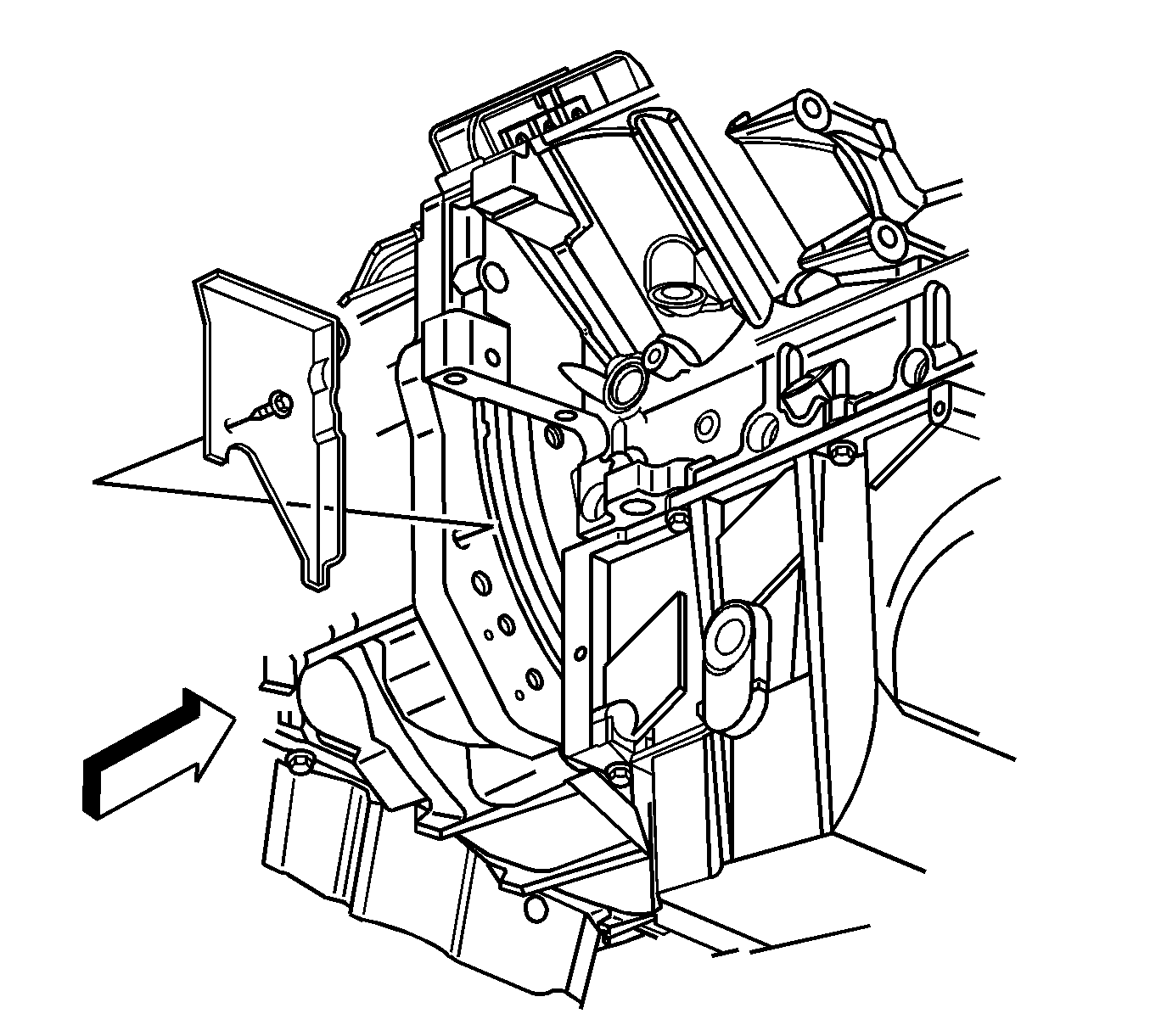
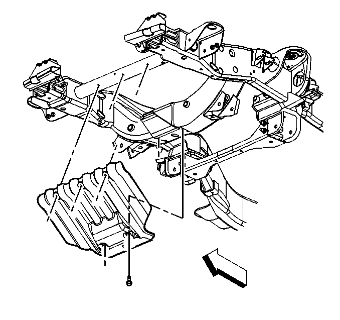
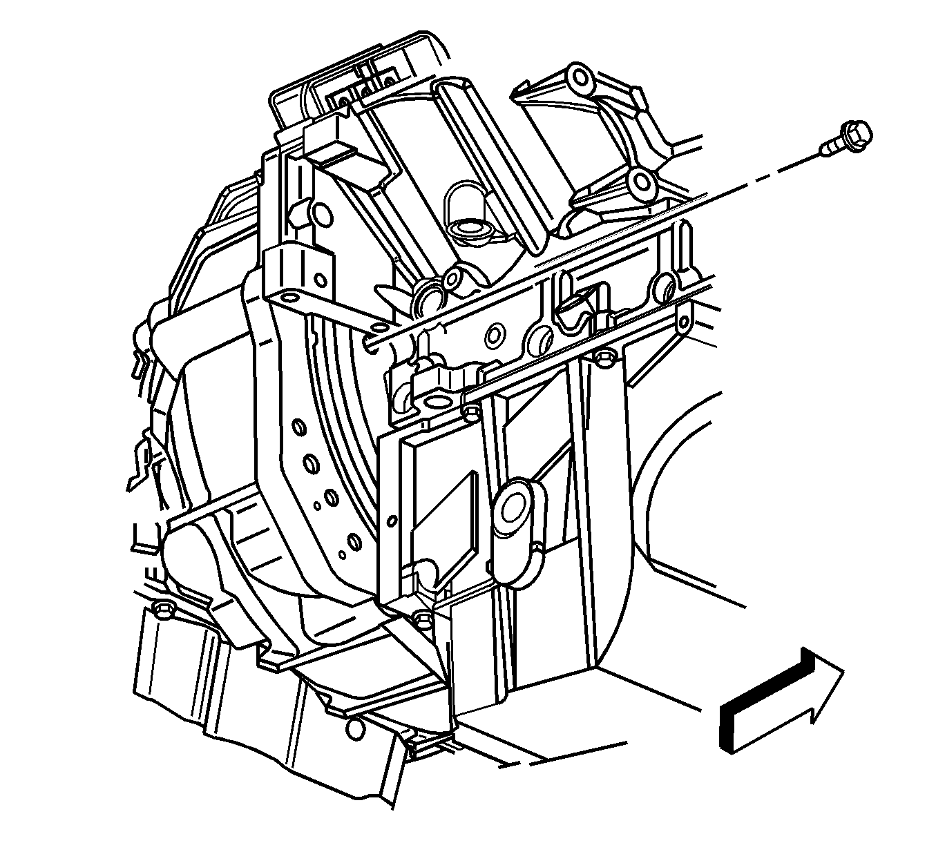
Important: It is highly recommended to use a 3/8 inch, 6 point shallow thin wall socket and a wobble extension to loosen the torque converter bolts and a 8 mm ball end hex key to remove the bolts in order to prevent possibly stripping the bolts.
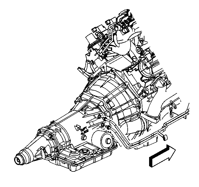

Installation Procedure
- Install the transmission to the vehicle while simultaneously installing the fluid level indicator tube.
- Once the transmission is half way installed, install the driver side stator stud.
- Once the transmission is half way installed, remove J 21366 from the bellhousing.
- Slide the transmission forward in order to engage the torque converter.
- Install the transmission nuts to the engine.
- Install the transmission studs (1) and bolts (2) to the engine.
- Install the vent hose to the transmission.
- Install the transmission vent hose bracket and nut to the top bellhousing stud.
- Install the fuel line bracket and nut to the upper left bellhousing stud.
- Position the 3-phase cable to the stator studs.
- Install the 3-phase cable nuts (4).
- Tighten the nuts a first pass to 14 N·m (10 lb ft).
- Tighten the nuts a final pass to 14 N·m (10 lb ft).
- Install the 3-phase cable cover and nuts (3).
- Raise the transmission to a level position.
- Remove the torque converter access plug.
- Rotate the torque converter in order to align the converter bolt holes with the flexplate holes.
- Install the torque converter bolts.
- Install the torque converter access plug.
- Install the engine shield and bolts, if necessary.
- Install the passenger side closeout cover and bolt.
- Install the driver side closeout cover and bolt.
- Position the inlet pipe (3) to the stator.
- Install the coolant inlet pipe to stator bolt (4).
- Install the thermal bypass hose to the fitting.
- Position the thermal bypass hose clamp.
- Install the thermal bypass hose bolt.
- Install the driver side exhaust heat shield (1).
- Install the driver side exhaust heat shield nuts (2).
- Position the selector cable bracket (2) and cable.
- Install the transmission range selector cable bracket bolts (1).
- Connect the range selector cable end (2) to the transmission range selector lever ball stud (1).
- Position the harness to the transmission.
- Install the bolt that secures the fuel line bracket to the left side of the transmission.
- If vehicle is a 2WD, connect the VSS (2).
- Connect the transmission harness 20-way connector (1) to the internal harness pass-through connector.
- Connect the PNP switch electrical connector (2).
- Install the CPA retainer.
- Install the transmission heat shield and bolts.
- Raise the transmission slightly.
- Install the catalytic converter. Refer to Catalytic Converter Replacement in Engine Exhaust.
- Install the transmission support.
- Install the transmission support bolts and nuts.
- Lower the transmission onto the support.
- Install the transmission mount nuts.
- Remove the support from the transmission.
- If vehicle is a 2WD, remove the support from the engine.
- If vehicle is a 2WD, install the crossbar bolts and bar.
- If vehicle is a 2WD, install the rear propeller shaft. Refer to One-Piece Propeller Shaft Replacement in Propeller Shaft.
- Remove the plugs from the transmission oil cooler lines and fittings.
- Connect the transmission oil cooler lines to the transmission. Refer to Transmission Fluid Cooler Hose/Pipe Quick-Connect Fitting Disconnection and Connection
- Install the transfer case, if equipped. Refer to Transfer Case Assembly Replacement in Transfer Case - NVG 261-NP2, or Transfer Case Assembly Replacement in Transfer Case - NVG 246-NP8.
- From under the hood, Position the fill tube. install the fill tube bolt.
- Install the 3-phase cable to the SGCM studs.
- Install the 3-phase cable nuts.
- Install the SGCM cover and bolts.
- Install the 3-phase cable bracket cover bolt (1).
- Install the intake manifold. Refer to Intake Manifold Replacement .
- Connect the negative battery cable. Refer to Battery Negative Cable Disconnection and Connection in Engine Electrical.
- Refill the cooling system and engine block. Refer to Cooling System Draining and Filling in Engine Cooling.
- Connect the ESB. Refer to Hybrid Battery Service Disconnect/Connect in Engine Electrical.
- Fill the transmission to the correct capacity. Refer to Approximate Fluid Capacities in Maintenance and Lubrication.
- Reset the TAP values. Refer to Transmission Adaptive Functions .

Notice: Refer to Fastener Notice in the Preface section.
Tighten
Tighten the stud to 16 N·m (12 lb ft).
Tighten
Tighten the nuts to 12 N·m (106 lb in).

Tighten
Tighten the bolts and studs to 50 N·m (37 lb ft).

Tighten
Tighten the nut to 12 N·m (106 lb in).
Tighten
Tighten the nut to 12 N·m (106 lb in).

Tighten
Important: The 3-phase cable cover studs may have a tendency to spread apart when the nuts are torqued. Once they have spread apart, they may not align with the holes in the cover. The studs can be realigned by squeezing them together at the tips. Each stud has a hex on the tip end where a tool cane be place without damaging the threads.
Tighten
Tighten the nuts to 9 N·m (80 lb in).


Important: It is highly recommended to use a 8 mm ball end hex key to install and hand tighten the torque converter bolts, then a 3/8 inch, 6 point shallow thin wall socket and a wobble extension to torque the torque converter bolts in order to prevent possibly stripping the bolts.
Tighten
Tighten the bolts to 63 N·m (46 lb ft).


Tighten
Tighten the bolt to 20 N·m (15 lb ft).

Tighten
Tighten the bolt to 12 N·m (106 lb in).

Tighten
Tighten the bolt to 12 N·m (106 lb in).

Tighten
Tighten the bolt to 9 N·m (80 lb in).

Important: Ensure that there is a O-ring seal on the bypass hose end that attaches to the transmission.
Tighten
Tighten the bolt to 10 N·m (89 lb in).

Tighten
Tighten the nuts to 9 N·m (80 lb in).

Tighten
Tighten the bolts to 25 N·m (18 lb ft).


Tighten
Tighten the bolt to 10 N·m (89 lb in).


Tighten
Tighten the bolts to 17 N·m (13 lb ft).

Tighten
Tighten the bolts to 70 N·m (50 lb ft).

Tighten
Tighten the nuts to 40 N·m (29 lb ft).

Tighten
Tighten the bolts to 100 N·m (74 lb ft).


Tighten
Tighten the bolt to 18 N·m (13 lb ft).

Tighten
Tighten the nuts to 15 N·m (11 lb ft).
Tighten
Tighten the bolts to 9 N·m (80 lb in).

Tighten
Tighten the bolt to 9 N·m (80 lb in).
Important: It is recommended that transmission adaptive pressure (TAP) information be reset.
Resetting the TAP values using a scan tool will erase all learned values in all cells. As a result, The ECM, PCM or TCM will need to relearn TAP values. Transmission performance may be affected as new TAP values are learned.